Handbook of Plastics Technologies Part 12 pps
Bạn đang xem bản rút gọn của tài liệu. Xem và tải ngay bản đầy đủ của tài liệu tại đây (566.06 KB, 40 trang )
PLASTICS JOINING 7.35
3. Plasma treatment (exposing the surface to ionized inert gas)
4. Metal-ion treatment (e.g., sodium naphthalene process for fluorocarbons)
Surface preparation is most important for plastic parts that will be bonded with adhe-
sives. Solvent and heat welding do not generally require chemical alteration of the surface;
however, they do require cleaning. Welding procedures are discussed in another section of
this chapter.
As with metallic substrates, the effects of plastic surface treatments decrease with time.
It is necessary to prime or bond soon after the surfaces are treated. Some surface treat-
ments, such as plasma, have a long effective shelf life (days to weeks) between treatment
and bonding. However, some treating processes, such as electrical discharge and flame
treating, will become less effective the longer the time between surface preparation and
bonding.
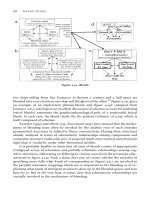
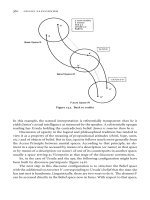
FIGURE 7.21 Types of angle joints and methods of reducing cleavage.
11
FIGURE 7.22 Reinforcement of bonded corner joints.
FIGURE 7.23 Methods of joining flexible rub-
ber or plastic.
11
Downloaded from Digital Engineering Library @ McGraw-Hill (www.digitalengineeringlibrary.com)
Copyright © 2006 The McGraw-Hill Companies. All rights reserved.
Any use is subject to the Terms of Use as given at the website.
PLASTICS JOINING
7.36 CHAPTER 7
Table 7.10 lists common recommended surface treatments for plastic adherends. These
treatments are necessary when plastics are to be joined with adhesives. Specific surface
treatments for certain plastics and their effect on surface property characteristics are dis-
cussed in Sec. 7.6. Details regarding the surface treatment process parameters may also be
found in ASTM D-2093 and various texts on adhesive bonding of plastics. An excellent
source of information regarding prebond surface treatments is the supplier of the plastic
resin that is being joined.
Chemical or physical surface treatments are especially required for structural bonding
of low-surface-energy plastics. Low-surface-energy plastics include polyethylene,
polypropylene, TPO, and fluorinated polymers. These surface treatments are designed to
increase the critical surface tension and improve wetting and adhesion. In addition to in-
creasing the critical surface tension, surface treatments are designed to remove contami-
nants or “weak boundary layers,” such as a mold release.
Abrasion and solvent cleaning are generally recommended as a surface treatment for
high-surface-energy thermoplastics and for thermosetting plastics. Frequently, a mold-re-
lease agent is present and must be removed before adhesive bonding. Mold-release agents
are usually removed by a detergent wash, solvent wash, or solvent wipe.
Common solvents used to clean plastic surfaces for adhesive bonding are acetone, tolu-
ene, trichloroethylene, methyl ethyl ketone (MEK), low-boiling petroleum ether, and iso-
propanol. A solvent should be selected that does not affect the plastic surface but is
sufficiently strong to remove organic contamination. Safety and environmental factors
must be considered when choosing a solvent. Solvent cleaning alone can be used for high-
surface-energy plastics that do not require the maximum joint strength.
The compatibility of cleaning solvents with plastic substrates is extremely important.
Solvents can affect polymeric surfaces and provide unacceptable part appearance or even
degradation of properties. Solvents that are recommended for cleaning plastics are shown
in Table 7.11. Suppliers of mold release agents are the best source for information on sol-
vents that will remove their materials.
Abrasive treatments consist of scouring, machining, hand sanding, and dry and wet
abrasive blasting. The abrasive medium can be fine sandpaper, carborundum or alumina
abrasives, metal wools, or abrasive shot. Mechanical abrasion is usually preceded and fol-
lowed by solvent cleaning. The choice is generally determined by available production fa-
cilities and cost.
Laminates can be prepared by either abrasion or the tear-ply technique. In the tear-ply
design, the laminate is manufactured so that one ply of heavy fabric, such as Dacron,
glass, or the equivalent, is attached at the bonding surface. Just prior to bonding, the tear-
ply is stripped away, and a fresh, clean, bondable surface is exposed.
Chemical surface treatments vary with the type of plastic being bonded. These pro-
cesses can involve the use of corrosive and hazardous materials. The most common pro-
cesses are sulfuric acid–sodium dichromate etch (polyolefins) and sodium-naphthalene
etch (fluorocarbons). Both of these processes are described in ASTM D-2093.
Flame, hot air, electrical discharge, and plasma treatments change the surface of the
polymer both physically and chemically. The plasma treating process has been found to be
very successful on most low-energy surface plastics. Table 7.12 shows that plasma treat-
ment results in improved plastic joint strength with common epoxy adhesive. Plasma treat-
ment requires vacuum and special batch processing equipment.
Most optimized surface treatment processes require prolonged production time and
provide safety and environmental concerns. One should be careful not to overspecify the
surface treatment required. Only the minimal process necessary to accomplish the func-
tional objectives of the application is required.
Several new surface treatments and modifications of older, conventional surface treat-
ments have been introduced over the last few years to provide alternatives to the common
Downloaded from Digital Engineering Library @ McGraw-Hill (www.digitalengineeringlibrary.com)
Copyright © 2006 The McGraw-Hill Companies. All rights reserved.
Any use is subject to the Terms of Use as given at the website.
PLASTICS JOINING
PLASTICS JOINING 7.37
Downloaded from Digital Engineering Library @ McGraw-Hill (www.digitalengineeringlibrary.com)
Copyright © 2006 The McGraw-Hill Companies. All rights reserved.
Any use is subject to the Terms of Use as given at the website.
PLASTICS JOINING
Downloaded from Digital Engineering Library @ McGraw-Hill (www.digitalengineeringlibrary.com)
Copyright © 2006 The McGraw-Hill Companies. All rights reserved.
Any use is subject to the Terms of Use as given at the website.
PLASTICS JOINING
Downloaded from Digital Engineering Library @ McGraw-Hill (www.digitalengineeringlibrary.com)
Copyright © 2006 The McGraw-Hill Companies. All rights reserved.
Any use is subject to the Terms of Use as given at the website.
PLASTICS JOINING
Downloaded from Digital Engineering Library @ McGraw-Hill (www.digitalengineeringlibrary.com)
Copyright © 2006 The McGraw-Hill Companies. All rights reserved.
Any use is subject to the Terms of Use as given at the website.
PLASTICS JOINING
Downloaded from Digital Engineering Library @ McGraw-Hill (www.digitalengineeringlibrary.com)
Copyright © 2006 The McGraw-Hill Companies. All rights reserved.
Any use is subject to the Terms of Use as given at the website.
PLASTICS JOINING
7.42 CHAPTER 7
processes noted above. The driving factors for these developments have primarily been re-
lated to environment and safety. Harsh chemicals and elevated-temperature processing as-
sociated with conventional chemical and flame treatment methods have inhibited many
from using such processes.
TABLE 7.11 Common Degreasing Solvents for Polymeric Surfaces
13
Adherend Solvent
Acetal (copolymer) Ketone
Acetal (homopolymer) Ketone
Acrylonitrile-butadiene-styrene Ketone
Cellulose, cellulose acetate, cellulose acetate butyrate, cellulose
nitrate
Alcohol
Fluorocarbons Chlorinated alcohol or ketone
Polyamide (nylon) Ketone
Polycarbonate Alcohol
Polyolefins Ketone
Polyethylene terephthalate, PET (Mylar) Ketone
Polyimide Ketone
Polymethylmethacrylate, methacrylate butadiene Ketone or alcohol
Polyphenylene oxide Alcohol
Polyphenylene sulfide Ketone, chlorinated solvents
Polystyrene Alcohol
Polyvinyl chloride, polyvinyl fluoride Ketone, chlorinated solvents
Thermoplastic polyester Ketone
Thermoset plastics Ketone
TABLE 7.12 Typical Adhesive Strength Improvement with Plasma
Treatment: Aluminum-to-Plastic Shear Specimen Bonded with a
Conventional Epoxy Adhesive
15
Plastic
Strength of bond, psi
Control After plasma treatment
Polyamide 846 >3956
Polyethylene 315 >3125
Polyethylene terephthalate 530 1660
Polypropylene 370 3080
Polystyrene 566 >4015
Polytetrafluoroethylene 75 750
Polyvinyl fluoride 278 >1280
Downloaded from Digital Engineering Library @ McGraw-Hill (www.digitalengineeringlibrary.com)
Copyright © 2006 The McGraw-Hill Companies. All rights reserved.
Any use is subject to the Terms of Use as given at the website.
PLASTICS JOINING
PLASTICS JOINING 7.43
In addition to providing safer and environmentally friendly processes, these newer sur-
face treatments have also been shown to provide for easier and faster processing. They
promise a potentially tremendous positive impact on both manufacturing cost and perfor-
mance properties. The reduced cost impact can be in the form of equipment costs, imple-
mentation costs, operational costs, rework costs and storage/waste removal costs.
7.4.6 Adhesives Selection
Factors most likely to influence adhesive selection are listed in Table 7.13. However, ther-
mosetting adhesives such as epoxies, polyurethanes, or acrylics are commonly used for
structural application. The adhesive formulations are generally tough, flexible compounds
that can cure at room temperature. The reasons that these adhesives have gained most pop-
ularity in bonding of plastics are summarized in this section.
The physical and chemical properties of both the solidified adhesive and the plastic
substrate affect the quality of the bonded joint. Major elements of concern in selecting an
adhesive for plastic parts are the thermal expansion coefficient and glass transition temper-
ature of the substrate relative to the adhesive. Special consideration is also required of
polymeric surfaces that can change during normal aging or exposure to operating environ-
ments.
Significant differences in thermal expansion coefficient between substrates and the ad-
hesive can cause serious stress at the plastic’s joint interface. These stresses are com-
pounded by thermal cycling and low-temperature service requirements. Selection of a
resilient adhesive or adjustments in the adhesive’s thermal expansion coefficient via filler
or additives can reduce such stress.
Downloaded from Digital Engineering Library @ McGraw-Hill (www.digitalengineeringlibrary.com)
Copyright © 2006 The McGraw-Hill Companies. All rights reserved.
Any use is subject to the Terms of Use as given at the website.
PLASTICS JOINING
7.44 CHAPTER 7
Structural adhesives must have a glass transition temperature higher than the operating
temperature to avoid a cohesively weak bond and possible creep problems. Modern engi-
neering plastics, such as polyimide or polyphenylene sulfides, have very high glass transi-
tion temperatures. Most common adhesives have a relatively low glass transition
temperature so that the weakest thermal link in the joint may often be the adhesive.
Use of an adhesive too far below its glass transition temperature could result in low
peel or cleavage strength. Brittleness of the adhesive at very low temperatures could also
manifest itself in poor impact strength.
Generally, the best adhesive is one that will wet the substrate and, when cured, has a
modulus and thermal expansion coefficient similar to the substrate or else has necessary
toughness and elongation to accommodate stresses caused by thermal movements. Differ-
ences in flexibility or thermal expansion between the adherends or between the adhesive
and adherend can introduce internal stresses into the bond line. Such stresses can lead to
premature failure of a bond. Thus, rigid, heavily filled adhesives are often chosen for
bonding metals.
Flexible adhesives are often chosen for bonding plastics and elastomers. Lower-modu-
lus adhesives generally have the flexibility to bond well to plastic substrates. However,
these are generally weaker in shear than more rigid adhesives. Fortunately, exceptionally
high shear strength is often not required for an adhesive for plastic, since the plastic sub-
strate itself is relatively weak.
For many high-surface-energy thermosetting plastics, such as epoxies, polyesters, and
phenolics, adhesive bonding is generally easy and can be accomplished with many of the
same adhesives that are used on metal substrates. For thermoplastics, the surface energy is
generally lower, the reactivity is greater, and the thermal expansion is higher than for ther-
mosets. Therefore, when bonding thermoplastics, consideration must be given to the sur-
face energy of the adhesive and the substrate, the compatibility of the adhesive with the
substrate, and thermal expansion coefficients.
There are numerous families of adhesives within the structural and nonstructural types.
The most common chemical families of structural and nonstructural adhesive families for
bonding plastics are identified in Table 7.14.
Structural adhesives are those having bond shear strength on the order of 1000 psi or
greater. This is often sufficient to cause failure of the plastic substrate when the bond is
TABLE 7.14 Common Families of Structural and Non-
structural Adhesives for Bonding Plastics
Structural adhesives for bonding plastics
• Cyanoacrylate
• Epoxy
• Polyurethane
• Reactive acrylic
• Light curing adhesive (acrylic and cyanoacrylate)
Nonstructural adhesives for bonding plastics
• Synthetic and natural elastomers
• Thermoplastic hot melts
• Resin latex adhesives
• Silicone
Downloaded from Digital Engineering Library @ McGraw-Hill (www.digitalengineeringlibrary.com)
Copyright © 2006 The McGraw-Hill Companies. All rights reserved.
Any use is subject to the Terms of Use as given at the website.
PLASTICS JOINING
PLASTICS JOINING 7.45
tested. Structural adhesives are generally intended for applications where chemical and
temperature resistance are requirements, as well as high strength and toughness.
Nonstructural adhesives are those having bond strength that is less than 1000 psi but
sufficient for applications such as pressure sensitive tapes, labels, laminates, and so on.
Nonstructural adhesives are usually employed where production speed, convenience, and
high peel strength are required. They generally have sufficient permanence for the applica-
tions mentioned.
In selecting an adhesive system for a plastic, it is important to remember that the adhe-
sive must retain its initial strength during the life of the product. Often plastics substrates
can chemically and/or physically change during service aging. Therefore, the choice of the
adhesive must be adequate for resisting initial as well as long-term stress conditions.
Plastic substrates could be chemically active, even when isolated from the operating
environment. Many polymeric surfaces slowly undergo chemical and physical change.
The plastic surface, at the time of bonding, may be well suited to the adhesive process.
However, after aging, undesirable surface conditions may present themselves at the inter-
face, displace the adhesive, and result in bond failure. These weak boundary layers may
come from the environment or within the plastic substrate itself.
Moisture, solvent, plasticizers, and various gases and ions can compete with the cured
adhesive for bonding sites. The process by which a weak boundary layer preferentially
displaces the adhesive at the interface is called desorption. Moisture is the most common
desorbing substance, being present both in the environment and within many polymeric
substrates.
Solutions to the desorption problem consist of eliminating the source of the weak
boundary layer or selecting an adhesive that is compatible with the desorbing material.
Excessive moisture can be eliminated from a plastic part by postcuring or drying the part
before bonding. Additives that can migrate to the surface can possibly be eliminated by re-
formulating the plastic resin. Also, certain adhesives are more compatible with oils and
plasticizer than others. For example, the migration of plasticizer from flexible polyvinyl
chloride can be counteracted by using nitrile-based adhesives. Nitrile adhesives resins are
capable of absorbing the plasticizer without degradation.
7.4.7 The Adhesives Bonding Processes
After the adhesive is applied, the assembly must be mated as quickly as possible to prevent
contamination of the adhesive surface. The substrates are held together under pressure and
heated if necessary until cure is achieved. The equipment required to perform these func-
tions must provide adequate heat and pressure, maintain constant pressure during the en-
tire cure cycle, and distribute pressure uniformly over the bond area. Of course, many
adhesives cure with simple contact pressure at room temperature, and extensive bonding
equipment is not necessary.
Pressure devices should be designed to maintain constant pressure on the bond during
the entire cure cycle. They must compensate for thickness reduction from adhesive flow-
out or thermal expansion of assembly parts. Thus, screw-actuated devices like C-clamps
and bolted fixtures are not acceptable when constant pressure is important. Spring pressure
can often be used to supplement clamps and compensate for thickness variations. Dead-
weight loading may be applied in many instances; however, this method is sometimes im-
practical, especially when heat cure is necessary.
Pneumatic and hydraulic presses are excellent tools for applying constant pressure.
Steam or electrically heated platen presses with hydraulic rams are often used for adhesive
bonding. Some units have multiple platens, thereby permitting the bonding of several as-
semblies at one time.
Downloaded from Digital Engineering Library @ McGraw-Hill (www.digitalengineeringlibrary.com)
Copyright © 2006 The McGraw-Hill Companies. All rights reserved.
Any use is subject to the Terms of Use as given at the website.
PLASTICS JOINING
7.46 CHAPTER 7
Many structural adhesives require heat as well as pressure. Most often the strongest
bonds are achieved by an elevated-temperature cure. With many adhesives, trade-offs be-
tween cure times and temperature are permissible. But generally, the manufacturer will
recommend a certain curing schedule for optimum properties.
However, often the temperature required to cure the adhesive will adversely affect
heat-sensitive plastic parts. Also, heat-curing adhesives are generally more rigid than those
that cure at room temperature, and the resulting modulus is too high for many plastic-
bonding applications. As a result, most adhesives recommended for bonding plastic sub-
strates cure at room temperature.
It is highly desirable to have a uniformly thin (2- to 10-mil) adhesive bond line. Starved
adhesive joints, however, will yield exceptionally poor properties. Three basic methods are
used to control adhesive thickness. The first method is to use mechanical shims or stops,
which can be removed after the curing operation. Sometimes it is possible to design stops
into the joint.
The second method is to employ a film adhesive that becomes highly viscous during
the cure cycle, preventing excessive flow-out. With supported films, the adhesive carrier it-
self can act as the “shims.” Generally, the cured bond-line thickness will be determined by
the original thickness of the adhesive film. The third method of controlling adhesive thick-
ness is to use trial and error to determine the correct pressure-adhesive viscosity factors
that will yield the desired bond thickness.
7.4.8 Quality Control
Quality control systems and procedures are a requirement in almost every bonding appli-
cation. Quality control should cover all phases of the bonding cycle from inspection of in-
coming material to the inspection of the completed assembly. In fact, good quality control
will start even before receipt of materials. Quality control will encompass, at a minimum:
• Specification and inspection of incoming adherends as well as adhesives
• Control over the surface preparation process
• Control over the bond fabrication process (equipment, temperature, pressure, time, and
so on)
• Inspection of the final part (destructively or nondestructively)
• Training of personnel in all aspects of adhesive bonding as well as safety and health re-
quirements
The human element enters the adhesive-bonding process more than in other fabrication
techniques. An extremely high percentage of defects can be traced to poor workmanship.
This generally prevails in the surface-preparation steps but may also arise in any of the
other steps necessary to achieve a bonded assembly. This problem can be largely over-
come by proper motivation and education. All employees from design engineer to laborer
to quality-control inspector should be somewhat familiar with adhesive bonding technol-
ogy and be aware of the circumstances that can lead to poor joints. A great many defects
can also be traced to poor design engineering.
The plant’s bonding area should be as clean as possible prior to receipt of materials.
The basic approach to keeping the assembly area clean is to segregate it from the other
manufacturing operations either in a corner of the plant or in isolated rooms. The air
should be dry and filtered to prevent moisture or other contaminants from gathering at a
possible interface. The cleaning and bonding operations should be separated from each
Downloaded from Digital Engineering Library @ McGraw-Hill (www.digitalengineeringlibrary.com)
Copyright © 2006 The McGraw-Hill Companies. All rights reserved.
Any use is subject to the Terms of Use as given at the website.
PLASTICS JOINING
PLASTICS JOINING 7.47
other. If mold release is used to prevent adhesive flash from sticking to bonding equip-
ment, it is advisable that great care be taken to assure that the release does not contaminate
the adhesive or the adherends. Spray mold releases, especially silicone release agents,
have a tendency to migrate to undesirable areas.
Acceptance tests on adhesives should be directed toward assurance that incoming ma-
terials are identical from lot to lot. The tests should be those that can quickly and accu-
rately detect deficiencies in the adhesive’s physical or chemical properties. A number of
standard tests for adhesive bonds and for adhesive acceptance have been specified by the
American Society for Testing and Materials (ASTM). The properties usually reported by
adhesive suppliers are ASTM tensile-shear (ASTM D-1002) and peel strength (ASTM D-
903, D-1876, and D-3167).
Actual test specimens should also be made to verify strength of the adhesive. These
specimens should be stressed in directions that are representative of the forces that the
bond will see in service, i.e., shear, peel, tension, or cleavage. If possible, the specimens
should be prepared and cured in the same manner as actual production assemblies. If time
permits, specimens should also be tested in simulated service environments, e.g., high
temperature and humidity.
Surface preparations must be carefully controlled for reliable production of adhesive-
bonded parts. If a chemical surface treatment is required, the process must be monitored
for proper sequence, bath temperature, solution concentration, and contaminants. If sand
or grit blasting is employed, the abrasive must be changed regularly. An adequate supply
of clean wiping cloths for solvent cleaning is also mandatory. Checks should be made to
determine if cloths or solvent containers may have become contaminated.
The adhesive metering and mixing operation should be monitored by periodically sam-
pling the mixed adhesive and testing it for adhesive properties. A visual inspection can
also be made for air entrapment and degree of mixing. The quality-control engineer should
be sure that the oldest adhesive is used first and that the specified shelf life has not been
exceeded.
During the actual assembly operation, the cleanliness of the shop and tools should be
verified. The shop atmosphere should be controlled as closely as possible. Temperature is
in the range of 18 to 32°C and relative humidity from 20 to 65 percent is best for almost all
bonding operations.
The amount of the applied adhesive and the final bond-line thickness must also be
monitored, because they can have a significant effect on joint strength. Curing conditions
should be monitored for heat-up rate, maximum and minimum temperature during cure,
time at the required temperature, and cool-down rate.
After the adhesive is cured, the joint area can be inspected to detect gross flaws or de-
fects. This inspection procedure can be either destructive or nondestructive in nature. De-
structive testing generally involves placing samples of the production run in simulated or
accelerated service and determining if it has similar properties to a specimen that is known
to have a good bond and adequate service performance. The causes and remedies for faults
revealed by such mechanical tests are described in Table 7.15.
Nondestructive testing (NDT) is far more economical, and every assembly can be
tested if desired. However, there is no single nondestructive test or technique that will pro-
vide the user with a quantitative estimate of bond strength. There are several ultrasonic test
methods that provide qualitative values. However, a trained eye can detect a surprising
number of faulty joints by close inspection of the adhesive around the bonded area. Table
7.16 lists the characteristics of faulty joints that can be detected visually. The most difficult
defects to be found by any method are those related to improper curing and surface treat-
ments. Therefore, great care and control must be given to surface-preparation procedures
and shop cleanliness.
Downloaded from Digital Engineering Library @ McGraw-Hill (www.digitalengineeringlibrary.com)
Copyright © 2006 The McGraw-Hill Companies. All rights reserved.
Any use is subject to the Terms of Use as given at the website.
PLASTICS JOINING
7.48 CHAPTER 7
Downloaded from Digital Engineering Library @ McGraw-Hill (www.digitalengineeringlibrary.com)
Copyright © 2006 The McGraw-Hill Companies. All rights reserved.
Any use is subject to the Terms of Use as given at the website.
PLASTICS JOINING
PLASTICS JOINING 7.49
7.5 WELDING
Certain thermoplastic substrates may be joined by methods other than mechanical fasten-
ing or adhesive bonding. Welding is particularly attractive for thermoplastics, because
joining times are often very short, enabling high throughput. Also, the various welding
processes typically provide strong joints, tolerate contaminated surfaces, and successfully
join such difficult to bond substrates as polyethylene, polypropylene, and nylon.
Welding processes are of two main types: thermal and solvent. By careful application
of heat or solvent to a thermoplastic substrate, one may liquefy the surface resin and use it
to form the bond. The bond strength is determined by diffusion of polymer from one sur-
face into another instead of by the wetting and adsorption of an adhesive layer. It is possi-
ble to weld plastics of different types. However, for both thermal and solvent welding, the
success of the process will be heavily determined by the compatibility of the polymers be-
ing joined.
With thermal or solvent welding, surface preparation is not as critical as with adhesive
bonding. However, some form of surface pretreatment may still be necessary, although
difficult chemical or physical treatments to increase the surface energy are not required.
Certainly, the parts should be clean, and all mold release and contaminants must be re-
moved by standard cleaning procedures.
Downloaded from Digital Engineering Library @ McGraw-Hill (www.digitalengineeringlibrary.com)
Copyright © 2006 The McGraw-Hill Companies. All rights reserved.
Any use is subject to the Terms of Use as given at the website.
PLASTICS JOINING
7.50 CHAPTER 7
It may also be necessary to dry certain polymeric parts, such as nylon and polycarbon-
ate, before welding so that the inherent moisture in the part will not affect the overall qual-
ity of the bond. It may also be necessary to thermally anneal parts, such as acrylic, before
solvent welding to remove or lessen internal stresses caused by molding. Without anneal-
ing, the stressed surface may crack or craze when in contact with solvent.
7.5.1 Thermal Welding
Welding by application of heat, or “thermal welding,” provides an advantageous method
of joining many thermoplastics that do not degrade rapidly at their melt temperature. It is a
method of providing fast, relatively easy, and economical bonds that are generally 80 to
100 percent of the strength of the parent plastic. In all thermal welding processes, the sub-
strate surface is heated by some method until it is at a melt or flowable state. The melted
surfaces are then pressed together (forged), which results in interdiffusion of the molecular
chains. On cooling to a solid state, a strong and permanent joint is created.
Thermal welding process can be of two kinds: direct and indirect. Each kind of thermal
welding may be further classified, as shown below, according to the method used to pro-
vide heat.
Direct Thermal Welding Processes
• Heated tool welding
• Hot gas welding
• Other (infrared radiation, laser, and others)
Indirect Thermal Welding Processes
• Friction or spin welding
• Induction welding
• Ultrasonic and vibration welding
• Dielectric welding
With direct welding, the heat is applied directly to the substrate in the form of either a
heated tool or hot gas. Indirect heating occurs when some form of energy other than ther-
mal is applied to the joint. The applied energy, which causes heating at the interface or in
the plastic as a whole, is generally in the form of friction, high-frequency electrical fields,
electromagnetic fields, or ultrasonic vibration. Because the heating is localized at the
bonding surface, indirect heating processes are very energy efficient, generally resulting in
bonds that are stress free and of higher strength than those made by direct welding meth-
ods.
7.5.1.1 Heated Tool Welding. With this method, the surfaces to be fused are heated by
holding them against a hot metal surface (232 to 371°C); then the parts are brought into
contact and allowed to harden under slight pressure (5 to 15 psi). Electric strip heaters,
soldering irons, hot plates, and resistance blades are common methods of providing heat.
Heated platens are generally employed to create a molten or plasticized region. Thus, this
form of welding is often called hot-plate welding.
One production technique involves butting flat plastic sheets on a table next to an elec-
trical resistance heated blade that runs the length of the sheet. Once the plastic adjacent to
the blade begins to soften, the blade is raised, and the sheets are pressed together and held
under pressure while they cool. The heated metal surfaces are usually coated with a high-
Downloaded from Digital Engineering Library @ McGraw-Hill (www.digitalengineeringlibrary.com)
Copyright © 2006 The McGraw-Hill Companies. All rights reserved.
Any use is subject to the Terms of Use as given at the website.
PLASTICS JOINING
PLASTICS JOINING 7.51
temperature release coating such as polytetrafluoroethylene to discourage sticking to the
molten plastic.
Successful heated tool welding depends on the temperature of the heated tool surface,
the amount of time the plastic adherends are in contact with the hot tool, the time lapse be-
fore joining the substrates, and the amount and uniformity of pressure that is held during
cooling. Heated tool welding can be used for structural plastic parts, and heat sealing can
be used for plastic films. With heat sealing, the hot surface is usually hot rollers or a heated
rotating metal band commonly used to seal plastic bags. Table 7.17 offers heat welding
temperatures for a number of common plastics and films.
Resistance wire or implant welding is also a type of heated tool welding. This method
generally employs an electrical resistance heating wire laid between mating substrates to
generate the heat of fusion. When energized, the wire undergoes resistance heating and
causes a melt area to form around the adjacent polymer. Pressure on the parts during this
process causes the molten material to flow and act as a hot-melt adhesive for the joint. Af-
ter the bond has been made and the joint solidifies, the resistance wire material is generally
cut off and removed.
Resistance wire welding can be used on any plastic that can be joined effectively by
heated tool welding. The process is typically applied to relatively large structures. Con-
tacting the plastic resin manufacturer for details concerning the specific parameters of this
process is recommended.
Radio-frequency energy has also been used to heat an implant that is placed at the joint
interface. Current passing through the conductive implant generates the heat in this pro-
cess. Once the joint is made, the implant can be reheated via radio-frequency heating and
the parts can be disassembled. Thus, this welding process is popular for applications
where recovery or efficient disassembly of parts is critical.
Downloaded from Digital Engineering Library @ McGraw-Hill (www.digitalengineeringlibrary.com)
Copyright © 2006 The McGraw-Hill Companies. All rights reserved.
Any use is subject to the Terms of Use as given at the website.
PLASTICS JOINING
7.52 CHAPTER 7
The resistive element can be any material that conducts current, including metal wires
and braids and carbon-based compounds. Implant materials should be compatible with the
intended application, since they will remain in the bondline.
7.5.1.2 Hot Gas welding. In hot gas welding, the weld joint is filled with a partially or
fully molten polymer. This process is often used for long bond lines and for outdoor appli-
cations where it is difficult to control conditions. Common applications are the bonding of
pond liners, repair of large thermoplastic tanks, assembly of large air ducts, and the join-
ing of pipe.
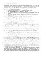
In the most common hot gas welding process, an electrically or gas heated welding gun
with an orifice temperature of 218 to 371°C can be used to bond many thermoplastic mate-
rials. The pieces to be bonded are beveled and positioned to form a V-shaped joint as
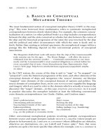
shown in Figure 7.24. A welding rod, made of the same plastic that is being bonded, is laid
into the joint, and the heat from the gun is directed at the interface of the substrates and the
rod. The molten product from the welding rod then fills the gap. A strong fillet must be
formed, the design of which is of considerable importance.
A large difference between the plastic melting temperature and the decomposition tem-
perature of the plastic is necessary for consistent, reliable hot gas welding results. Usually,
the hot gas can be common air. However, for polyolefins and other easily oxidized plastics,
the heated gas must be inert or nitrogen, since air will oxidize the surface of the plastic.
After welding, the joint should not be stressed for several hours. This is particularly
true for polyolefins and nylons. Hot gas welding is not recommended for filled materials
or substrates of less than 1/16 in thickness. Applications are usually large structural assem-
blies. The weld is not cosmetically attractive, but tensile strengths that are 85 percent of
the parent materials are easily obtained.
A similar type of welding to hot gas welding is extrusion welding. In extrusion weld-
ing, a fully molten polymer is injected into the weld joint. The molten polymer is gener-
ated inside the welding tool or extrusion equipment and then pumped into the weld joint as
the tool is moved along the weld.
7.5.1.3 Friction or Spin Welding. Spin welding uses the heat of friction to cause fusion
at the interface. One substrate is rotated very rapidly while in touch with the other station-
ary substrate so that the surfaces melt without damaging the part. Sufficient pressure is ap-
plied during the process to force out excess air bubbles. The rotation is then stopped, and
FIGURE 7.24 Hot gas welding ap-
paratus.
Downloaded from Digital Engineering Library @ McGraw-Hill (www.digitalengineeringlibrary.com)
Copyright © 2006 The McGraw-Hill Companies. All rights reserved.
Any use is subject to the Terms of Use as given at the website.
PLASTICS JOINING
PLASTICS JOINING 7.53
pressure is maintained until the weld sets. Rotation speed and pressure are dependent on
the thermoplastics being joined.
The main process parameters are the spin of rotation, weld or axial pressure, and weld
time. The equipment necessary depends on production requirement, but spin welding can
be adapted to standard shop machinery such as drill presses or lathes. In commercial spin
welding machines, rotational speeds can range from 200 to 14,000 rpm. Welding times
(heating and cooling) can range from less than 1 to 20 s, with typical times being several
seconds.
A wide variety of joints can be made by spin welding. Since the outer edges of the ro-
tating substrate move considerably faster than the center, joints are generally designed to
concentrate pressure at the center. Hollow sections with thin walls are the best joint de-
signs for this welding method, since the differential generation of heat could result in high
weld zone stresses. A shallow tongue-and-groove type of joint design is also useful to in-
dex the opposite parts and provide a uniform bearing surface.
Because of its high weld quality, simplicity, speed, and reproducibility, spin welding is a
popular method of joining large-volume products, packaging, and toys. Common applica-
tions are the manufacture of floats, aerosol bottles, and attachment of studs to plastic parts.
7.5.1.4 Induction Heating. An electromagnetic induction field can be used to heat a
metal grid or an insert placed between mating thermoplastic substrates (see implant weld-
ing, above). When the joint is positioned between energized induction coils, the hot insert
material responds to the high-frequency AC source, causing the plastic surrounding it to
melt and fuse together. Slight pressure is maintained as the induction field is turned off and
the joint hardens.
In addition to metal inserts, electromagnetic adhesives can be used to form the joint.
Electromagnetic adhesives are made from metal or ferromagnetic particle-filled thermo-
plastics. These adhesives can be shaped into gaskets or film that can easily be applied and
will melt in an induction field.
18
The advantage of this method is that stresses caused by
large metal inserts are avoided.
Induction welding is less dependent than other welding methods on the properties of
the materials being welded. It can be used on nearly all thermoplastics. In welding differ-
ent materials, the thermoplastic resin enclosing the metal particles in the electromagnetic
adhesive is made of a blend of the materials being bonded. Table 7.18 shows compatible
combinations for electromagnetic adhesives. Reinforced plastics with filler levels over 50
percent have been successfully electromagnetically welded.
Downloaded from Digital Engineering Library @ McGraw-Hill (www.digitalengineeringlibrary.com)
Copyright © 2006 The McGraw-Hill Companies. All rights reserved.
Any use is subject to the Terms of Use as given at the website.
PLASTICS JOINING
7.54 CHAPTER 7
Strong and clean structural, hermetic, and high-pressure seals can be obtained from this
process. Important determinants of bond quality in induction welding are the joint design
and induction coil design. With automatic equipment, welds can be made in less than 1 s.
7.5.1.5 Ultrasonic and Vibration Welding. Ultrasonic welding is a well accepted
method for joining high-volume, relatively small plastic parts. Energy for vertical oscilla-
tions produces intense frictional heating between two substrates. This frictional heating
produces sufficient thermal energy to rapidly generate a molten weld zone.
During ultrasonic welding, a high-frequency (20 to 40 kHz) electrodynamic field is
generated that resonates a metal horn. The horn is in contact with one of the plastic parts,
and the other part is fixed firmly. The horn and the part to which it is in contact vibrate suf-
ficiently fast to cause great heat at the interface of the parts being bonded. With pressure
and subsequent cooling, a strong bond can be obtained with many thermoplastics.
The basic variables in ultrasonic bonding are amplitude, air pressure, weld time, and
hold time. The desired joint strength can be achieved by altering these variables. Increas-
ing weld time generally results in increasing bond strength up to a point. After that point,
additional weld time does not improve the joint and can even degrade it. Average process-
ing times, including welding and cooling, are less than several seconds.
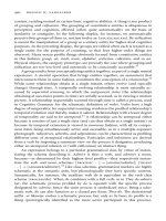
Typical ultrasonic joint designs are shown in Figure 7.25. Usually, an energy director,
or small triangular tip in one of the parts, is necessary. All of the ultrasonic energy is con-
centrated on the tip of the energy director, and this is the area of the joint that then heats,
melts, and provides the material for the bond. Ultrasonic welding is considered a faster
means of bonding than direct heat welding.
Ultrasonic welding of parts fabricated from ABS, acetals, nylon, PPO, polycarbonate,
polysulfone, and thermoplastic polyesters should be considered as early in the design of
the part as possible. Very often, minor modifications in part design will make ultrasonic
welding more convenient. The plastic resin manufacturer or ultrasonic equipment supplier
can recommend best joint design and ultrasonic horn design.
FIGURE 7.25 Typical joint designs used in ultrasonic welding.
20
Downloaded from Digital Engineering Library @ McGraw-Hill (www.digitalengineeringlibrary.com)
Copyright © 2006 The McGraw-Hill Companies. All rights reserved.
Any use is subject to the Terms of Use as given at the website.
PLASTICS JOINING
PLASTICS JOINING 7.55
Like resin materials (such as ABS-to-ABS) are the easier to weld ultrasonically, but
some unlike resins may be bonded provided they have similar melt temperatures, chemical
composition, and modulus of elasticity. Generally, amorphous resins (ABS, PPO, and
polycarbonate) are also easier to weld ultrasonically than crystalline resins (nylon, acetal,
thermoplastic polyester).
Ultrasonic equipment can also be used for mechanical fastening operations. Ultrasonic
energy can be used to apply threaded inserts to molded plastic parts and to heat stake plas-
tic studs.
Vibration welding is similar to ultrasonic welding except that it uses a lower frequency
(120 to 240 Hz) of vibration. In this way, very large parts can be bonded. The two thermo-
plastic parts are rubbed together, under pressure and at a suitable frequency and amplitude,
until enough heat is generated at the joint interface to melt and diffuse the polymer sur-
faces.
The process parameters affecting the strength of the resulting weld are the amplitude
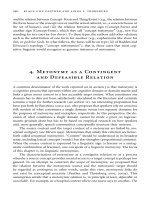
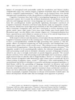
and frequency of motion, weld pressure, and weld time. There are two types of vibration
welding: linear, in which friction is generated by a linear motion of the parts, and orbital,
in which one part is vibrated using circular motion in all directions. Examples of these
processes are illustrated in Figure 7.26.
Vibration welding has been used on large thermoplastic parts such as canisters, pipe
sections, and other parts that are too large to be excited with an ultrasonic generator. An
advantage of vibration welding over ultrasonic welding is that it can provide gas-tight
joints in structures having long bond lines. Ultrasonic welding is basically a spot weld
technique limited by the size of the horn.
Total process time for vibration joining is generally between 5 and 15 s. This is longer
than spin or ultrasonic welding but much shorter than direct heat welding, solvent cement-
ing, or adhesive bonding. Vibration welding is applicable to most polymers, amorphous as
well as semicrystalline. It is particularly useful for the semicrystalline polymers that can-
not be easily welded using ultrasonic or solvent welding.
Vibration welding can be applied to ABS, acetal, nylon, PPO, thermoplastic polyesters,
and polycarbonate. For vibration welding, hydroscopic resins, such as nylon, do not have
to be dried as is necessary with ultrasonic welding. Joint designs do not require an energy
director as in ultrasonic joint designs, but the joint area must be strong enough to resist the
FIGURE 7.26 The vibration welding process. Linear vibration (left) is employed where
the length to width ratio precludes the use of axial welding (right) where the axial shift is
still within the width of the welded edge.
Downloaded from Digital Engineering Library @ McGraw-Hill (www.digitalengineeringlibrary.com)
Copyright © 2006 The McGraw-Hill Companies. All rights reserved.
Any use is subject to the Terms of Use as given at the website.
PLASTICS JOINING
7.56 CHAPTER 7
forces of operation without deformation. This often requires thickening the bond area or
designing stiffeners into the part near the joint areas.
7.5.1.6 Other Welding Methods. Dielectric welding can be used on most thermoplastics
except those that are relatively transparent to high-frequency electric fields. It is used
mostly to seal vinyl sheeting such as automobile upholstery, swimming pool liners, and
rainwear. An alternating electric field is imposed on the joint, which causes rapid reorien-
tation of polar molecules, and heat is generated by molecular friction. The field is re-
moved, and pressure is then applied and held until the weld cools.
Variable in the bonding operation are the frequency generated, dielectric loss of the
plastic, the power applied, pressure, and time. The frequency of the field being generated
can be from radio frequency up to microwave frequency. Dielectric heating can also be
used to generate the heat necessary for curing polar, thermosetting adhesives, or it can be
used to quickly evaporate water from water based adhesives—a common application in
the furniture industry.
Other thermal welding processes that are less common than those described above but
still used in industry are infrared welding and laser welding. These are generally used in
specialty processes or with applications that require unique methods of heating because of
the joint design or nature of the final product.
Infrared radiation (IR) is generally supplied by high-intensity quartz heat lamps. IR can
penetrate into a polymer without contact with the surface of the part. The depth of penetra-
tion depends on many factors, and it varies strongly with polymer formulation. Laser
welding is also a noncontact process for welding thermoplastics. Usually, a defocused la-
ser beam must be employed to avoid burning the polymer. High-speed (50 m/min) laser
welding of polyethylene films is one of several applications being explored.
7.5.2 Solvent Welding
Solvent welding or cementing is the simplest and most economical method of joining
many noncrystalline thermoplastics. Solvent welding is accomplished by applying solvent
to the bonding area between the two mating surfaces. The solvent dissolves the interface
area, resulting in molecular entanglement and diffusion between the mating surfaces. As
the solvent dissipates, the entanglement is effectively frozen in place.
Solvent cemented joints are less sensitive to thermal cycling than joints bonded with
adhesives, and they are as resistant to degrading environments as their parent plastic. Bond
strength equaling 85 to 100 percent of the parent plastic can be obtained. Solvent cements
also offers aesthetically pleasing bonds with reasonable assembly time and cost.
The major disadvantage of solvent cementing is the possibility of stress cracking or
crazing of the part and the possible hazards of using low-vapor-point solvents. When two
dissimilar plastics are to be joined, adhesive bonding is generally desirable because of sol-
vent and polymer compatibility problems.
Solvent cements should be chosen with approximately the same solubility parameter as
the plastic to be bonded. Table 7.19 lists typical solvents used to bond major plastics. The
solvent cement can be bodied to 25 percent by weight with the parent plastic to fill gaps
and reduce shrinkage and internal stress during cure.
It is common to use a mixture of fast-drying solvent with a less volatile solvent to pre-
vent crazing and to adjust drying times. With methylene chloride based solvents, glacial
acetic acid (3 percent) or diacetone alcohol (10 percent) can be added to retard the solvent
drying rate and reduce the effects of moisture during bonding.
Moisture is often an issue when solvent welding. Moisture absorbed by the solvent can
reduce its effectiveness during bonding. Solvent containers should be sealed to minimize
moisture absorption from the environment.
Downloaded from Digital Engineering Library @ McGraw-Hill (www.digitalengineeringlibrary.com)
Copyright © 2006 The McGraw-Hill Companies. All rights reserved.
Any use is subject to the Terms of Use as given at the website.
PLASTICS JOINING
PLASTICS JOINING 7.57
The parts to be bonded should be unstressed and, if necessary, annealed. The surfaces
should be smooth, mate well, and have tight tolerances. Although bodied cements will
provide gap filling properties, they should not be considered a final solution for poorly
matched parts.
A V-joint or rounded butt joint are generally preferred for making a solvent butt joint.
Scarf joints and flat butt joints are difficult to position and to apply pressure to during the
solvent evaporation phase of the process. Surfaces must also be clean. Any residual mold
release agents or mold polishing compounds can inhibit solvent bonding.
The solvent cement is generally applied to the substrate with a syringe or brush. In
some cases, the surface can be immersed in the solvent. After the area to be bonded soft-
ens, the parts are mated and held under pressure until dry. Pressure should be low and uni-
form so that the finished joint will not be stressed. After the joint hardens, the pressure is
released, and an elevated temperature cure may be necessary, depending on the plastic and
desired joint strength. The bonded part should not be packaged or stressed until the solvent
has adequate time to escape from the joint.
Proper ventilation and exhaust of the work area where solvents are used are critical for
obvious health, safety, and environmental concerns. Solvent vapors can also cause part
crazing and should be removed from the assembly area.
7.6 RECOMMENDED ASSEMBLY PROCESSES
FOR COMMON PLASTICS
When decisions are to be made relative to assembly methods (mechanical fastening, adhe-
sive bonding, thermal welding, or solvent cementing), special considerations must be
taken because of the nature of the substrate and possible interactions with the adhesive or
the environment. The following sections identify some of these considerations and offer an
assembly guide to the various methods of assemblies that have been found appropriate for
specific plastics.
Downloaded from Digital Engineering Library @ McGraw-Hill (www.digitalengineeringlibrary.com)
Copyright © 2006 The McGraw-Hill Companies. All rights reserved.
Any use is subject to the Terms of Use as given at the website.
PLASTICS JOINING
7.58 CHAPTER 7
7.6.1 Acetal Homopolymer and Acetal Copolymer
Parts made of acetal homopolymer and copolymer are generally strong and tough, with a
surface finish that is the mirror image of the mold surface. Acetal parts are generally ready
for end-use or further assembling with little or no post-mold finishing.
Press fitting has been found to provide joints of high strength at minimum cost. Acetal
copolymer can be used to provide snap-fit parts. Use of self-tapping screws may provide
substantial cost savings by simplifying machined parts and reducing assembly costs.
Epoxies, isocyanate cured polyester, and cyanoacrylates are used to bond acetal copol-
ymer. Generally, the surface is treated with a sulfuric-chromic acid treatment. Epoxies
have shown 150 to 500 psi shear strength on sanded surfaces and 500 to 1000 psi on chem-
ically treated surfaces. Plasma treatment has also been shown to be effective on acetal sub-
strates. Acetal homopolymer surfaces should be chemically treated prior to bonding. This
is accomplished with a sulfuric-chromic acid treatment followed by a solvent wipe. Ep-
oxies, nitrile, and nitrile-phenolics can be used as adhesives.
Thermal welding and solvent cementing are commonly used for bonding this material
to itself. Heated tool welding produces exceptionally strong joints with acetal homopoly-
mers and copolymers. With the homopolymer, a temperature of the heated surface near
288°C and a contact time of 2 to 10 s are recommended. The copolymer can be hot plate
welded from 221 to 293°C. Annealing acetal copolymer joints is claimed to strengthen
them further. Annealing can be accomplished by immersing the part in 175°C oil. Acetal
resin can be bonded by hot wire welding. Pressure on the joint, duration of the current, and
wire type and size must be varied to achieve optimum results. Shear strength on the order
of 150 to 300 lb/in or more have been obtained with both varieties, depending on the wire
size, energizing times (wire temperature), and clamping force.
Hot gas welding is used effectively on heavy acetal sections. Joints with 50 percent of
the tensile strength of the acetal resin have been obtained. Conditions of joint design and
rod placement are similar to those presented for ABS. A nitrogen blanket is suggested to
avoid oxidation. The outlet temperature of the welding gun should be approximately
332°C for the homopolymer and 293°C for the copolymer. For maximum joint strength,
both the welding rod and parts to be welded must be heated so that all surfaces are melted.
Acetal components can easily be joined by spin welding, which is a fast and generally
economical method to obtain joints of good strength. Spin welded acetal joints can have
straight 90° mating surfaces, or surfaces can be angles, molded in a V-shape, or flanged.
Although not common practice, acetal copolymer can be solvent welded at room tem-
perature with full-strength hexafluoroacetone sesquihydrate (Allied Chemical Corp., Mor-
ristown, NJ). The cement has been found to be an effective bonding agent for adhering to
itself, nylon, or ABS. Bond strengths in shear are greater than 850 psi using “as molded”
surfaces. Hexafluoroacetone sesquihydrate is a severe eye and skin irritant. Specific han-
dling recommendations and information on toxicity should be requested from Allied
Chemical Corp. Because of its high solvent resistance, acetal homopolymer cannot be sol-
vent cemented.
7.6.2 Acrylonitrile-Butadiene-Styrene (ABS)
ABS parts can be designed for snap-fit assembly using a general guideline of 5 percent al-
lowable strain during the interference phase of the assembly. Thread-cutting screws are
frequently recommended for nonfoamed ABS, and thread-forming screws for foamed
grades. Depending on the application, the use of bosses and boss caps may be advanta-
geous.
The best adhesives for ABS are epoxies, urethanes, thermosetting acrylics, nitrile-phe-
nolics, and cyanoacrylates. These adhesives have shown joint strength greater than that of
Downloaded from Digital Engineering Library @ McGraw-Hill (www.digitalengineeringlibrary.com)
Copyright © 2006 The McGraw-Hill Companies. All rights reserved.
Any use is subject to the Terms of Use as given at the website.
PLASTICS JOINING
PLASTICS JOINING 7.59
the ABS substrates being bonded. ABS substrates do not require special surface treatments
other than simple cleaning and removal of possible contaminants.
ABS can also be bonded to itself and to certain other thermoplastics by either solvent
cementing or any of the heat welding methods. For bonding acrylonitrile butadiene styrene
(ABS) to itself, it is recommended that the hot plate temperatures be between 221 to
287°C. Lower temperatures will result in sticking of the materials to the heated platens,
while temperatures above 287°C will increase the possibility of thermal degradation of the
surface. In joining ABS, the surfaces should be in contact with the heated tool until they
are molten, then brought carefully and quickly together and held with minimum pressure.
If too much pressure is applied, the molten material will be forced from the weld and re-
sult in poor appearance and reduced weld strength. Normally, if a weld flash greater than
1/8 in occurs, too much joining pressure has been used.
Hot gas welding has been used to join ABS thermoplastic with much success. Joints
with over 50 percent the strength of the parent material have been obtained. The ABS
welding rod should be held approximately at a 90° angle to the base material; the gun
should be held at a 45° angle with the nozzle 1/4 to 1/2 in from the rod. ABS parts to be
hot gas welded should be bonded at 60° angles. The welding gun, capable of heating the
gas to 260 to 315°C, must be moved continually in a fanning motion to heat both the weld-
ing rod and bed. Slight pressure must be maintained on the rod to insure good adhesion.
Spin welded ABS joints can have straight 90° mating surfaces, or surface can be an-
gled, molded in a V-shape, or flanged. The most important factor in the quality of the weld
is the joint design. The area of the spinning part should be as large as possible, but the dif-
ference in linear velocity between the maximum and minimum radii should be as small as
feasible.
One of the fastest methods of bonding ABS and acetal thermoplastics is induction
welding. This process usually takes 3 to 10 s but can be done in as little as 1 s. During
welding, a constant pressure of at least 100 psi should be applied on the joint to minimize
the development of bubbles; this pressure should be maintained until the joint has suffi-
ciently cooled. When used, metal inserts should be 0.02 to 0.04 in thick. Joints should be
designed to enclose completely the metal insert. Inserts made of carbon steel require less
power for heating, although other types of metal can be used. The insert should be located
as close as possible to the electromagnetic generator coil and centered within the coil to
assure uniform heating.
The solvents recommended for ABS are methyl ethyl ketone, methyl isobutyl ketone,
tetrahydrofuran, and methylene chloride. The solvent used should be quick drying to pre-
vent moisture absorption yet slow enough to allow assembly of the parts. The recom-
mended cure time is 12 to 24 hr at room temperature. The time can be reduced by curing at
55 to 65°C. A cement can be made by dissolving ABS resin in solvent up to 25 percent
solids. This type of cement is very effective in joining parts that have irregular surfaces or
areas that are not readily accessible. Because of the rapid softening actions of the solvent,
the pressure and amount of solvent applied should be minimal.
7.6.3 Cellulosics
Cellulosic materials (e.g., cellulose acetate, cellulose acetate butyrate, cellulose nitrate,
ethyl cellulose) can be mechanically fastened by a number of methods. However, their ri-
gidity and propensity to have internal molding stresses must be carefully considered.
Adhesives commonly used are epoxies, urethanes, isocyanate cured polyesters, nitrile-
phenolic, and cyanoacrylate. Only cleaning is required prior to applying the adhesive. A
recommended surface cleaner is isopropyl alcohol. Cellulosic plastics may contain plasti-
cizers. The extent of plasticizer migration and the compatibility with the adhesive must be
Downloaded from Digital Engineering Library @ McGraw-Hill (www.digitalengineeringlibrary.com)
Copyright © 2006 The McGraw-Hill Companies. All rights reserved.
Any use is subject to the Terms of Use as given at the website.
PLASTICS JOINING