Coatings of Polymers and Plastics Part 9 ppt
Bạn đang xem bản rút gọn của tài liệu. Xem và tải ngay bản đầy đủ của tài liệu tại đây (411.71 KB, 25 trang )
Performance and Durability Testing 189
adhesion, whereas applying it at a thickness greater than 15 microns, can lead
to cohesive failure within the adhesion promoter layer. The utilization of experi-
mental tools such as Time-of-Flight Secondary Ion Mass Spectroscopic (TOF-
SIMS) and fluorescent microscopy of labeled CPO (68) has led to the finding
that the CPO distributes itself within the top few microns of the TPO surface
and that the solvent composition of the adhesion promoter strongly influences
this. In some cases, CPO alone is not enough to ensure adequate adhesion to a
particular grade of TPO and auxiliary resins will be needed. Some polyolefin
diols (69) can be reacted with melamine to produce resins that can adhere di-
rectly to TPO and increase CPO adhesion.
Primers for higher surface energy plastics like RRIM and SMC are usually
of the polyester-melamine type. They usually contain flattener, filler, pigment,
and, if they will be exposed, UV fortification. Conductive carbon black is added
to ehnace the electrostatic attraction to the plastic part and quickly dissipate
any accumulated electrostatic charge (70,71). High electrical properties for both
adhesion promoters and primers are needed to optimize the paint’s application to
the plastic part and the subsequent topcoat. Measurement of the paint’s electrical
conductivity is crucial to optimize paint application performance including both
the amount of coverage and wrap. The highest electrical conductivity of a paint
film (or lowest resistivity) is achieved at the critical pigment volume concentra-
tion (CPVC) of the conductive pigment in the primer formulation (72). When
higher durability is needed or heat-sensitive plastics are used, then 2K primers
are used in which the melamine-formaldehyde crosslinker is basically replaced
by isocyanate to gain the level of cure needed at the lower temperature. How-
ever, 2K primers with high PVC carbon black content can consume isocyanate
and exhibit weaker adhesion on substrates such as ABS (73).
One of the primer formulating challenges is the balance of physical proper-
ties and cure after the primer bake cycle, especially when the product is considered
a weatherable primer. In that case, the primer needs to be designed to have out-
of-oven properties so that it is hard enough so that it can be sanded prior to
repainting and pass the required humidity, solvent-resistance, and humidity-adhe-
sion testing. In addition, the primer must be able to accept topcoat and ensure
good adhesion of the system after two bake cycles even though the type of bake
oven environment can dramatically influence adhesion of topcoat (74). Of course,
this is a nonissue for primers painted wet-on-wet with the topcoat. Many attempts
to formulate primers with the needed out-of-oven properties can exhibit adhesion
loss when topcoated. Careful selection of crosslinker and filler can usually over-
come this potential adhesion loss, even when the primer is severely overbaked.
6.2 Basecoats
Basecoat selection can influence finished part quality mostly through its selec-
tion of crosslinker. Some simple solventborne basecoats may be of the lacquer
190 Yaneff
type and do not contain any additional crosslinker. Typically one-component
(melamine-cured) basecoats require 121°C to fully cure whereas two-component
(usually isocyanate-cured) basecoats only require 75 to 82°C. Pigment differ-
ences can lead to dramatic differences between colors. Some pigments have
been surface treated and can contain acidic or basic groups that can alter the
degree of cure when external catalysts are used. Also the hiding properties of
the individual pigment can determine the amount of pigment needed to attain
the required color. Higher pigment to binder (P/B) coatings can exhibit undesir-
able issues that may not be seen with low P/B colors. It is important for the
formulator to understand the pigment contribution to film properties and perfor-
mance and only rely solely on the pigmentation offered from color development
personnel. A computer simulation capturing the physical aspects of film and
surface appearance changes during weathering has been developed relating pig-
ment PVC to gloss loss (75).
Waterborne basecoats are predominantly 1K in nature and will not be
discussed here as they are extensively dealt with elsewhere (see Chapter 10).
The 2K waterborne basecoat technologies (76,77) are now available for use
when needed and offer many of the advantages of 2K coatings, with the environ-
mental friendliness of water.
6.3 Clearcoats
In a basecoat/clearcoat system, the choice of clearcoat will have the largest
influence on properties and performance. Careful selection of backbone resin,
crosslinker, and even additives is crucial to ensure the production of high-quality
painted parts. Fortunately, a strong clearcoat can overcome or even hide a weak
basecoat. Light stabilizer additives can greatly determine the properties and du-
rability of a painted part and will be discussed in more detail.
6.3.1 Light Stabilizer Selection
The choice of UVAs and HALS in the coating are crucial to ensure painted part
longevity. Because many automotive plastics are only partially painted, light
stabilizers are also used in the plastic (78,79) and these stabilizers can impact
the performance and properties of the painted part. When selecting UVAs, the
formulator must consider not only the UVA molar extinction coefficient, but
include other features such as its molecular weight and temperature volatility,
photochemical stability, solvent solubility, and, most importantly, its compatibil-
ity with the other paint ingredients in the coating (80,81). Light stabilizers that
work exceedingly well in one coating system, may cause unwanted effects such
as visible bloom due to an incompatibility, poor performance due to a cure
inhibition, especially with acid catalyzed coatings, or even yellowing. Cure inhi-
Performance and Durability Testing 191
bition is especially important when dealing with HALS additives because many
by design have basic functional groups.
Many approaches are available to screen the effectiveness of light stabiliz-
ers in a particular paint system and to determine how much is needed to meet
the customer need. Obviously, the amount needed will vary accordingly to the
resin and crosslinker used, but in general 1.5 to 2% UVA and 1% HALS (80)
can achieve much of the stabilization required when used together. Laddering
the additives in basecoat/clearcoat formulations using both pigmented and un-
pigmented basecoats is an effective way to quickly screen what additives may
be helpful and what role basecoat pigments may play. Haake (82) has shown
that certain pigments in the basecoat, especially organic reds can attract HALS
from the clearcoat, reducing the amount available to protect the clearcoat. In
addition, exposing panels at low film build will lead to premature failure and
can be helpful in screening various stabilizers for their effectivenss in the field.
The high degree of UVA migration in coatings over plastic, especially
into the plastic substrate (83) has led to much research activity in this area. For
example, microtoming and analytical measuring of the paint layers from the top
down can provide valuable information on the loss and/or movement of light
stabilizers throughout the curing process (84) and establish which are the best
additives for a particular system. In this work, Haake and co-workers found the
viscosity of the thermosetting resin largely determined the amount of additive
migration. They also found that in two-layer coatings, solvent penetration and
swelling of an adjacent layer that was partially cured can enhance stabilizer
migration. These findings have led to development of polymer-bound light sta-
bilizers (85). The advantage of these materials is that they contain some OH
functionality and can be readily crosslinked into the resin system. Both polymer-
bound UVA and polymer-bound HALS additives are available and should gain
more commercial use as paint formulators try to approach the ten-year durability
desired from the OEMs.
6.3.2 One Component
In automotive coatings, one-component (1K) coatings using melamine formalde-
hyde (MF) crosslinkers have been the dominant technology used for automotive
plastics since the advent of basecoat/clearcoat in the early 1980s. While initial
products used polymeric MF resins and were typically 40 to 50% solids (high
NH or partially alkylated), the recent trend has been to higher solids (60%+)
using more monomeric (fully alkylated) MF crosslinkers. The movement to
these lower viscosity, fully alkylated higher solid MF resins has resulted in
clearcoats that are more sensitive to external contaminants and a more judicial
selection of solvents, to give a wide application window, is required (86). Table
9 shows the expected film attribute comparison between selecting a fully alkyl-
192 Yaneff
T
ABLE
9 Comparison of Monomeric (Highly Alkylated)
vs. High NH Amino Resins
Attribute Highly alkylated High NH
Compatibility +
VOC +
Free formaldehyde +
Film flexibility +
Mar resistance +
Hydrolysis resistance +
Etch resistance ++
Film hardness +
2K cure response +
Formulation stability +
Buffered cure response +
Cure in 1K waterborne +
Stability in 1K waterborne +
Telegraphing resistance +
Fuming tendency +
Formaldehyde emission +
Source: Ref. 85.
ated versus a high NH amino resin as a crosslinker in terms of network develop-
ment, self-condensation tendency, and catalysis.
One-component flexible clears usually are comprised of a polyester resin
and/or an acrylic backbone that is crosslinked with a MF resin. Various rheolog-
ically active resins or additives are used to provide the needed sag and appear-
ance on vertical surfaces. Other additives such as light stabilizers, acid catalysts,
and surface tension modifiers to control appearance and reduce defects are also
added. The formulator constantly has to be aware of all the ingredients in the
formulation because ingredients such as amine blockers that stabilize sulfonic
acids, can significantly affect film properties and performance (87). Develop-
ment of a robust cure window (88) allows 1K melamine crosslinked coatings to
be used on many customer lines and provide acceptable cure under a wide
variety of conditions. These 1K coatings can offer excellent appearance, chip,
and flexibility with very good two- to three-years Florida durability at fairly
low cost. However, due to an ether linkage that is readily hydrolysable, environ-
mental etch performance is very poor (89). Improvements in acid etch has been
noted through UV treatment of conventional MF clearcoats (90), but this tech-
nology has not become very popular.
As OEMs continue to increase their durability requirements, traditional
1K clearcoats are being upgraded with additional or auxiliary crosslinkers. To
Performance and Durability Testing 193
this end, 1K flexible carbamate (91,92) and flexible silane (93) crosslinked coat-
ings have been introduced on the market. Coatings with higher silane levels (94)
can exhibit even further improved mar-and-abrasion resistance, with a lower
coefficient of friction, but at higher cost. Both these clearcoat technologies are
compatible with current basecoats and offer many of the 2K attributes in a one-
component package.
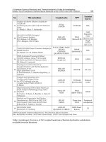
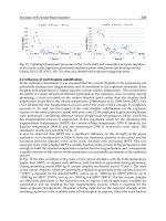
Table 10 shows the attribute comparison of 1K melamine crosslinked
clearcoats as compared to 2K isocyanate crosslinked clearcoats. Figure 12
graphically shows selected attributes from this comparison. Blocked isocyanate
clearcoats also exist, but these are not very common over plastic substrates
presumably due to the higher temperatures needed to cause the unblocking (95).
On the other hand, the use of low imino, methylated melamine resins (96) can
provide cure at temperatures as low as 82°C, opening up the opportunity for use
on heat-sensitive substrates.
6.3.3 Two Component
Two-component (2K) clearcoats have been considered the industry “gold stan-
dard” since their introduction on automotive plastic parts in the early 1990s.
T
ABLE
10 Clearcoat Technologies for Plastics Attribute Comparison
1K Melamine 2K isocyanate
Property flexible clear clear for plastics
Glass transition temperature, T
g
Low Higher
Initial appearance Good Excellent
% Flexibility
a
23°C >20 >20
−30°C 5 to 8 2 to 5
Scratch resistance, % gloss retention 90–95 70–85
Gouge resistance Good to very good Excellent
Impact resistance, −15°C
a
Excellent Good to excellent
Stain resistance Poor to good Very good to excellent
Jacksonville etch rating, 0 = best 10 to 12 5 to 7
Xenon weathering, % retention
2500 KJ 80 to 95 95 to 100
3500 KJ 65 to 85 80 to 95
% appearance retention, Florida
12 months 86–94 96+
24 Months 68–82 94+
36 Months 56–68 86+
48 Months 36–58 80+
a
Influenced by substrate flexural modulus.
194 Yaneff
F
IG
.12 Comparison of 1K melamine vs. 2K isocyanate clearcoats for film attributes.
Performance and Durability Testing 195
Their outstanding performance and durability, due to the urethane functional
isocyanate crosslinker, has been responsible for their widespread use, especially
on premium parts and vehicles. The isocyanate group has the advantage that it
can crosslink with moisture at low temperature. This can help oven-baked 2K
coatings continue to crosslink even after being removed from the oven. Accord-
ing to infrared data, many 2K systems only consume 60 to 70% of the available
isocyanate in the oven and require 10 to 14 days to develop full properties.
Isocyanates can also undergo a wide variety of primary reactions. For
example, they can react with alcohols to form urethanes and react with amines
to give ureas. Isocyanates can also undergo secondary reactions reacting with
urethanes and ureas to give allophanates and biurets, respectively. Isocyanates
can also release carbon dioxide that can appear as small bubbles or micropop-
ping in the clearcoat film. The use of moisture scavengers and other additives
can help reduce or completely eliminate these defects in baked systems.
For automotive applications, both low-bake (80 to 90°C) and high-bake
(120 to 130°C) 2K clearcoats are in use today. Most 2K coatings for plastics
use aliphatic hexamethylene diisocyanate (HDI) as its film properties exhibit a
good combination of flexibility and durability, and reasonably fast reactivity.
For some applications, blending in some isophorone diisocyanate (IPDI) or bi-
uret is used to increase surface hardness or produce softer, more flexible films.
The choice of catalyst, temperature, and alcohol can dramatically influence the
composition of the final product, especially when IPDI is used (97). There is
little use of aromatic diioscyanates such as toluene diisocyanate (TDI) or meth-
ane diphenyl diisocyanate (MDI) due to their high contribution of yellowing. In
general, the addition of a small amount of catalyst is enough to induce cure of
the high-bake coating at lower temperature. The strongest catalysts are materials
such as mercuric compounds, tin (IV) compounds, zinc (II) carboxylates, ter-
tiary amines, and carboxylic acids (98). In cases where the resin does not cure
fast enough, more reactive, faster curing materials can be used.
Two-component clearcoats are resistant to attack by acid and base and as
such can offer very good resistance to acid rain, chemicals, solvents, and road
contaminants such as tar, oil, and even asphalt. In cases where appearance and
durability requirements are demanding, 2K clearcoats can perform well. It is
quite normal to see 80 to 90% gloss retention after five years of Florida black-
box exposure with 2K coatings.
7 CONCLUSIONS AND FUTURE
It is evident that the OEM industry desires ten-year durable coatings. As the
OEMs continue to increase the test severity and increase the amount of testing
required to fully qualify new plastics and coatings, it will take considerably
196 Yaneff
longer to introduce these changes. The requirement of multiyear Florida expo-
sure panels highlights the need for a test protocol that will accurately predict
the long-term durability of a particular system in a relatively short time frame.
Moreover, any adopted technique must be accepted by all OEMs as being repre-
sentative of real-world exposure, or it will only be considered indicative and
not a true replacement for the long-term testing.
The coating of plastic parts will continue as long as the process remains
cost effective relative to other decorating options. To this end, some OEM
stylists have chosen to specify molded-in-color plastics, especially for sport
utility and lower-priced vehicles. The use of partially painted plastic parts is
also becoming more prevalent, but brings with it potential problems with de-
masking and adhesion. Alternate decoration processing methods will continue
to be explored in an attempt to eliminate a step and reduce cost. Fully paintable
conductive TPO may be the process of choice for the economical painting of
TPO bumpers. Topcoats adhering directly to TPO, without the use of any form
of adhesion pretreatment or adhesion promotor may appear in limited applica-
tions. The widespread use of this technology with the multitude of plastics
available on the market and colors available may turn into a logistical night-
mare.
Although not discussed in this chapter, changes in solvent composition
will shift to be more ecologically friendly. Conversion to fully compliant haz-
ardous air pollutant solvents (HAPS) will require complete reformulation of
most coating resins. Free solvent replacement to HAPS compliant can occur
immediately and substitution in all manufactured resins should be fully imple-
mented within the next few years. Greater use of waterborne materials (primers,
basecoats, and clears) is expected within the next five to ten years as long as
application properties, performance, and durability can be attained.
REFERENCES
1. PV Yaneff. Examining the Appearance and Durability of Painted Automotive Plas-
tics. Paint and Coatings Industry. Troy, MI: Business News Publishing, June 1998,
pp 60–74.
2. PE Pierce, CK Schoff. Coating Film Defects, Federation of Societies for Coatings
Technology, Monograph Series, Philadelphia, 1988, pp 14–17.
3. RHJ Blunk, JO Wilkes. Surface-tension-driven flows of coatings: Bondline readout
formation. J Coatings Technology 73(918):63–71, 2001.
4. JA Baglhdachi. Adhesion Aspects of Polymeric Coatings, Federation of Societies
for Coatings and Technology Monograph Series, Philadelphia, 1998, pp 7–23.
5. RA Ryntz. Adhesion to Plastics-Molding and Paintability. Global Press, USA,
1998, pp 95–101.
6. C Schoff. Wetting and wettability in the painting of plastics. Proceedings of the
Fourth International Coatings for Plastics Symposium, Troy, MI, 2001.
Performance and Durability Testing 197
7. J Cremers. DSM mechanical peel test. Conference Proceedings, TPOs in Automo-
tive, Novi, MI, 1997.
8. RA Ryntz, D Britz, DM Mihora, R Pierce. Measuring adhesion to poly(olefins):
The role of adhesion promoter and substrate. J Coatings Technology 73(921):107–
115, 2001.
9. R Ryntz, M Everson, G Pollano. Friction induced paint damage as affected by
clearcoat chemistry. Proceedings of Twenty-Fourth International Waterborne,
High-Solid, and Powder Coatings Symposium, New Orleans, 1997, pp 259–276.
10. EW Orr. Performance Enhancement in Coatings. Cincinnati: Hanser Publishers,
1998, pp 126–128.
11. RA Ryntz, AC Ramamurthy, DJ Mihora. Thermal and impact induced stress failure
in painted TPO: The role of surface morphology. J Coatings Technology 67(840):
35–46, 1995.
12. RA Ryntz, AC Ramamurthy, JW Holubka. Stone impact damage to painted plastic
substrates. J Coatings Technology 67(842):23–31, 1995.
13. ZW Wicks Jr., FN Jones, SP Pappas. Organic Coatings: Science and Technology.
New York: John Wiley and Sons, 1994, pp 112–118.
14. K Adamsons, RJ Barsotti, L Lin, BV Gregorovich, P McGonigal, B Neff, G Black-
burn, D Nordstrom, J Johnson. Scratch and mar testing: General issues and applica-
tion of the single nano-indenter micro-scratch technique in the study of newly pre-
pared and aged clearcoats. Conference Proceedings of Advanced Coatings
Technology, Detroit, 1997, pp 191–214.
15. W Shen, B Jiang, FN Jones. Measurement of mar resistance and study of the mar-
ring mechanism of polymeric coatings with scanning probe microscope. J Coatings
Technology 72(907):89–95, 2000.
16. JL Courter. Mar resistance of automotive coatings: I. Relationship to coating me-
chanical properties. J Coatings Technology 69(866):57–63, 1997.
17. FN Jones. Mar resistance of coatings. Proceedings of the First International Coat-
ings for Plastics Symposium, Troy, MI, 1998.
18. V Jardet, BN Lucas, W Oliver, AC Ramamurthy. Scratch durability of automotive
clear coatings: A qualitative, reliable and robust methodology. J Coatings Technol-
ogy 72(907):79–88, 2000.
19. BV Gregorovich, PJ McGonigal. Mechanical properties of coatings needed for
good scratch and mar. Proceedings of the Advanced Technology Conference, Mate-
rials Park, OH, 1992, pp 121–125.
20. RA Ryntz, GM Pollano. Scratch resistance of model coating systems. J Coatings
Technology 72(904):47–53, 2000.
21. PB Jacobs, T Engbert. Scratch and mar resistance of polyurethane automotive clear-
coats. Proceedings of the Advanced Coatings Technology Conference, Detroit,
1995, pp 29–39.
22. PV Yaneff, K Adamsons, RA Ryntz, D Britz. Structure property relationships in
flexible silane automotive coatings, Proceedings of Twenty-Eighth International
Waterborne, High-Solid, and Powder Coatings Symposium, New Orleans, 2001, pp
109–125.
23. K Adamsons, RJ Barsotti, L Lin, BV Gregorovich, P McGonigal, B Neff, G Black-
198 Yaneff
burn, D Nordstrom, J Johnson. Scratch and mar testing: General issues and applica-
tion of the single nano-indenter micro-scratch technique in the study of newly pre-
pared and aged clearcoats. Conference Proceedings of Advanced Coatings
Technology, Detroit, 1997, pp 191–214.
24. F Lee, B Pourdeyhimi, K Adamsons. Analysis of coatings appearance and surface
defects using digital image capture-processing-analysis system. In: D Bauer, J Mar-
tin, eds. Service Life Prediction of Organic Coatings. Washington: American
Chemical Society, 1999, pp 257–287.
25. Northwestern Society for Coatings Technology and Montreal Society for Coatings
Technology. A study of the effect of acid rain on alkyd, polyester, and silicone-
modified high-solids coatings. J Coatings Technology 67(850):19–28, 1995.
26. PJ Schmitz, JW Holubka, L Xu. Acid etch resistance of automotive clearcoats I.
Laboratory test method development. J Coatings Technology 72(901):77–82, 2000.
27. PJ Schmitz, JW Holubka, L Xu. Acid etch of automotive clearcoats II. Comparison
of degrading chemistry in laboratory and field testing. J Coatings Technology
72(902):53–61, 2000.
28. J McGee, B Bammel. Carbamate-based flexible coatings—a means to improve du-
rability of painted plastic automotive components. Conference Proceedings, TPOs
in Automotive, Novi, MI, 1998.
29. CK Schoff. Mechanical properties of automotive topcoats. Conference Proceedings,
Advanced Coatings Technology, Detroit, 1994, pp 61–78.
30. LW Hill. Mechanical Properties of Coatings. Federation of Societies for Coatings
Technology. Monograph Series, Philadelphia, 1987, pp 7–23.
31. LW Hill. Structure/property relationships of thermoset coatings. J Coatings Tech-
nology 64(808):29–42, 1992.
32. G Haake, JS Brinen, PJ Larkin. Depth profiling of acrylic/melamine formaldehyde
coatings. J Coatings Technology 67(843):29–34, 1995.
33. DY Perera. Role of stress on durability of organic coatings. In: RA Ryntz, ed.
Plastics and Coatings: Durability, Stabilization, Testing. Cincinnati: Hanser Gard-
ner, 2001, pp 115–119.
34. LW Hill. Overview of mechanical property changes during coating degradation. In:
DR Bauer, JW Martin, eds. Service Life Prediction of Organic Coatings: A Systems
Approach. ACS Symposium Series 722. New York: Oxford University Press, 1999,
pp 312–322.
35. ME Nichols, CA Darr. The effect of weathering on the stress distribution and me-
chanical performance of automotive paint systems. In: DR Bauer, JW Martin, eds.
Service Life Prediction of Organic Coatings: A Systems Approach. ACS Sympo-
sium Series 722. New York: Oxford University Press, 1999, pp 332–353.
36. ME Nichols, CA Darr. Effect of weathering on the stress distribution and mechani-
cal performance of automotive paint systems. J Coatings Technology 70(885):141–
149, 1998.
37. DY Perera, M Oosterbrook. Hygrothermal stress evolution during weathering in
organic coatings. J Coatings Technology 66(833):83–88, 1994.
38. DR Bauer, JW Martin. Service Life Prediction of Organic Coatings. ACS Sympo-
sium Series 722. New York: Oxford University Press, 1999.
Performance and Durability Testing 199
39. JW Martin, SC Saunders, FL Floyd, JP Wineburg. Methodologies for Predicting
the Service Lives of Coating Systems, Federation of Societies for Coatings Tech-
nology. Monograph Series, Philadelphia, 1996, pp 7–13.
40. EV Schmid. Exterior Durability of Organic Coatings. Surrey, England: FMJ Inter-
national Publications Limited, 1988, pp 2–15.
41. L Crawley. Predicting long-term durability of automotive coatings. Conference Pro-
ceedings of Advanced Coatings Technology, Detroit, 1993, pp 153–170.
42. ZW Wicks Jr., FN Jones, SP Pappas. Organic Coatings: Science and Technology,
Volume II. New York: John Wiley and Sons, 1994, pp 145–148.
43. KM Wernstahl, B Carlsson. Durability assessment of automotive coatings—design
and evaluation of accelerated tests. J Coatings Technology 69(885):69–75, 1997.
44. G Pilcher, G Van de Streek, J Chess, D Cocuzzi. Accelerated weathering: Science,
pseudo-science or superstitution? Proceedings from the Research Conference on the
Science and Technology of Organic Coatings, Hilton Head, SC, 1998, pp 199–212.
45. G Pilcher, G Van de Streek, J Chess, D Cocuzzi. Accelerated weathering: Science,
pseudo-science or superstitution? In: Service Life Prediction of Organic Coatings.
ACS Symposium Series 722. New York: Oxford University Press, 1999, pp 130–
148.
46. CJ Sullivan, CF Cooper. Polyester weatherability: Coupling frontier molecular or-
bital calculations of oxidative stability with accelerated testing. J Coatings Technol-
ogy 67(847):53–62, 1995.
47. ASTM J1960.
48. D Bauer, J Peck, R Carter III. Evaluation of accelerated weathering tests for a
polyester-urethane coating using photoacoustic infrared spectroscopy. J Coatings
Technology 59:103–107, 1987.
49. SR Smith. Accelerated weathering vs. Florida weathering for automotive coatings
on plastics. Proceedings of the Second International Coatings for Plastics Sympo-
sium, Troy, MI, 1999.
50. JL Gerlock, CA Smith, VA Cooper, SA Kaberline, TJ Prater, RO Carter III, AV
Kucherov, T Misovski, and ME Nichols. A brief review of paint weathering re-
search at Ford. In: Service Life Prediction Methodology and Metrology. ACS Sym-
posium Series 805, Washington, 2002.
51. DR Bauer. Predicting in-service weatherability of automotive coatings: A new ap-
proach. J Coatings Technology 69(864):85–96, 1997.
52. DR Bauer. Chemical criteria for durable automotive topcoats. J Coatings Technol-
ogy 66(835):57–65, 1994.
53. JL Gerlock, W Tang, MA Dearth, TJ Korniski. Reaction of benzotriazole ultraviolet
light absorbers with free radicals. Polymer Degradation and Stability 48:121–130,
1995.
54. JL Gerlock, TJ Prater, SL Kaberline, JE deVries. Assessment of photooxidation
in multi-layer coating systems by time-of-flight secondary ion mass spectroscopy.
Polymer Degradation and Stability 47:405–411, 1995.
55. MA Dearth, TJ Korniski, JL Gerlock. The LC/MS/MS characterization of photoly-
sis products of benzotriazole-based ultraviolet absorbers. Polymer Degradation and
Stability 48:111–120, 1995.
200 Yaneff
56. JL Gerlock, RO Carter, M Agarwal. Photoacoustic FTIR and UV spectroscopic
analysis of clearcoat photooxidation and UVA disposition in Florida test panels.
Technical Report No. SR-95-041 Ford Motor Company, 1995.
57. GL Gerlock, AV Kucherov, ME Nichols. On the combined use of UVA, HALS,
photooxidation, and fracture energy measurements to anticipate the long-term
weathering performance of clearcoat/basecoat automotive paint systems. J Coatings
Technology 73(918):45–54, 2001.
58. S Babinec, R Lewis, B Cieslinski. Conductively modified TPO for enhanced elec-
trostatic painting. Proceedings of the Fourth International Coatings for Plastics
Symposium, Troy, MI, 2001.
59. S Vessot, J Andrieu, P Laurent, J Galy, JF Gerard. Air convective drying and
curing of polyurethane-based paints on sheet molding compound surfaces. J Coat-
ings Technology 70(882):67–76, 1998.
60. G Faoro. Potential reasons for yellowing of coatings over plastic substrates. Proceed-
ings of the Fourth International Coatings for Plastics Symposium, Troy, MI, 2001.
61. E Nunez. Surface energy measurements on thermoplastic olefins. Conference Pro-
ceedings of Advanced Coatings Technology, Detroit, MI, 1993, pp 91–97.
62. R Ryntz, D Britz, D Minhora, R Pierce. Measuring adhesion to poly(olefins): The
role of adhesion promoter and substrate. J Coatings Technology 73(921):107–115,
2001.
63. D Kondos, M Mayo. Quantitative adhesion testing of reactor and compounded
TPOs II. Proceedings of the Fourth International Coatings for Plastics Symposium,
Troy, MI, 2001.
64. J Lawniczak, R Clemens, G Batts, K Middleton, C Sass. How do chlorinated polyo-
lefins promote adhesion of coatings to polypropylene? Conference Proceedings of
Advanced Coatings Technology, Detroit, 1993, pp 205–217.
65. J Lawniczak, C Sass, R Evans. Effects of formulation variables on the performance
of CPO-based adhesion promoters on polypropylene substrates. Conference Pro-
ceedings of Advanced Coatings Technology, Detroit, 1994, pp 305–315.
66. JE Lawniczak, PJ Greene, R Evans, C Sass. Water-reducible adhesion promoters
for coatings on polypropylene-based substrates. J Coatings Technology 65(827):
21–26, 1993.
67. M Jackson, F Stubbs, J Mecozzi, D Miklos. Chlorine-free, zero VOC, thermoset,
waterborne adhesion promoter for thermoplastic polyolefins (TPOs). Conference
Proceedings of Advanced Coatings Technology, Detroit, 1997, pp 95–105.
68. TJ Prater, SL Kaberline, JW Holubka, RA Ryntz. Examination of the distribution of
a TPO adhesion promoter material in a painted TPO system. J Coatings Technology
68(857):83–91, 1996.
69. DJ St. Clair. Coating resins based on melamine cured polyolefin diol. Conference
Proceedings, TPOs in Automotive, Novi, MI, 1996.
70. AA Eloursi, DP Garner. Electrostatic painting of plastics I: Electrical properties of
plastics and primers. J Coatings Technology 63(803):33–37, 1991.
71. AA Eloursi, DP Garner. Electrostatic painting of plastics II: Electric field effects.
J Coatings Technology 64(805):39–44, 1992.
72. A Calahorra, D Aharoni, H Dodiuk. Carbon filled paints of improved electrical
conductivity. J Coatings Technology 64(814):33–37, 1992.
Performance and Durability Testing 201
73. KS Katti, MW Urban. Effect of carbon black on adhesion to plastics in solvent-
borne 2K polyurethanes. J Coatings Technology 72(903):63–70, 2000.
74. LP Haack, JW Holubka. Bake oven induced variation of surface chemistry on elec-
trocoat paint: Effect on primer-electrocoat intercoat adhesion. J Coatings Technol-
ogy 72(903):35–44, 2000.
75. FY Hunt, MA Galler, JW Martin. Microstructure of weathered paint and its relation
to gloss loss: Computer simulation and modeling. J Coatings Technology 70(880):
45–54, 1998.
76. S Grace, J Petzoldt. Coating automotive plastics with 2K waterborne polyurethane
coatings. Conference Proceedings of Advanced Coatings Technology, Detroit, MI,
1997, pp 72–78.
77. C Hegedus, D Lawson, D Lindenmuth. Two component, waterborne polyurethane
coatings: chemistry and application. Proceedings of Twenty-fifth International Wa-
terborne, High-Solid, and Powder Coatings Symposium, New Orleans, 1998, pp
391–408.
78. RL Gray, RE Lee. UV stabilization of polypropylene and TPOs in automotive
applications. Conference Proceedings, TPOs in Automotive, Novi, MI, 1996.
79. JE Picket. Photostabilization of plastics by additives and coatings. In: RA Ryntz,
ed. Plastics and Coatings: Durability, Stabilization, Testing. Cincinnati: Hanser
Gardner, 2001, pp 73–86.
80. A Valet. Light Stabilizers for Paints. Hannover, Germany: Vincentz Verlag, 1997,
pp 46–72.
81. DR Bauer. Stabilization of coatings. In: RA Ryntz, ed. Plastics and Coatings: Dura-
bility, Stabilization, Testing. Cincinnati: Hanser Gardner, 2001, pp 107–113.
82. G Haake, E Longordo, J Brinen, F Andrews, B Campbell. Chemisorption and phys-
ical adsorption of light stabilizers on pigment and ultrafine particles in coatings. J
Coatings Technology 71(888):87–94, 1999.
83. RD Tokash. Ultraviolet light absorbers: A study of migration susceptibility from
flexible topcoats into TPO substrates. Conference Proceedings of Advanced Coat-
ings Technology, Detroit, MI, 1993, pp 173–183.
84. G Haacke, FF Andrews, BH Campbell. Migration of light stabilizers in acrylic/
melamine clearcoats. J Coatings Technology 68(855):57–62, 1996.
85. N Cliff. Reactable light stabilizers for use over plastic substrates. Proceedings of
the Fourth International Coatings for Plastics Symposium, Troy, MI, 2001.
86. N Albrecht. Proceedings of the International Coatings Technology Conference,
Chicago, 1996.
87. PE Ferrell, JJ Gummeson, LW Hill, LJ Truesdell-Snider. The reaction of amines
with melamine formaldehyde crosslinkers in thermoset coatings. J Coatings Tech-
nology 67(851):63–69, 1995.
88. S Haseebuddin, KVSN Raju, M Yaseen. Crosslink density and cure window of
oligourethane diol/melamine high-solids coatings. J Coatings Technology 70(879):
35–42, 1998.
89. PJ Schmitz, JW Holubka, L Xu. Mechanism for environmental etch of acrylic mela-
mine-based clearcoats: Identification of degradation products. J Coatings Technol-
ogy 72(904):39–45, 2000.
90. P Lamers, K Johmson, W Tyger. Ultraviolet irradiation of melamine containing
202 Yaneff
clearcoats for improved acid etch performance. Conference Proceedings of Ad-
vanced Coatings Technology, Detroit, MI, 1993, pp 125–152.
91. M Green. Low VOC carbamate functional coatings compositions for automotive
topcoats. Proceedings of Twenty-Seventh International Waterborne, High-Solid,
and Powder Coatings Symposium, New Orleans, 2000, pp 224–239.
92. ML Green. Low VOC carbamate functional coatings compositions for automotive
topcoats. J Coatings Technology 73(918):55–62, 2001.
93. PV Yaneff, K Adamsons, RA Ryntz, D Britz. Structure property relationships
in flexible silane automotive coatings. J Coatings Technology, 74(933): 135–141,
2002.
94. MJ Chen, FD Osterholtz, EP Pohl, PE Ramdatt, A Chaves, V Bennett. Silanes in
high-solids and waterborne coatings. J Coatings Technology 69(870):43–51, 1997.
95. Z He, WJ Blank. Crosslinking with malonate blocked isocyanates and with mela-
mine resins. J Coatings Technology 71(889):85–90, 1999.
96. LW Hill, S Lee. Effect of melamine-formaldehyde structure on cure response of
thermoset coatings. J Coatings Technology 71(897):127–133, 1999.
97. R Lomolder, F Plogmann, P Speier. Selectivity of isophorone diisocyanate in the
urethane reaction. Influence of temperature, catalysis and reaction partners. J Coat-
ings Technology 69(868):51–57, 1997.
98. T Potter. Chemistry and technology of polyurethane coatings. Proceedings of the
1996 FSCT International Coatings Technology Conference: Polymer Chemistry for
the Coatings Formulator, Chicago, 1996.
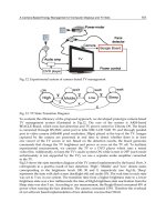
6
Painting Problems
Clifford K. Schoff
Schoff Associates, Allison Park, Pennsylvania, U.S.A.
1 INTRODUCTION
Most readers of this chapter will know that painting any surface well is not an
easy task and that painting plastics is even more difficult. One reason for the
occurrence of problems is that there are so many different plastics. Some are
hard, others are soft; many have surfaces of low polarity, others have highly
polar surfaces; some dissolve or craze on contact with solvents, others are com-
pletely insensitive to solvents. Compared to pretreated metals, plastics generally
have lower surface energies; are smoother and less porous (and if they are po-
rous, that causes problems); and are less polar. Plastics tend to be more difficult
to wet and adhere to than pretreated metals, particularly where mold release
agents or components that migrate to the surface are involved. Coated plastic
parts often are required to match other parts on an assembly or vehicle for color
and texture. Customers have become more demanding so that appearance that
was acceptable a few years ago is considered to be a problem now. There is no
question that plastics can be painted and painted very well, but it is important
to be aware of the difficulties that can occur and to know what to do about
them. This chapter provides information on a number of surface defects and
other problems encountered when painting plastics. More information on coat-
ings defects in general is given in Refs. 1–5.
The appearance and durability of a coated plastic are dependent on the
entire painting process as well as the properties of the paint and plastic. Before
discussing the individual defects and problems, a brief discussion of the various
steps in painting plastics is in order.
203
204 Schoff
2 PAINTING PROCESS
2.1 Cleaning
It is important for any surface to be clean before it is painted. Dirt hurts appear-
ance and affects paintability. Dirty surfaces are difficult to wet and may give
adhesion problems or surface defects even if initial wetting seems adequate.
Dirt leads to rework and recycling. Most plant cleaning processes work well,
but their effectiveness is not always monitored adequately. It is important to
audit the cleaning process periodically to determine whether the parts really are
clean. I have followed parts through a line and noted that much of the sanding
dust that was on the surface before a power wash was still there afterward. It
may be necessary to wipe parts with tack cloths before they are washed. If so,
then the lighting and operator positioning must be such that the dirt can be
readily seen and removed. Even if parts are clean, they may be soiled by racks
that are dirty, especially where the dirt on the racks is loose. Racks must be
kept clean as well. In fact, the entire line must be kept clean so that clean parts
do not become soiled in tunnels, booths, and ovens.
Many plastic parts have mold release agents on their surfaces and plasti-
cizers and other components or additives may come to the surface over time.
These surface contaminants must be removed. Sometimes parts are cleaned then
stored, which usually means that they need to be cleaned again before they are
painted. This is done to remove dirt picked up in storage and any material that
migrated to the surface. The cleaning process can cause difficulties. Detergent
residues can result in water spotting and other appearance problems. Good rins-
ing is very important, otherwise one kind of dirt is traded for another.
2.2 Application
Plastics can be painted using a number of application techniques, including con-
ventional air spray, airless, electrostatic spray (gun or bell), flow coat, or even
dip coating. Conventional spray probably is the most common method. Some
lines use both guns and bells. Under the right conditions, the results of paint
application can be a smooth coating with no defects. Unfortunately, there are a
lot of things that can go wrong. Application can affect appearance in a number
of ways ranging from color to smoothness to aluminum flake orientation in
metallics. Often these problems are blamed on the paint, but many of them can
be solved by adjusting atomization pressures and flow rates and optimizing the
ratio between the two.
Application equipment can produce spits, drops, and overspray, all of
which can give defects that look much like dirt. Worn or damaged guns and
bells are particularly bad for causing bubbles and spits. I have seen worn and
nicked bells in a number of facilities where plastics were being painted. Applica-
Painting Problems 205
tion equipment must be kept clean and examined often for wear and damage.
Worn or damaged parts must be replaced. Although expensive, it is very useful
to have two sets of equipment, one for operation, the other for cleaning and
preventive maintenance.
2.3 Flash and Cure
In order to achieve necessary properties, coatings must lose their solvents and
be crosslinked (cured). The beginning of the flash period is one of great vulnera-
bility for wet coatings. The viscosity is low, contaminants can cause craters, dirt
is easy to pick up, etc. The coating becomes more resistant as the flash period
continues, then experiences a new period of vulnerability as the coated part
enters the oven. The viscosity drops sharply and new contaminants may be
encountered.
Cure can be accomplished in a variety of ways. With most paints, cross-
linking reactions occur on baking and/or there are two parts that react on mixing.
Some paints for plastics are cured by UV radiation. Poorly controlled curing
can cause defects, hurt appearance, and severely compromise end-use properties
such as scratch and impact resistance. Overcure or undercure can be due to the
paint formulation, but that is almost always detected in the lab and the formula
is modified until the problem is solved. Mistakes in the manufacture of the paint
also can lead to cure problems as can oven temperatures that are too high or too
low. Additives in the plastic such as amines may interfere with cure. Degree of
cure can be determined in the laboratory by the relatively crude solvent rub
technique or analysis of solvent extractables. Thermal analysis (6–9) and dielec-
tric analysis methods (10–13) can be used to follow the cure process or deter-
mine the degree of cure. Options for testing cure on line (or immediately off
line) are very limited and I am under the impression that it is rarely measured.
If parts seem soft or tacky, more testing may be done. Painted auto parts occa-
sionally are soaked in fuel to evaluate resistance that is a function of cure.
3 SURFACE DEFECTS
A number of defects can occur on the surface of the coating during or soon after
application and/or during cure. These defects are unacceptable because they
spoil the appearance of the part or object and may contribute to durability prob-
lems. Because of them, many parts must be discarded, recycled, or sanded and
repainted. If at all possible, these defects must be prevented, but before we
prevent them we must understand why they occur.
3.1 Surface Tension–Driven Defects
A number of surface defects are caused by or affected by surface tension. How-
ever, surface tension is not only a troublemaker. It is the driving force for level-
206 Schoff
ing and, therefore, is responsible for smooth coatings with good appearance as
well as for defects. Several different defects are discussed in the following text.
The reader should refer to Refs. 1–5 and 14–17 for additional details on surface
flows and surface tension–related defects.
3.1.1 Craters
Other than dirt, craters probably are the most common type of surface defect.
They also are the most frustrating and irritating defect to deal with as well as
being the most difficult problem to solve. Craters are small bowl-shaped depres-
sions that appear in a coating. They occur where there is a low surface-tension
contaminant in the paint, that falls on it, or is on the substrate. The paint flows
or is pushed away from the low surface-tension area, leaving a circular defect
as shown in Figure 1. Many, but not all craters have raised rims as shown in
the figure. Craters form very rapidly, usually during or immediately after appli-
cation of the paint. With baked coatings, they also can occur in the oven.
One of the difficulties with craters is that there are so many possible
causes. These include hydrocarbon and fluorocarbon oils and lubricants, sili-
cones, plasticizers, resin gel particles, oven condensate, dirt, fibers, filter mate-
F
IG
.1 An example of a crater in a metallic topcoat.
Painting Problems 207
rial, overspray, antiperspirants and other personal care products, poorly dis-
solved or dispersed additives (especially silicones), contaminated raw materials,
and contaminated drums, totes, or other containers. To make matters worse,
when the defect is examined after the coating is cured, analysis rarely identifies
the material that caused the crater. Whatever it was, it evaporated in the oven
or dissolved back into the paint. Even very powerful analytical instruments usu-
ally see nothing but paint in the crater. The combination of many possible causes
and the difficulty of identifying the contaminant means that root cause analysis
of craters is very difficult and often fails. Many crater problems go away without
the cause having been determined. However, careful detective work when cra-
ters do occur, coupled with good housekeeping and flow control all the time,
usually can keep craters at a low level.
3.1.2 Dewetting (Crawling)
This defect involves the pulling away of a paint film from an edge, hole, or low
surface-tension contaminant or surface. An example of dewetting is shown in
Figure 2. Pulling away from a low surface-tension region is similar to crater
formation, but dewetting from edges needs more explanation. Surface tension
F
IG
.2 Dewetting of a topcoat over an undercoat.
208 Schoff
always tries to minimize surface area. At edges, this manifests itself as flow to
make a smooth cross-sectional curve and a thin coating at the edge as shown in
Figure 3. Additional flow away from edges occurs on baking if the edge heats
up faster, which causes the surface tension to drop in that area and gives a
surface-tension gradient. Another aspect is that once flow begins, it may con-
tinue well beyond where it is expected to stop. For example, you can force wet
a low surface-tension Teflon or polypropylene sheet by spraying it with paint.
This usually will produce a continuous film, but if this wet film is stressed by
running a stick along it, many paints will roll back a considerable distance, far
beyond the original groove.
3.1.3 Telegraphing
This defect involves the reproduction of surface features on a substrate by a
coating applied to that substrate. Instead of hiding surface irregularities such as
a rough surface, sand scratches, fingerprints, solvent wipe marks, detergent resi-
dues, etc., the coating makes them more obvious. Figure 4 shows telegraphing
of a fingerprint. Telegraphing in light metallic basecoats can give dark or light
streaks over sanded areas (often called sand mars) or wipe marks on primers.
Telegraphing is not completely understood, but it involves surface tension–
driven flow and the driving force appears to come from low surface-tension
residues or from sharp edges or both. Wetting and flow on completely sanded
F
IG
.3 Diagram showing a thin edge and poor edge coverage along the vertical
and a fat edge or picture framing on the horizontal. (From Ref. 4, used with permis-
sion.)
Painting Problems 209
F
IG
.4 Telegraphing of a fingerprint. Instead of hiding the fingerprint, the paint
has made it much more obvious.
areas are affected by the roughness, porosity, and increased wettability of the
abraded surface.
Fiber read-through in sheet molding compound (SMC) and other fiber-
filled composites can be considered as a special case of telegraphing. The glass
fibers in the composite are amplified instead of being hidden. This may be due
to the fibers being too close to the surface, but usually occurs when solvents in
the paints penetrate the composite and swell the surface area producing an effect
similar to grain raising in wood. Factors that affect fiber read-through include
the quality of the substrate, the solvents used in the paints, effectiveness of the
primer in acting as a barrier, and the bake temperatures used for the primer and
the paints applied over it.
3.1.4 Bondline Readout
This defect appears over plastic parts with reinforcements (18). The bonded
backing acts as a heat sink and the heat-up and cool-down behavior of backed
and unbacked areas are different. This results in a temperature difference be-
tween reinforced and nonreinforced areas that may be as large as 30°C (50°F)
210 Schoff
during the bake, although it usually is much smaller. Even a small difference
may produce a significant temperature gradient if it occurs over a short distance.
This defect can occur even before the oven, probably due to different degrees
of cooling by solvent evaporation during the flash. Temperature gradients cause
surface-tension gradients (higher temperature means lower surface tension) that
in turn cause flow. Noticeable steps or ridges in surfaces of clears and color
differences in pigmented coatings may occur because of this flow. The effect
can be very striking on large parts such as automobile hoods and decklids where
every rib of the underlying reinforcement can be seen on the surface. Color
effects may be due to differences in film thickness in adjacent areas or, in
coatings containing aluminum flakes, due to flake orientation differences. For
example, light metallics give a dark smudge along the bondline when bondline
readout occurs.
Bondline effects have been seen immediately on application (when any
evaporative cooling was just beginning). It is not known whether this was due
to different temperatures across the part (e.g., from the primer bake) or because
of electrostatic effects. Bondline readout is greatly affected by the application
process (type of gun or bell, number of passes), flash time (longer flash reduces
the effect), the thickness of the primer, the design of the part, and the tempera-
ture of the oven. Bondline effects that occur on application have been known to
diminish or disappear with higher bake temperatures.
3.1.5 Picture Framing (Fat Edge)
This defect consists of a bead or thick border along or near the edge of a part
as shown in Figure 5 and diagrammed in the upper part of Figure 3. This defect
is less common on painted plastic than on metal, probably because plastic parts
tend to have more curvature and fewer sharp edges than do metal parts. Fat
edge can be due to electrostatic spray wrap over conductive primers as well as
to surface-tension effects on application or in the oven. It is possible that once
a bead begins to build, convection flow (see the following text) will cause it to
grow even larger. The bead may be right at the edge or a short distance back
from it. Evaporative cooling at the edge on application can cause flow toward
the edge. If the edge heats up more rapidly than the bulk of the part, there will
be a low surface-tension region along the edge and paint will flow away from
the edge. However, as the solvent in that hotter area is driven off, the surface
tension at the edge will increase and flow will go toward the edge again. Even
if the bead is not obvious, the extra thickness may lead to popping.
3.1.6 Convection Flow Defects
It is difficult to know where to place these complex defects that include Be
´
nard
cells, flooding and floating, and probably many unexpected roughness and tex-
ture effects. They are caused by convection cells with flow beginning near the
Painting Problems 211
F
IG
.5 Picture framing or fat edge along the edge of a slot in a part.
coating-substrate interface, rising up to the surface, then dropping back down
as shown in Figure 6. This flow is driven by surface tension, but also is affected
by density effects. The defects are made worse by low viscosity, rapid solvent
evaporation, and pigment flocculation. They are very noticeable when they oc-
cur in a coating with a mix of colored pigments (especially where aluminum
pigments are involved—see Figure 7). They also occur in whites where they
can lower gloss and in clears where they affect smoothness. Convection cells in
a topcoat can cause a scouring action on the coating underneath and this proba-
bly is responsible for some of the interactions between bases and clears that
hurt appearance.
3.2 Wetting and Wettability
This is a good place to stop and discuss the process by which a liquid interacts
with a solid. This process is called wetting. From the standpoint of painting, it
involves bringing the liquid paint into contact with the substrate, displacing air
and moisture, and adsorbing the paint onto the surface. Wettability is the ability
of a substrate to be wet by a particular liquid. Wettability usually is described
in terms of a sessile or resting drop (see Fig. 8). The contact angle (θ) between
212 Schoff
F
IG
.6 Diagram of convection flow. (From Ref. 4, used with permission.)
F
IG
.7 Blue metallic elastomeric coating: upper part—Be
´
nard cells formed by con-
vection cells; lower part—flooding and floating of aluminum flake pigment.
Painting Problems 213
F
IG
.8 Diagram of a sessile (resting) drop on a substrate. The angle θ is called
the contact angle and is a measure of the wettability (ease of wetting) of the
substrate. (From Ref. 5, used with permission.)
the drop and the surface is a measure of wettability. A drop that spreads and
forms a low contact angle with the substrate is said to wet well. We also say
that the surface is highly wettable by that liquid. There is an intermediate situa-
tion where the drop gives a low-to-moderate contact angle (20–50°). We tend
to call that wetting also, but it definitely is different. This intermediate state is
quite common with paints and typical substrates, including many plastics.
Wettability is determined by who wins the competition between paint-
substrate adhesive forces and cohesive forces in the paint (19). Adhesive forces
cause the paint to spread. Cohesive forces cause the drop to bead up. The contact
angle is determined by the balance between the two forces. Wetting occurs when
the liquid paint “likes” the substrate, that is, is compatible with it, and beading
occurs when the paint does not “like” the substrate. Surface contamination, sand-
ing, cleaning, and other processes can can change this compatibility, thereby
changing the wettability.
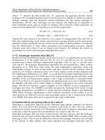
3.3 Volatile-Related Defects
Surface tension–driven defects certainly are not the only ones that occur on
paint lines. Paints contain volatile solvents that evaporate during the flash and
bake. Other gases such as air may be incorporated into the paint during stirring,
pumping, or spraying. In addition, volatile materials may come from cure reac-
tions or the plastic substrate. Volatiles can be trapped as a coating dries and
cures resulting in pinholes, bubbles, or crater-like blowouts. Solvent pops (Fig.
9) occur when solvent is trapped as the film forms and blows out rather than
diffusing through the film.
The production of volatiles from a substrate often is called gassing, but
with SMC plastics, it is termed porosity blowout. The defect usually looks like
a crater or solvent pop, but careful examination with a microscope often shows
a small hole that goes down into the substrate (Fig. 10) A cross section looks
like the diagram in Figure 11. The culprit usually is water vapor trapped in