Coatings of Polymers and Plastics Part 8 potx
Bạn đang xem bản rút gọn của tài liệu. Xem và tải ngay bản đầy đủ của tài liệu tại đây (325.1 KB, 25 trang )
164 Yaneff
Simple adhesion testing can be done by applying some sort of scribe into
the painted part followed by applying a piece of tape, rubbing it to ensure good
adhesion, and then rapidly lifting the tape in an upward motion. An example of
this type of adhesion testing is ASTM D 3359. While many adhesion test varia-
tions exist (cut patterns, types of tape, pull rates), they all can quantify the
amount of paint delamination numerically or relative to a standard. Low surface-
tension agents in the coating can artificially reduce the adhesive strength of the
tape to the coating and thus give false readings. Removing the surfactant from
the surface through solvent wiping can ensure more meaningful and representa-
tive results. Multiple paints passing the tape adhesion test does not necessarily
differentiate between adhesive strengths and more sophisticated testing can be
useful. Peel strength testing can be performed on painted plastics using a tensile
tester (7). This destructive test procedure can give the energy necessary for paint
removal and allows the comparison of one paint to another. More recently, an
in situ adhesion test, described as compressive shear delamination (CSD), has
been reported to quantify the adhesive/cohesive strength of coatings to a variety
of TPO substrates (8) that eliminates the artificial film between the paint and
the adhesion promoter.
Not only is adhesive testing carried out under dry conditions but also
under wet conditions. Exposing the painted part to a humidity chamber (typi-
cally 100% relative humidity at 38°C) for 96 to 240 hours can increase the
likelihood of paint delamination as moisture can penetrate through the coating
layer into the substrate. Increasing the temperature to 140 or 160°Casinthe
Cleveland Humidity Chamber can further test the adhesive properties of the
painted part. With the formulator performing testing under conditions that are
much more severe than specified by the OEM, it is likely to increase the chance
of success at the customer, even under conditions that are usually less than ideal.
In an attempt to upgrade the adhesive strength to TPO, more demanding
adhesion tests have been introduced. These include thermal shock, water jet,
and the gasoline soak. The latter will be covered in Section 2.3. In the thermal
shock test, a coated panel is stored at cold temperature for a minimum of four
hours after being scribed with an X. High-pressure steam is then bombarded at
the center of the X for 30 seconds. Any paint loss, whether it was adhesive or
cohesive within the TPO, is recorded.
Coatings have been observed to fail in this test on TPO, usually through
cohesive delamination within the TPO. The results improve significantly if the
TPO has seen a bake temperature of at least 121°C. Explanations have been
proposed suggesting that a morphological change within the TPO is necessary
allowing the rubber to move closer to the surface for greater penetration. Data
have shown that this 121°C thermal exposure dramatically improves thermal
shock testing and is necessary for paint systems to consistently pass this test.
The OEMs that use low-bake paint systems that do not reach this needed tem-
Performance and Durability Testing 165
perature do not consistently pass this test, but still give acceptable field perfor-
mance without any significant warranty issues. The water-jet test closer emu-
lates what happens in a do-it-yourself car wash, especially in the winter. In this
test, the cold painted part is scribed with a 10 × 10 line grid and then bombarded
with high-pressure water for 30 seconds. Unlike the thermal shock test, any
paint removal is usually adhesive loss. While some OEMs allow up to 20%
removal, in reality, any paint loss gives reason for concern. The use of stronger
adhesion promoters and tougher topcoats are generally enough to give excellent
water-jet performance on today’s TPO plastics. Including an additional process-
ing step such as flame treatment ensures successful thermal shock and water-jet
performance for low-bake systems as compared to high-bake systems (Table 2).
2.3 Gasoline Resistance
Gasoline-resistance testing has been included in case any fuel is spilled on the
plastic part. Early test methods were introduced to indicate acceptable cure.
When the gasoline dip test was initially introduced, 25 to 50 solvent dip cycles
were required in a hydrocarbon mixture blend of synthetic gasoline to pass.
More recently, the test was upgraded to include a scribe (as done for the adhe-
sion test) and then the panel soaked in the solvent blend for up to one hour.
Many of the available chlorinated polyalpha olefins (CPOs) would not meet
these upgraded requirements and new materials were needed. With the introduc-
tion of gasoline-alcohol blends (gasohol), some OEMs added 10 to 15% ethanol
to the gasoline blend. This increased even further the need for CPOs with
stronger gasohol resistance as the alcohol quickly weakened the plastic-to-adhe-
sion-promoter interface. Strengthening the paint layering system above the adhe-
sion promoter can also improve the results of this test. Performing some type
of adhesion test after removing the panel from the test solution can provide an
added level of comfort as this is much more severe than required by the OEM.
2.4 Gouging
Substrate gouging has been prevalent with automotive TPO bumpers and to the
naked eye it looks like a simple paint delamination issue. However, this failure is
localized within the substrate. This gouging or friction induced paint damage is
commonly seen with TPO substrates and can be reduced through judicious selec-
tion of paint clearcoat chemistry, optimizing the paint formulation and through the
use of silicone additives (9). The use of high levels of silicone can interfere with
the next coating layer and migrate upward when recoated (10) affecting color and/
or recoat adhesion. Therefore, silicone additives must be thoroughly studied prior
to addition, especially if other paint suppliers are used on the same paint line.
In the gouging process, a painted plastic part is hit by or hits a foreign
object (often another painted part). Failure occurs cohesively within the sub-
166 Yaneff
T
ABLE
2 Thermal Shock and Water Jet Results for Low-Bake (82°C)
and Comparison with High-Bake (121°C) Paint Systems
Thermal Water
Pretreatment AP Technology Color Bake shock jet
None Waterborne 1K/1K 25 at 121°C Pass Pass
None Solventborne 1K/1K 25 at 121°C Pass Pass
Flame None 1K/1K Black 25 at 121°C Pass Pass
Flame Waterborne 1K/1K 25 at 121°C Pass Pass
Flame Solventborne 1K/1K 25 at 121°C Pass Pass
None Waterborne 1K/1K 25 at 121°C Pass Pass
None Solventborne 1K/1K 25 at 121°C Pass Pass
Flame None 1K/1K White 25 at 121°C Pass Pass
Flame Waterborne 1K/1K 25 at 121°C Pass Pass
Flame Solventborne 1K/1K 25 at 121°C Pass Pass
None Waterborne 1K/1K 25 at 121°C Pass Pass
None Solventborne 1K/1K 25 at 121°C Pass Pass
Flame None 1K/1K Blue 25 at 121°C Pass Pass
metallic
Flame Waterborne 1K/1K 25 at 121°C Pass Pass
Flame Solventborne 1K/1K 25 at 121°C Pass Pass
None Waterborne 1K/2K 25 at 82°C 25.25 mm 405 mm
2
None Solventborne 1K/2K 25 at 82°C 18.43 mm Pass
Flame None 1K/2K Black 25 at 82°C Pass Pass
Flame Waterborne 1K/2K 25 at 82°C Pass Pass
Flame Solventborne 1K/2K 25 at 82°C Pass Pass
None Waterborne 1K/2K 25 at 82°C 22.72 mm 252 mm
2
None Solventborne 1K/2K 25 at 82°C 6.05 mm 99 mm
2
Flame None 1K/2K White 25 at 82°C Pass Pass
Flame Waterborne 1K/2K 25 at 82°C Pass Pass
Flame Solventborne 1K/2K 25 at 82°C Pass Pass
None Waterborne 1K/2K 25 at 82°C 9.33 mm 603 mm
2
None Solventborne 1K/2K 25 at 82°C Pass 81 mm
2
Flame None 1K/2K Blue 25 at 82°C Pass Pass
metallic
Flame Waterborne 1K/2K 25 at 82°C Pass Pass
Flame Solventborne 1K/2K 25 at 82°C Pass Pass
strate and results in the removal of the paint and a thin layer of substrate and
often appears like paint delamination. Because many automotive bumpers ex-
hibit this type of damage, a new gouge test requirement using an apparatus
called Slido has been developed and incorporated into some OEM specifications
for TPO substrates. Figure 3 shows typical Slido measurement equipment.
Performance and Durability Testing 167
F
IG
.3 Slido equipment for gouge measurement.
168 Yaneff
2.5 Chipping
The ability of a painted plastic part to withstand the impact of foreign objects
such as small stones and gravel has been extensively reviewed by Ryntz et al.
(11,12). Test methods range from the simple projectile of small stones at cold
substrate (e.g., SAE J400) to the more precise impact tests described by Ryntz
and others. In a fully painted plastic bumper, chip damage can occur:
1. Within the clearcoat
2. At the basecoat/clearcoat interface
3. Within the basecoat
4. Within the primer or adhesion promoter
5. At the paint-to-plastic interface
6. Within the plastic
The flexural properties of the substrate and the paint system used, the
adhesive strength of the paint layers, and the cohesive integrity of the substrate
and paint layers all can influence the location and severity of any chip damage
seen.
In general, flexible substrates (i.e., flexural modulus less than 700 MPa)
damage very little, if at all, upon impact. However, with the current industrial
trend toward higher modulus materials of 1200 to 1600 MPa, more damage will
result. In fact, with the same paint system, much poorer chip performance will
result on these higher modulus substrates than on lower modulus substrates.
Therefore higher flexibility coatings are being developed and commercialized
that offer the desired level of chip resistance on these higher modulus, stiffer
grades of TPO.
2.6 Flexibility and Impact
Plastic coatings need to have their flexibility appropriate for the substrate being
tested and the intended application. A coating’s flexibility predominantly stems
from the glass transition temperature (T
g
) of the coating backbone resin, the
coatings crosslink density (XLD), the structure of the segments between cross-
links, the amount of dangling polymer chains, and the extent of backbone cycli-
zation, if any (13). Coatings formulated with low T
g
resins and low crosslink
density, generally exhibit the highest degree of flexibility, especially at cold
temperatures.
Flexibility tests range from the relatively simple mandrel bend where a
cut piece of painted substrate is bent around a specified size cylindrical mandrel.
The size of the mandrel selected is directly related to the degree of strain desired
and typically increases as the temperature decreases. Because the relevance of
this type of bend test is questionable in real-world testing, impact testing, espe-
cially at cold temperatures, has become more important. In a typical multiaxial
Performance and Durability Testing 169
test, a dart is dropped at a specified height, rate, and temperature into the panel.
The mode of failure (ductile or brittle) and energy to break are both used as
criteria to determine the suitability of the system. Because the mechanical prop-
erties of the cured coating are usually more brittle than that of the unpainted
substrate, painted parts usually exhibit weaker impact performance, especially
at cold temperatures.
As mentioned in Section 2.5, the trend to higher modulus substrates will
also reduce the painted part impact performance. Coating systems showing duc-
tile failure when tested with a 790 MPa TPO can exhibit brittle failure when
tested with a 1500 MPa TPO (Table 3). The current trend is to increase the
coating flexibility to compensate for the more brittle substrate and still maintain
acceptable low-temperature impact performance. Of course, other painted part
properties (e.g., environmental etch, out-of-oven finessability) will likely be
compromised with this change.
2.7 Scratch and Mar
Minimal scratch-and-mar damage is considered a very important positive attri-
bute when considering the overall durability of a coating on any substrate (14).
Scientific knowledge is lacking to understand the exact mechanism of marring
and techniques such as the scanning probe microscope with a custom-made
probe (15) have proved helpful to measure coating mar resistance at micron and
submicron scales and provide mechanistic information. Plastic coatings usually
demonstrate excellent scratch-and-mar resistance, as they usually possess a
lower T
g
than do rigid coatings. In automotive, car washing is the single most
detrimental contributor to this type of damage through what is known as wet
marring. Coated plastic parts can also be damaged through other means such as
hand polishing (dry mar damage). Many test procedures are used to reproduce
the damage encountered from this type of marring, but not all correlate with the
exact type of damage produced (16). There is no single quantity that expresses
T
ABLE
3 Impact of Substrate Modulus
on Low Temperature Ductility
a
TPO Modulus (MPa) Coating A Coating B
550 Ductile Ductile
780 Ductile Ductile
960 Ductile Brittle
1240 Ductile Brittle
1560 Brittle Brittle
a
Coating A is more flexible than coating B. All test-
ing performed at −15°C.
170 Yaneff
the mar resistance of a coating. In fact, mar resistance will always depend on
the measurement conditions (17). A quantitative, reliable, and robust method
for measuring the critical load for clearcoat fracture using cube corner indenters
has recently been described by Jardet et al. (18) that can be used to measure
scratch durability.
A crockmeter is the typical piece of equipment used (19). Immediately
after curing, plastic parts may be handled and subjected to in-part marring while
being removed from the paint line and even during shipment. Upon weathering,
coatings tend to lose some of their elasticity and can become more susceptible
to a greater degree of scratch-and-mar damage. However, some coatings (espe-
cially urethanes) can reflow, and thus minimize this type of damage, when ex-
posed to the sun and heated up to temperatures as high as 90°C. This healing is
due to the pseudoplastic nature of the coating and is irrespective of the scratch
technique used (20).
Laboratory testing to predict the amount of damage a coating is likely to
see during service has been quite varied and can utilize many techniques from
the simple wet, dry, crockmeter (21), Taber testing, to the sophisticated slido
(22) and the single indenter microscratch test (23). Even an assessment of the
degree of scratch damage can involve either the naked eye, a gloss meter, or
even the digital-based VIEEW image system (24).
2.8 Etch and Chemical Resistance
Environmental etch fallout is one of the main sources of damage on basecoat/
clearcoat systems especially on dark colors such as black and dark blue. Sources
of potential damaging ingredients include acid rain, acidic environmental fallout,
and bird droppings. Standard testing involves exposing painted parts outdoors
in an area that is prone to high levels of environmental fallout. Jacksonville,
Florida is such a site and annually hosts the exposure of OEM coatings in the
summer months. A 14-week period is commonly accepted as the normal expo-
sure period to measure the amount of damage, relative to a control. A 0 to 12
rating system has been established to access the part damage after this exposure
period. Ratings less than four are desired to match that obtained on the car body
with the OEM rigid coating. The belief is that customers will not complain at
damage four or less, although many plastic surfaces are fairly small and do not
readily exhibit etching. Because conditions can dramatically differ from one
year to the next, it is recommended that multiple-year data be obtained with the
same paint system in order to ensure a degree of confidence to the data obtained
in a particular year.
In general, plastic coatings are baked at lower temperature (80 to 121°C)
than coatings used on steel (130 to 150°C) and are formulated with a higher
degree of flexibility. Both these contribute to giving weaker overall environmen-
Performance and Durability Testing 171
tal etch performance. Because the expectation that the painted steel and plastic
part exhibit the same amount of environmental damage, flexible coatings need
to be more etch resistance to ensure the plastic part exhibits equivalent perfor-
mance to the rigid body.
Laboratory tests have been developed to measure the relative damage of
coatings to known contaminants, which are usually highly acidic. Test protocols
using equipment such as gradient ovens and various solutions can help to deter-
mine the minimum “damage free” temperature of a specific coating relative to
a known or commercial control. In general, lower pH conditions induce more
severe damage and results have been observed to depend greatly on the type of
coating film exposed (25). However, there is usually a poor correlation of the
environmental fallout damage encountered in the Jacksonville summer testing
with the laboratory gradient oven results. Schmitz et al. have developed labora-
tory test methodology evaluating the bulk acid hydrolysis resistance of clear-
coats (26) by gravimetrically following material weight loss as a function of
exposure time to sulfuric acid solution. These authors subsequently applied x-
ray photoelectron spectroscopy as a tool to show that the exposure conditions
used in this laboratory etch testing simulates field degradation pathways and
gives credence to the acid hydrolysis mechanisms for etching that results from
acid-rain exposure (27).
The choice of clearcoat technology strongly influences the amount of etch
damage. Specifically, clearcoat crosslink density and the ease with which the
clearcoat can be hydrolyzed all affect the amount of etch damage. Highly cross-
linked clearcoats, formulated with the high T
g
resins usually provide the highest
level of protection to acid-related damage. Two-component clearcoats (isocyanate
crosslinked) are considered state-of-the-art for exhibiting the least amount of etch
damage and typically display Jacksonville ratings of 4–7. One-component clear-
coats are much weaker with melamine crosslinks as they are more susceptible to
acid hydrolysis of the ether linkage and typically exhibit readings in the 10–12
range. Recently, one-component melamine hybrid coatings crosslinked with carba-
mate (28) or silane (7) resins offer etch resistance very close to 2K coatings
but with far superior scratch-and-mar performance. Table 4 shows some 14-week
Jacksonville ratings for typical OEM flexible and rigid coatings.
3. MECHANICAL PROPERTIES
3.1 Initial Properties
The mechanical properties of coated plastic parts are largely determined through
a combination of the paint formulation and the plastic substrate. When we refer
to mechanical properties, we are referring to properties such as hardness, flexi-
bility, impact, solvent and abrasion resistance, and even adhesion. Schoff (29)
172 Yaneff
T
ABLE
4 14-Week Jacksonville Etch Ratings
for Some OEM Basecoat/Clearcoat Systems
Paint system
Basecoat Clearcoat
a
Flexibility Rating
1K Melamine 1K Melamine Rigid 10
1K Melamine 1K Melamine Flex 12
1K Melamine 2K Isocyanate Rigid 4–5
1K Melamine 2K Isocyanate Flex 6–7
1K Melamine 1K Silane Rigid 5
1K Melamine 1K Silane Flex 7
2K Isocyanate 2K Isocyanate
b
Flex 3–5
a
High-bake coatings baked at 121°C.
b
Low-bake system, baked at 82°C.
has given a basic description of this testing methodology; discussed the advan-
tages and disadvantages of each; and reviewed what information can be obtained
and how it may be used. Mechanical properties are greatly influenced by the
coating’s formulation and are determined by the coating’s T
g
, the coating’s
backbone resin structure, the degree of crosslinking, and the viscoelastic proper-
ties of the coating. Hill (30,31) has reviewed and discussed these concepts in
great detail and their impact on the properties previously mentioned. Microtom-
ing or depth profiling of multilayer systems (discussed in Section 6.3.1 for light
stabilizers) can also be used to determine the depth dependence of the coating
mechanical properties (32). In general, the inherent mechanical properties of
automotive plastics are much superior to the coating being used and as such,
the coating is usually considered the weakest link in the system.
Stress can build up in a coated plastic part and can affect coating mechani-
cal properties. Stress can accumulate during film formation and from variation
in relative humidity and/or temperature (33). Even differences between thermal
expansion coefficients of the substrate and the coating can induce stress. The
dissipation of accumulated stresses is key to avoiding premature system failure.
Of the coating properties, the coating T
g
is probably considered the most
important design parameter of a coating for plastic paint. Because mechanical
properties can change tremendously at T
g
, it is advantageous to have the coating
system T
g
optimized for the substrate being used. The T
g
of the coating is deter-
mined through the choice of backbone resin, type of crosslinker, and the use of
any reactive diluents. In general, the lower the T
g
of the coating, the stronger
are the mechanical properties such as flexibility and impact resistance. Higher
T
g
coatings exhibit greater hardness and stronger solvent resistance. However,
Performance and Durability Testing 173
in reality, compromises are usually necessary to ensure the coated plastic part
meets the required end-use criteria.
3.2 Properties after Aging and Weathering
For optimum performance, the mechanical properties of the coated plastic part
should not significantly change as the coating ages. This can be quite challeng-
ing because many changes can occur not only on the coating’s surface, but also
within the plastic. Destruction from film erosion, polymer degradation, and the
loss of crosslinks all can contribute to harder, less flexible, higher T
g
films.
Measurement of physical properties through dynamic mechanical analysis
(DMA) and other techniques (34,35) has led to an understanding of the stresses
in automotive paint systems and how increased stress build-up can dissipate
through clearcoat cracking, loss of cohesion, and/or paint delamination. The
main sources of stresses developed during exposure have been identified from
the thermal expansion coefficient mismatch, humidity expansion mismatch, and
densification of the clearcoat (36). Evaluating both the degradation of the coated
panels appearance and properties such as stress measurements (37) can be an
important way of studying coating durability and even help to predict the even-
tual mode of failure, as the coating undergoes physical aging.
4 WEATHERING
How a coating will weather in its intended envrionment can be the most difficult
parameter to accurately predict and has been addressed by many authors using
various techniques (38,39). Sometimes, predicting durability can be very chal-
lenging due to shifts in weather patterns. To make matters worse, how can the
weather even be the same year after year? Macro and micro changes in the
climate can dramatically affect outdoor exposure results by way of UV radia-
tion, temperature, humidity, dew formation, and overall climatic changes (40).
Unfortunately, even exposing a coated plastic panel under the most severe ex-
pected conditions cannot always predict how long a coating will last or by which
mode will it fail.
4.1 Natural Weathering
What is natural weathering? A coating will weather differently if exposed in the
hot, wet climate of Florida or the hot dry climate of Arizona or Venezuela.
Moreover, the same coating can age differently even when exposed from one
year to the next because climates can vary significantly from one year to an-
other. Typically coatings are exposed outdoors for annual periods of 1 to 10
years. A coating exposed for one year starting in January can weather differently
from the same coating exposed in the July or August time frame. This difference
174 Yaneff
can be strongly influenced by seasonal variation in the ozone concentration (41).
Although it is extra work for the paint formulator, it is always best to expose a
new coating along with a commercial control. This will help to ensure that the
coating is equal to or superior to the control. Also if the control is known to fail
using a particular mechanism, one can learn if the newer coating will fail by the
same mechanism or not, and if so in what time frame.
Failure modes can also differ depending on where in the world the coating
is exposed. Some coatings can weather well in humid environments and then
degrade rapidly when exposed to dry environments containing high amounts of
UV intensity. It is always best to expose the coating in the environment to which
the actual plastic part will be exposed. This however, while desirable in most
instances, may not be practical. Many factors can influence the climate for expo-
sure and can include solar radiation (UV wavelengths), heat (affects the material
surface temperature), moisture (dew, rain, humidity), and atmospheric pollutants
(acid rain, ozone, aerosols).
In automotive, 10-year durability is the ultimate goal. What does this re-
ally mean? For most consumers, they want the coating to look similar to when
it was new and not show visible damage, especially when it is clean and pol-
ished. This is why considerable emphasis is placed on outdoor exposure. Accel-
erated exposure can help to show trends or provide early information, but actual
exposure panels always take precedence over any accelerated exposure.
Exposing panels is not straightforward and can involve many permuta-
tions. In fact, panel exposure can be considered unsimilar to real-world service
life but similar to accelerated outdoor testing (42). In automotive, the most com-
mon exposure specified by OEMs is in south Florida with the panels facing 5°
from the perpendicular on a fence. Less severe exposure (and less degradation)
can result from exposure at higher angles from the perpendicular (e.g., 45°). On
the other hand, more severe exposure will result when the panel is exposed at a
higher temperature. This can be accomplished through black box exposure. In
this type of exposure, panels are mounted on a closed wooden box (ASTM D-
4141) and the temperature increases considerably relative to the open-back fence
(ASTM G-7). This results in higher exposure temperatures and faster degrada-
tion. The exposure conditions selected should represent what the part will see
in field service.
Flexible coatings are much softer than rigid coatings and therefore can
embed dirt that has been deposited on the panel. Periodic washing is crucial to
remove these deposits and thus extend the appearance lifetime as shown in
Table 5. Table 5 shows two sets of exposed panels with 1K and 2K clearcoats.
The first set was washed every three months and the appearance data read,
whereas the other set was only washed annually and the data read. The accumu-
lation of dirt was believed responsible for the reduced appearance readings,
especially on the softer 1K clears as opposed to the harder 2K clears.
Performance and Durability Testing 175
T
ABLE
5 Impact of Panel Washing Frequency on Florida Exposure Results
% Gloss retention
after 36 months
Wash frequency
Clearcoat Every
Panel # Substrate Primer Basecoat color Chemistry 3 months Annually
1 TPO Adhesion promoter Black 1K Melamine 64 37
2 RRIM Flexible primer Black 1K Melamine 62 33
3 TPO Adhesion promoter White 1K Melamine 84 71
4 RRIM Flexible primer White 1K Melamine 84 68
5 TPO Adhesion promoter Silver 1K Melamine 87 70
6 RRIM Flexible primer Silver 1K Melamine 86 63
7 TPO Adhesion promoter Light blue metallic 1K Melamine 74 54
8 RRIM Flexible primer Light blue metallic 1K Melamine 77 47
9 TPO Adhesion promoter Medium garnet red 1K Melamine 76 68
10 RRIM Flexible primer Medium garnet red 1K Melamine 63 60
11 TPO Adhesion promoter Black 2K Isocyanate 82 76
12 TPO Adhesion promoter White 2K Isocyanate 93 90
13 TPO Adhesion promoter Silver 2K Isocyanate 89 84
14 TPO Adhesion promoter Light blue metallic 2K Isocyanate 82 79
15 TPO Adhesion promoter Medium garnet red 2K Isocyanate 85 81
Panels exposed at 5°S in Miami, FL for 36 months.
176 Yaneff
4.2 Accelerated Testing
Many methods for obtaining information as to how a coating may weather in a
shorter, accelerated time frame are currently available. Unfortunately, exposing
coated panels in some or all of these test devices will not give the same result.
This is due to the difference in the amount of radiation emitted by the acceler-
ated device at various wavelengths and temperatures. The establishment of an
equivalent light dose factor (ELD) has been useful for the reduction of gloss
between Florida and accelerated weathering tests (43). Certain coatings will
weather dramatically different depending on the exposure method used. In fact,
some coatings can fail by a mechanism that will never been seen in actual
service.
The most important criteria for selecting an accelerated exposure method
are based on the previously established correlation between the accelerated
method and the actual field service (44). In some instances, this can be a very
difficult challenge because actual field service data can be very rare and hard to
find. Even exposure of some coating systems have been found to correlate fairly
close to Florida weathering data for some polyester resin types but not for all
the polyesters studied (45). In some instances, unexpected results have been
found, such as those by Sullivan and Cooper (46), for a series of polyester resins
exposed in Florida and in various accelerated weathering methods. The results
were explained using molecular orbital calculations and this work has led to a
better understanding of degradative process fundamentals of polyester coatings.
In summary, the utilization of accelerated weathering devices can be use-
ful for testing painted plastic parts when data exists relating accelerated expo-
sure data to real long-term field data. Caution should always be exercised and
accelerated data should be used in conjunction with other real-time test data.
4.3 Xenon Arc Weatherometer
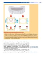
The xenon arc weatherometer has become fairly popular and accepted as giving
a stronger correlation with natural weathering. This is because the wavelength
of light emitted closely matches that of natural sunlight, although higher irradi-
ance is emitted in the 450–500 nm range and above 600 nm. The xenon also
does emit some radiation below 295 nm and must be filtered out for the closest
match to sunlight (Fig. 4). The ASTM J1960 test procedure (47) specifies using
quartz/borosilicate filters (ASTM G-26). This combination does not completely
out the 295 nm radiation and can result in coating failure that does not correlate
with outdoor exposure. Bauer et al. (48) have compared various accelerated
weathering devices for a polyesterurethane coating and concluded that none of
the devices provided output correlating with that obtained with photoacoustic-
FTIR spectroscopy. This was surprising because the Ford test procedure speci-
fies inner and outer borosilicate filters that are supposed to filter out almost all
Performance and Durability Testing 177
F
IG
.4 Xenon arc (quartz/boro) vs. natural sunlight. (Data courtesy of Atlas Mate-
rial Testing Solutions.)
of the radiation below 295 nm (Fig. 5). John Gerlock at Ford Research continues
to evaluate different filtering systems that will allow a very, very close match
to natural sunlight (J. Gerlock, personal communication, 1999).
Certain resins commonly used in formulating flexible coatings are based
on isopthalic acid (IPA). The aromatic nature of this functional group is such it
can be readily attacked by UV light and lead to failure through cracking after
2500 KJ in a xenon weatherometer. Panels of the same coating exposed in
sunlight do not fail by cracking. Therefore, the light in the xenon weatherometer
is inducing chemical changes within the coating that will not occur in reality.
Using the xenon arc to accurately predict the durability of coatings based on
IPA can lead to erroneous and in fact, wrong conclusions. However, altering
the distribution of UV radiation by replacing the quartz/borosilicate filters with
borosilicate/borosilicate filters can eliminate this cracking mechanism and pro-
duce excellent-looking panels after 2500 KJ of exposure (P. V. Yaneff, unpub-
lished results). Unfortunately, many OEM manufacturers still require excellent
xenon results of coating systems on plastic in addition to Florida weathering.
Therefore, based on this criterion, coatings that can perform very well in natural
weathering could never be approved for OEM use because they fail prematurely
when exposed in a xenon weatherometer with quartz/borosilicate filters.
178 Yaneff
F
IG
.5 Xenon arc (boro/boro) vs. natural sunlight. (Data courtesy of Atlas Material
Testing Solutions.)
Many OEMs require coatings for plastics to pass a minimum of 2500 KJ
of exposure in the xenon arc. This takes approximately three months to complete
and appears to correlate with two years exposure in south Florida (49) and
therefore, has an acceleration factor of eight. As the trend for better durability
and appearance retention continues, longer exposure periods of 3500 to 5500
KJ are being specified. The latter requires almost one year of accelerated weath-
ering to complete. Obviously, a xenon weatherometer capable of higher wattage
output, which could achieve 5500 KJ in a relatively shortened time frame, would
be extremely beneficial to the entire coatings industry.
4.4 Quartz Ultraviolet (QUV) Weatherometer
Although UV radiation is usually largely responsible and contributes to a coat-
ing’s photochemical degradation, the type and amount UV radiation emitted
from today’s QUV weatherometers (ASTM G-53) far exceeds that emitted from
natural sunlight. The QUV-B emits UV radiation with a maximum peak at 313
nm (Fig. 6). It also emits some radiation below 295 nm, unlike sunlight, and
can be very devastating to some polymer types. Many coatings used on plastics
can be quickly destroyed and exhibit cracking and/or significant yellowing in
this type of UV exposure. The QUV-A, on the other hand, emits UV light with
Performance and Durability Testing 179
F
IG
.6 Fluorescent UV vs. natural sunlight. (Data courtesy of Atlas Material Test-
ing Solutions.)
a peak at 340 nm and has no output below 295 nm, and is also shown in Figure
6. Many coating systems show better correlation between outdoor exposure and
QUV-A than with QUV-B.
4.5 Carbon Arc Weatherometer
The carbon arc weatherometer is commonly used (ASTM G-23) and specified
by the Japanese OEM companies. The differences between what is emitted from
the carbon arc weatherometer and sunlight are very different (Fig. 7). The car-
bon arc emits higher irradiance in the dangerous 280–310 nm region. Again,
chemistry can be induced through exposure in this type of weatherometer that
will never occur in the real world. Therefore, the basis for using this type of
accelerated weathering device should be cased on established durability correla-
tions, and not just on tradition.
4.6 Equitor ia l Mo un t wi th Mirro rs f or Accelera ti on P lu s Wa te r
Equitorial Mount with Mirrors for Acceleration plus water (EMMAQUA) is a
widely underutilized accelerated exposure test (ASTM G-90). An EMMAQUA
180 Yaneff
F
IG
.7 Carbon arc vs. natural sunlight. (Data courtesy of Atlas Material Testing
Solutions.)
exposure in Phoenix, Arizona can enhance the intensity of natural sunlight by a
factor of eight, comparable to that with the xenon arc weatherometer. EMMAQUA
also can give five times higher UV radiant energy than Southern Florida and its
UV output exceeds the xenon weatherometer (Fig. 8). EMMAQUA exposes
samples to the full spectrum of natural concentrated sunlight and is therefore,
one of the most realistic accelerated weathering tests available and is vastly
underutilized.
4.7 Chemical Test Methodology
Researchers like Gerlock (50) and Bauer (51,52), have spent many years trying
to understand chemically how coatings break down and what test methods can
induce the same chemistry to decompose these automotive coatings. They have
focused on the concept of photooxidation and the use of ultraviolet absorbers
(UVA) and hindered amine light stabilizers (HALS) to reduce or inhibit the rate
of photooxidation (53). They have also developed test methods to produce, ob-
serve, and characterize photooxidation degradation products (54). They have
also integrated other available nonphotochemical techniques such as liquid chro-
matography and mass spectroscopy (55) to characterize various photoproducts and
suggest reaction mechanisms. Examining Florida-exposed panels using photo-
Performance and Durability Testing 181
F
IG
.8 Emmaqua vs. natural sunlight (UV). (Data courtesy of Atlas Material Test-
ing Solutions.)
acoustic ultraviolet (PAS-UV) and photoacoustic Fourier transform infrared (PAS-
FTIR) analysis (56) has proved useful and has provided information on the rates
of photooxidation of various UV screeners in combination with HALS.
Researchers continue to develop and gather data from these scientific test
methods and correlate these findings with that obtained from real-world expo-
sure. The goal is to perform the exact type of chemistry on coated panels in the
laboratory and induce the same type of chemical degradation that results from
exposure, in a very short time. An excellent summary on the use of these nontra-
ditional tests and their correlation with Florida exposure has recently been re-
ported by Gerlock et al. (57). These authors propose adding these nontraditional
tests to the repertoire of paint-weathering performance metrics. Adding these
tests and having the concept accepted by the entire OEM community, would
allow the screening and rapid introduction of new durable coatings with the
needed and expected performance.
5 SUBSTRATE IMPACT
Many people do not realize that the choice of the plastic substrate can have a
profound impact on many of the physical, chemical, and mechanical properties
182 Yaneff
of the painted plastic part. Table 6 shows a comparison of the main substrates
for automotive fascia in terms of acceptance, cost, and processing. Because most
plastics are nonconductive, some sort of conductive layer is needed to maximize
the transfer of paint from a gun to the part. The higher transfer of paint to a
conductive part will be evident in the final finish, which continues to improve
when additional paint is applied to the part.
5.1 Appearance
The use of conductive paints and/or conductive plastics (58) has been shown to
enhance paint transfer and can greatly improve painted-part appearance. The
impact on appearance is easily seen when one examines porous plastics such as
SMC (59) that can be cured at low or high temperatures or plastics containing
high amounts of fillers such as milled glass. Rigid RIM (RRIM) containing 15 to
25% glass used to be a popular choice because it offered the desired mechanical
properties when painted. However, the presence of the glass resulted in a very
rough and porous surface in which glass fibers could protrude through the paint
reducing the DOI and gloss. The move to smooth plastics such as TPO gave
most of the desired mechanical properties but did not suffer from the loss of
DOI when painted. Table 7 shows the impact of substrate type and clearcoat
chemistry on painted-part appearance. Table 8 shows some data for these sub-
strates after 24-months of Florida exposure. Yellowing of the coating can also
result from the choice of plastic (60) and must be fully evaluated.
T
ABLE
6 Comparison of the Main Substrates for Automotive Fascia
Substrate RIM RRIM TPO
Relative cost $$ $$$ $
Smoothness Smooth Rough Smooth
Contains IMR Yes Yes No
Surface tension High High Low
Contains filler for stability None Yes Maybe
Migrating materials Yes Yes Yes
Paint adheres directly Yes Yes Not commercial yet
Offers class A appearance Yes Sometimes Yes
Can yellow topcoat Yes Yes Usually not
Cure requires 250°F No No Yes
Reduces orange peel and DOI Low High Very low
Required primer (usually baked) Yes Yes No
Performance and Durability Testing 183
T
ABLE
7 Effect of Substrate Type and Clearcoat Chemistry
on Painted Part Appearance
Initial gloss Initial DOI
Clearcoat technology 1K Flex 2K Clear 1K Flex 2K Clear
Substrate
Metal 92 87 82 82
Bexloy V 978 91 87 81 80
Noryl GTX 910 92 86 81 80
PUR RIM 66 86 72 78
PUR RRIM 82 85 69 75
PU RIM 84 85 80 78
PU RRIM 81 83 71 74
TPO 92 87 81 83
(1) Basecoat color was light sapphire blue metallic; (2) all substrates were
primed with a black flexible primer and baked for 20 minutes at 250°F; and
(3) basecoat was applied at 0.7 mil and clearcoat at 1.5 mil. Topcoat was
baked for 25 minutes at 250°F.
T
ABLE
8 Effect of Substrate Type and Clearcoat Chemistry on Appearance
Retention
Twenty-four months Florida exposure
% Gloss retention % DOI retention
Clearcoat
technology 1K Flex 1K Rigid 2K Clear 1K Flex 1K Rigid 2K Clear
Substrate
Metal 72 100 99 41 72 112
Bexloy V 978 60 100 98 63 60 120
Noryl GTX 910 60 100 100 81 60 136
PUR RIM 66 100 94 25 66 124
PUR RRIM 82 100 94 52 82 89
PU RRIM 59 100 93 77 59 113
PU RRIM 96 100 92 53 96 109
TPO 88 99 99 61 88 111
(1) Basecoat color was light sapphire blue metallic; (2) all substrates were primed with a
black flexible primer and baked for 20 minutes at 250°F; (3) basecoat was applied at 0.7
mil and clearcoat at 1.5 mil. Topcoat was baked for 25 minutes at 250°F (part temperature);
and (4) panels were exposed 5 degree south (black box) starting in August 1992 for 24
months.
184 Yaneff
5.2 Adhesion
Obviously, not all plastics when coated provide similar adhesive strength. Some
can in fact be extremely difficult to adhere to and considerable experience and
effort are required to develop robust coatings that will adhere under a wide
variety of conditions. As stated in Section 2.2, the surface energy and available
bonding sites on or near the surface both contribute to the observed adhesive
characteristics. Both of these can be greatly altered through processing (61). The
ease with which solvents can penetrate into the plastic will also affect the adhe-
sive strength. Solvent selection can have a major influence on swelling the plas-
tic. In addition, the choice of resin, crosslinker, solvents, and wetting agents can
and will affect the amount of adhesion. The selection and even the development
of new test methods such as compressive shear delamination (62) and the 90°
peel test method (63) will continue to provide information on how to increase
the adhesion of paint to a plastic substrate.
5.3 Gasoline Resistance
The gasoline resistance of coated TPO is dramatically affected by the type and
grade of TPO. Coating systems that perform well on low modulus TPO can
completely delaminate from higher modulus grades. As previously stated,
stronger adhesive formulations are needed to give the expected performance on
these higher modulus grades of TPO (Fig. 9).
5.4 Gouging
Gouging of plastic arose with the introduction of soft plastics like TPO. Opera-
tors who would roughly handle TPO parts and bang them together would gouge
the plastic, giving painted defects known as black scratches. This weakness
made it rather difficult to successfully paint TPO and give the desired appear-
ance without any defect. Over time, paint operators began to handle the soft
substrate with a little more care and completely eliminated in-plant damage. The
cohesive weakness of conventional TPO did not improve when painted and the
part would still gouge when painted. This area has been extensively studied by
Ryntz in terms of TPO morphology and the type of coatings used. While not
recognized as a large warranty issue, TPO gouging is fairly prevalent on today’s
automotive bumpers and greatly detracts from the painted part appearance.
Many TPO suppliers continue to try and increase TPO’s cohesive strength in an
attempt to reduce this unsightly part defect. As previously stated, the shift to
higher modulus materials can significantly reduce the severity and prevalence
of friction-induced gouge damage.
Performance and Durability Testing 185
F
IG
.9 Impact of TPO modulus on gasoline soak.
5.5 Chipping
For the most part, chipping is not very evident on today’s painted parts. The
combination of flexible plastic and flexible paint largely overcomes the ten-
dency to chip, even at low temperatures. However, with the trend to higher
modulus materials, chipping could become an issue. Here again, it is critical to
test the entire painted part system, prior to any change or a new commercializa-
tion.
5.6 Flexibility and Impact Resistance
This is the area where plastic plays a tremendous role in determining painted
part performance. The closer the match in flexibility of the plastic part with that
of the coating used, the better the probability of meeting the expected low-
temperature flexibility and impact performance. For many years, the flexibility
of a painted part was accessed through a mandrel bend test. More recently, the
importance of this test has diminished and has been replaced with the multiaxial
impact test, usually performed at low temperatures. Failure in this test occurs
186 Yaneff
when the falling dart induces brittle failure (i.e., part cracks), as opposed to
ductile failure (i.e., paint cracks).
The trend to thinner-walled, higher modulus TPO diminishes these impact
properties, especially at low temperatures. This movement also reduces the win-
dow for acceptable flexibility as shown in Figure 10. According to Figure 10,
higher modulus TPO is more sensitive to variation in bake time and temperature
and as such, closer control of oven conditions are needed to ensure the required
flexibility specifications will be met. To avoid shatter or breakage of the painted
plastic part, the coating must be made more flexible as the substrate becomes
more rigid, to keep the same low-temperature performance. Unfortunately, prop-
erties such as chemical resistance are reduced with the move to more flexible
coatings. The use of more flexible resins and/or more flexible crosslinkers can
be used as approaches that may help to increase a coating’s flexibility and,
ultimately, impact resistance.
5.7 Scratch and Mar
While not dramatic, plastic selection can influence the degree of scratch-and-
mar damage of a painted part. In many instances, a coating will be softer when
applied to a soft plastic surface. On the other hand, applying it to an unusually
hard plastic surface will render the coating slightly harder. In some respect, the
coating telegraphs the hardness of the surface and takes on some of its character-
istic. Because flexible coatings have better mar resistance than rigid coatings,
F
IG
.10 Impact of TPO modulus on painted part flexibility window.
Performance and Durability Testing 187
applying a flexible coating to a rigid surface will make the surface scratch
less.
5.8 Etch and Chemical Resistance
The choice of substrate can impact the chemical and etch resistance of a coated
plastic part. Thin layers of paint (especially when thin) can be influenced by the
hardness of the substrate. However, this does not generally impact the chemical
resistance of clear-coated parts as measured in testing such as Jacksonville. Sub-
strates that are sensitive to solvents such as acrylonitrile butadiene styrene
(ABS) and polycarbonate/polybutylene terephthalate (PC/PBT) can be rapidly
or slowly degraded when attacked with certain solvents or even basic materials.
6 PAINT TECHNOLOGY IMPACT
Obviously, the choice of substrate, the molding process, the paint technology
used, how the parts were painted, and the particular paints selected can have a
major impact on both performance of the painted plastic part and durability.
Figure 11 illustrates on a relative basis the impact each of these variables can
have on durability. In this particular example, durability was considered as ap-
pearance retention. The movement from the early mono-coat technology to the
current basecoat/clearcoat technology has markedly improved both the perfor-
mance and durability of the coated plastic part. Specifications for OEMs have
increased tremendoulsy thus dictating the need for higher durability products.
6.1 Adhesion Promoters and Primers
The use of a primer to promote adhesion and fill in voids in the substrate can
help to improve part appearance and quality. The use of adhesion promoters on
olefinic substrates such as TPO and PP not only is necessary for adhesion but
also dramatically influences other properties such as gasoline, gasohol, and even
gouge resistance. Adhesion promoters for TPO and polypropylene (PP) are com-
monly chlorinated based polyolefin (CPO) primers (64) that contain a co-resin,
conductive carbon black, and hydrocarbon solvents for optimum CPO solubility.
Other resins can also be beneficial in improving adhesion especially under hu-
midity conditions (65).
Both solventborne and waterborne (66) CPOs are available and both can be
formulated into products meeting today’s needs. Chlorine-free waterborne adhesion
promoters based on maleic anhydride grafted propylene-hexene copolymer have
also been developed and exhibit excellent adhesion and gasoline resistance (67).
Specifications for painted TPO parts have become more stringent over the
past decade forcing the need to control the film build of the adhesion promoter.
Applying the adhesion promoter at 5 to 10 microns is necessary to ensure good
188 Yaneff
F
IG
.11 Impact of substrate, processing, and paint technology on durability retention.