Open-Source Robotics And Proces Control Cookbook Edwards L 242P Newnes Elsevier 2005 Part 10 docx
Bạn đang xem bản rút gọn của tài liệu. Xem và tải ngay bản đầy đủ của tài liệu tại đây (161.57 KB, 20 trang )
168
Chapter 4
FontPath “/usr/X11R6/lib/X11/fonts/Speedo/”
FontPath “/usr/X11R6/lib/X11/fonts/Type1/”
FontPath “/usr/X11R6/lib/X11/fonts/CID/”
FontPath “/usr/X11R6/lib/X11/fonts/75dpi/”
FontPath “/usr/X11R6/lib/X11/fonts/100dpi/”
EndSection
Section “Module”
Load “extmod”
Load “dbe”
Load “dri”
Load “glx”
Load “record”
Load “xtrap”
Load “speedo”
Load “type1”
EndSection
Section “InputDevice”
Identifier “Keyboard0”
Driver “keyboard”
EndSection
Section “InputDevice”
Identifier “Mouse0”
Driver “mouse”
Option “Protocol” “auto”
Option “Device” “/dev/mouse”
EndSection
Section “Monitor”
Identifier “Monitor0”
VendorName “Monitor Vendor”
ModelName “Monitor Model”
HorizSync 31.5 - 50.0
VertRefresh 50.0 - 75.0
EndSection
Section “Device”
#Option “SWcursor” # [bool]
#Option “HWcursor” # [bool]
#Option “NoCompression” # [bool]
#Option “NoAccel” # [bool]
#Option “TV” # [str]
#Option “TV_Output” # [str]
169
The Linux-Based Controller (A Soft Task)
#Option “TVOverscan” # [str]
#Option “ShadowFB” # [bool]
#Option “Rotate” # [str]
#Option “FlatPanel” # [bool]
#Option “ColorKey” # i
#Option “OSMImageBuffers” # i
Identifier “Card0”
Driver “nsc”
Option “NoAccel” “True”
VendorName “Cyrix Corporation”
BoardName “5530 Video [Kahlua]”
BusID “PCI:0:18:4”
EndSection
Section “Screen”
Identifier “Screen0”
Device “Card0”
Monitor “Monitor0”
DefaultDepth 16
SubSection “Display”
Depth 16
Modes “1024x768” “800x600” “640x480” “400x300” “320x240” “320x200”
EndSubSection
EndSection
There are many good reasons to switch to using XFree86 4 if you can, including:
■ Xv and DGA accelerated graphics support.
■ An end to the need to specify weird virtual screen sizes (the Option Display-
Compression setting achieves this).
■ More flexible server options.
■ The default video modes have “friendlier” syncrates than the 3.x server.
■ Translucent mouse cursors.
Now, that’s only half the picture. Due to a bug, the XFree86.org official release
code does not support scandoubled modes (for example, 320 × 240) on Geode. I have
generated a patch for this bug. If you’re interested in the gory details, you can find my
original posting on the topic, with an explanation of the problem, at l-
archive.com//msg00455.html. Here’s the patch:
170
Chapter 4
Begin patch for disp_gu1.c
130a131,135
> /*
> * Bugfix to gfx_is_mode_supported to fix problems with doublescan
modes
> * Lewin A.R.W. Edwards <[EMAIL PROTECTED]>
> */
>
839d843
<
840a845,850
> int tmp_yres;
>
> tmp_yres = yres;
> if (DisplayParams[mode].flags & GFX_MODE_LINE_DOUBLE)
> tmp_yres = tmp_yres / 2;
>
842,843c852,853
< (DisplayParams[mode].vactive == (unsigned short)yres) &&
< (DisplayParams[mode].flags & hz_flag) &&
> (DisplayParams[mode].vactive == (unsigned short)tmp_yres) &&
> (DisplayParams[mode].flags & hz_flag) &&
850a861
>
878a890
>
Begin patch for nsc_gx1_driver.c
150a151,155
> /*
> * Minor patches to allow support of low-res video modes
> * Lewin A.R.W. Edwards <[EMAIL PROTECTED]>
> */
>
475c480
< { NULL, 25175, 135000, 0, FALSE, TRUE, 1, 1, 0 };
> { NULL, 10000, 135000, 0, FALSE, TRUE, 1, 1, 0 };
937c942
< minHeight = 480;
171
The Linux-Based Controller (A Soft Task)
> minHeight = 200;
1850c1855,1856
< if (MemIndex == -1) /* no match */
>
> if (MemIndex == -1) /* no match */
2363a2370
>
Begin patch for nsc_gx2_driver.c
145a146,150
> /*
> * Minor patches to allow support of low-res video modes
> * Lewin A.R.W. Edwards <[EMAIL PROTECTED]>
> */
>
474c479
< { NULL, 25175, 229500, 0, FALSE, TRUE, 1, 1, 0 };
> { NULL, 10000, 229500, 0, FALSE, TRUE, 1, 1, 0 };
911c916
< minHeight = 480;
> minHeight = 200;
Using my patched driver enables 400 × 300, 320 × 240 and 320 × 200 graphics
modes, which are useful if you need to play VideoCD or other low-resolution movie
content on a Geode platform. However, you will still have to contend with the fol-
lowing issues:
■ The NSC driver does not, apparently, fully support autoprobing. This means
that running
XFree86 -configure will not generate a completely valid
XFree86Config file (it will “kinda” work, but it won’t give you a full range of
resolutions and will require some manual tweaking).
■ It appears that the Geode, or at least the X driver for it, doesn’t support DDC so
the monitor syncrates in an auto-generated XFree86Config will be arbitrary.
172
Chapter 4
■ If you’re running with display compression enabled, you may see minor video
glitches onscreen, particularly if your application writes directly to display
memory. This phenomenon appears to be a momentary loss of sync, like a
skipped v-sync pulse, and it is yet another of the problems caused by the
ridiculous “video compression” feature of the CS5530. The line:
Option “NoCompression” “True”
in the Device stanza in your XFree86Config file fixes this.
■ UI rotation is supported using the Option “Rotate” “CW” or Option “Rotate”
“CCW” switches. However, these will fail catastrophically unless you also use
Option “ShadowFB” “true”. This has a fairly severe performance downside
and I don’t recommend it.
■ Flat-panel support appears to be partly broken, at least on the PCM-5820
with current BIOS versions. If you need to use a direct-connect parallel or
LVDS LCD, then for the time being you are probably best off using the VESA
driver. Neither the vanilla XFree86 driver nor my patched driver will work
correctly on most of the LCDs I have tested. The National Semiconductor
server does work, but it doesn’t support scandoubled video modes. (Note, by
the way, that you need to specify
Option FlatPanel True if you are using
XFree86 4.x with an LCD system).
■ The nsc_drv.o driver does not correctly save/restore the entire video subsys-
tem state with some BIOS versions. This makes it impossible to switch from
X to a different virtual console. It also means that the system will lose sync
and go into an undisplayable video mode if you exit X. There is no work-
around for this issue at this time; use XFree86 3.x if this is a problem for you.
This problem is known to exist on the PCM-5820 (all 1.x BIOS versions),
Wafer-582x (all versions) and the e-valuetech EBC-3410. It does not affect
the EBC-5410 with the BIOS versions I have tested to date.
173
The Linux-Based Controller (A Soft Task)
4.7.5 Hybrid and Unusual Interfaces
Choosing a graphics interface method in Linux is quite complicated, because many
of your possible options overlap, and certain combinations of them can coexist hap-
pily on the one system. For example, it’s possible for either svgalib or X to run on top
of the framebuffer device; in fact, embedded ARM-Linux systems with LCDs (such
as PDAs) are almost universally implemented with an X server running on top of the
appropriate framebuffer driver. Even though X is using the framebuffer, there’s noth-
ing to stop your application from writing into video memory directly and only using
X for features that absolutely require it.
I’d like to share with you, briefly, two apparently little-known methods of imple-
menting a GUI, neither of which are talked about very frequently (if at all). I’ve
had success with both of these in commercial products, and I feel that they saved me
considerable time in the applications I was implementing. Each one solves a very dif-
ferent set of problems.
My first suggestion is to include an embedded web browser and a simple web
server on your appliance, and implement as much as possible of the user interface
as web forms processed (through the web server) by a backend program. The great
thing about this method is that you automatically get “free” remote control of the
appliance over a TCP/IP network connection, if available. This technique doesn’t
work well for all types of appliances (for instance, I wouldn’t try it with something
like a digital video recorder), but it does work exceedingly well for implementing the
configuration front-end on an appliance that spends most of its time doing nonin-
teractive things. An example of this would be an electronic advertising sign sort of
application; most of the time, it’s running movies and playing still images, but oc-
casionally the user needs to twiddle the configuration. Another good example is a
machine on a factory floor, controlling some largely automated process such as count-
ing or sorting; you might want to have a local console so that operators can perform
occasional maintenance functions directly at the machine, but mostly you will want
to operate it remotely.
174
Chapter 4
One suitable backend for this type of system is the industry-standard Apache
web server included with most Linux distributions (including Fedora). Although
it’s rather overkill for the type of application we’re discussing, it’s easy to use, it is
easy to write compatible CGI modules in many different languages, and the server is
pre-integrated with the OS distribution, which make it an obvious starting point, if
nothing else.
Choosing a web browser to run locally is a bit more challenging. Mozilla/
Netscape is a grotesque leviathan; it’s slow to start and has an enormous RAM and
disk footprint. It is extremely sluggish on Geode, mostly due to the slow performance
of X in general. Opera is a possibility, but it’s a commercial product and it still doesn’t
have wonderful performance. For the application we have in mind, I recommend
using either Dillo or eLinks Dillo is a small,
reasonably fast X-based browser, and it’s particularly good at rendering pages in a
cosmetically similar fashion to the “big” browsers. This may be important in applica-
tions where the browser will be called upon to render external content in addition
to the local configuration pages. However, if that feature isn’t overridingly important
to you, I suggest eLinks as a better choice. eLinks can run either on the standard
framebuffer console, or as an X application. In either case, it uses its own font-ren-
dering engine, which leads to cosmetically different presentation than you would see
with a more conventional browser. However, it does support a large number of useful
features—secure connections, support for forms, some scripting functionality, and so
on. Since it doesn’t run with an X event model, it also lends itself admirably to being
adapted for use in embedded environments that don’t have traditional input devices.
For example, in one application, I have adapted eLinks to use five pushbuttons for
page navigation; two buttons scroll the page up and down, two buttons select “previ-
ous link” or “next link” (amongst the hyperlinks on the currently visible page), and
the remaining button enters the currently activated link. Holding down that fifth
button brings up a context menu that allows you to move forwards or backwards in
the page history.
My second suggestion contains rather a lot of cheating. For a rather large project, I
needed to implement a system that was able to run a few X applications and could also
run an XFree86-based movie player application that needed to be able to change video
modes and use hardware MPEG playback acceleration. However, the device needed to
175
The Linux-Based Controller (A Soft Task)
present a slightly souped-up version of a proprietary GUI that was originally developed
on a much older product. (The older product was OS-less; it ran on a fairly low-perfor-
mance 32-bit architecture with very little operating system support).
It just so happened that the proprietary GUI portion of this code was already
entirely extant in the older project, so I didn’t want to move it on top of an existing
graphics library. I eventually developed a hybrid sort of system. The machine boots
into XFree86, and launches my application. To cut down on system resource usage,
there is no window manager; the startup scripts simply spawn the X server, pause for
it to finish starting up, then launch my executable. My program then obtains the
starting address of video frame memory, and mmap()s it into its address space (in a
similar manner to the framebuffer example code I described earlier). By making a few
assumptions about video memory layout, it can run the exact same code used in the
older OS-less product. When it needs to provide a function that requires interaction
with X, it simply spawns a subprocess; a movie player, web browser, and other similar
“high-level” applications are all provided.
This ramshackle-sounding system actually works very well, and it allows the
proprietary portions of the GUI to remain portable back to the older, non-PC-based
versions of the appliance. Furthermore, the main application doesn’t have to deal
with Geode’s sluggish X performance.
Quite possibly, neither of these suggestions exactly matches your system needs.
The point I’m trying to make here is that there is room for lateral thinking when
choosing your interface. It’s entirely possible to tailor your user interface technology
to the specific needs of the application you’re trying to implement.
4.8 Infra-Red Remote Control in Linux Using LIRC
There are several sorts of applications where it may be useful to offer infra-red re-
mote control capabilities. The obvious example is a homebrew DVR (digital video
recorder) or TV-top player box for video content downloaded off the Internet. In an
industrial or laboratory setting, however, there are other possible uses for IR con-
trol. For example, you may want to have your electronics in a sealed box to protect
against environmental hazards (water, corrosive chemicals, etc). Your appliance may
be mounted somewhere difficult to reach. Or you may simply want to prevent ran-
176
Chapter 4
dom passersby from tampering with equipment settings—authorized personnel with
the appropriate remote control can still access these settings easily.
Most super-I/O chips, including the Winbond W83977 on our Advantech board,
include an IR decoding function, configurable either for bidirectional IrDA commu
-
nications or for receiving commands from CIR (consumer infra-red) remote controls.
Note that these two functions are very different, and are supported by completely dif
-
ferent software. IrDA is a very complex bidirectional protocol; although some remote
controls use IrDA, almost any consumer remote control you’re likely to acquire will use
a simpler consumer protocol, such as the Philips RC5 code set. In this section, I’ll show
you how to set up your SBC to receive the signals from almost any arbitrary remote
control. The specific remote I’m using in my worked example here is a generic cable
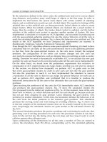
box controller supplied by Infrared Remote Solutions Inc. raredremote.
com/, part IRSI-07-15-01. A sample is shown in Figure 4-2.
Figure 4-2:
Example IR remote
177
The Linux-Based Controller (A Soft Task)
I chose this device to work with because it has the fewest buttons of any remote I
own, thus making for a nice simple example. For convenience, I will refer to the but-
tons (from upper left to lower right) as 1, 3, W, A, S, D, and X—because this layout
can nicely be emulated on a QWERTY keyboard with a roughly similar button lay-
out. You may prefer to use a universal remote, in which case you can simply pick an
appliance type and model (say, Sony® DVD player) and follow the remote’s instruc-
tion manual to set the universal remote to emulate the controller for that device.
This technique has the advantage of ongoing reproducibility; you can be fairly sure of
being able to acquire a steady supply of an off-the-shelf universal remote—and even
if your specific model is discontinued, you will be able to switch to another model as
long as it handles the same appliance types.
Let’s begin with a thumbnail description of how an infra-red remote operates:
The remote control itself consists of a key matrix, an application-specific micro-
controller, and an IR LED. When a key is depressed, the microcontroller generates
a sequence of bursts of carrier signal, typically somewhere between 30~40 kHz—in
our case, 38 kHz. The burst sequence encodes a button ID; these codes are arbitrarily
mapped to appliance functions. There are several common encoding protocols, and
most of these protocols include some kind of subprotocol to differentiate between
multiple devices of the same type.
On the receiver side, it is normal to use an integrated IR receiver module as the
front-end, rather than assembling something out of discrete components. An exam-
ple of the sort of component you would find here is the Vishay TSOP12xx or Sharp
GP1U series of parts. In general, these receiver modules consist firstly of an optical
IR filter and photodetector. In the case of the Sharp and Vishay devices, the housing
is simply molded out of an IR-transparent resin. Some older modules were con-
structed of metal with a small IR-transparent window at one end. This hardware is
followed by, at minimum, a bandpass filter centered on the nominal carrier frequency,
and a demodulator circuit that turns the carrier frequency into a solid logic level,
normally HIGH (or high-impedance) for no carrier, and LOW for carrier detected.
Most available detector modules have a little extra intelligence in them to reduce
noise sensitivity by ignoring extremely short carrier bursts.
178
Chapter 4
Note that there are two compatibility parameters here: the sensitive band of
the IR detector (and the transparent range of its associated filter) must include the
output wavelength of the LED in your selected remote, and the detector module’s
filter frequency must match your remote’s carrier frequency. In practice, you will find
that the sensitive band of the detector is wide enough to cover any IR LED you can
purchase, so you generally don’t need to worry about it. There is also a fairly wide
range of acceptability in the carrier frequency parameter, and again you’ll find that
almost any receiver module will appear to work with most remote controls. However,
the sensitive range and view angle of the sensor will be reduced, perhaps severely,
the more deviation there is between your remote’s carrier frequency and the receiver
module’s nominal frequency.
By the way, there is a significant exception to the statements I just made: In an
effort to reduce error rates for high-speed data transfers, some IrDA transceiver mod
-
ules filter out consumer remote signals very effectively. You may run into this issue
if you’re attempting to embed your application on a laptop or other appliance that
already has its IR receiver built in. The only way you can work around this sort of
problem is by using a different receiver module.
Tip: Sometimes while debugging you’ll find yourself wondering if the IR trans
-
mitter is actually sending anything. There are IR-sensitive cards sold for detecting
these kinds of emissions, but if you don’t have one, you can also use almost any
digital camera or camcorder with an electronic viewfinder (as opposed to a simple
optical viewfinder). Just point the camera at the remote and look at the viewfinder
screen; IR output will show up as a bright blue-white light. The CCDs used in con-
sumer cameras are quite sensitive to long wavelengths; although cameras have filters
in them to remove ambient IR light, the output of the remote’s LED is strong enough
to pierce through this filter.
Before we go any further, we need to connect an IR receiver module to our
SBC. For the remote I specified, we can use the Sharp GP1UV701QS or Vishay
TSOP1238 receiver, or an equivalent part (the vital criteria being +5 V supply
compatibility, and 38 kHz carrier frequency). On the PCM-5820, the IR interface is
CN7, which is a five-pin, 2mm-pitch single-in-line connector manufactured by JST.
The correct mating connector is JST’s PHR-5
28
. Hirose (HRS) makes a visually very
similar but tragically incompatible connector; beware! The pinout is as follows:
179
The Linux-Based Controller (A Soft Task)
Pin Name Description
1 Vcc +5 V supply for transceiver or receiver module
2 NC No connection (but see the following note)
3
IR_RX Demodulated data input to SBC (connect to output pin
of receiver if using a 3-pin receiver module)
4 GND Ground
5 IR_TX IR LED control signal for IrDA transmission
NOTE: This pinout is almost standardized. However, some other boards (for
example, the BCM EBC-5410) use pin 2 for a dedicated CIR input. Advantech has
chosen not to implement the dedicated CIR functionality provided by the Winbond
Super I/O. If you are using a consumer infra-red receiver module on a non-Advan-
tech board and you have reception problems, try connecting your IR receiver’s output
to pin 2 instead of pin 3.
Now we need to look at the software support required to make use of this detec-
tor. Before doing anything further, however, you need to ensure that the Winbond
super-I/O chip on the SBC is configured for IR reception. Go into CMOS setup and
navigate to the “INTEGRATED PERIPHERALS” page. Configure the following set-
tings
29
:
■ Onboard Serial Port 2: Disabled
■ Onboard IR Controller: Enabled
■ IR Address Select: 2F8H
■ IR Mode: IrDA
■ IR Transmission delay: Enabled
■ IR IRQ Select: 3
28
Tip: The crimp tool for these connectors is quite expensive, though the parts themselves are dirt
cheap. You can either improvise with a pair of pliers or a different crimp tool (your results won’t be
very strong; reinforce with hot-melt glue) or alternatively salvage one from something else. In many
CD-ROM drives and portable audio CD players, the connector you need is used to connect the hub
motor to the main PCB. If you have a dead one of these appliances lying around, look inside it!
29
These settings are correct for BIOS version 2.00—older BIOSes have slightly different options and
a spelling mistake or two. The important features are: IrDA mode, I/O address 2F8 (COM2), IRQ 3,
and ensure that the real COM2 port is disabled.
180
Chapter 4
With this accomplished, we’re ready to compile and install the Linux IR re-
mote-control software, LIRC. You’ll find the sourcecode archive on the CD as
/linux/lirc-0.6.6.tar.gz.
LIRC consists of several components and addons, of which three are of principal
interest to us. First is the kernel module that talks to the IR UART and pipes the
mark-space burst data to the next overlying software layer. The lirc project supports
several different types of IR interface; the one we’ll be using is lirc_sir. Then we have
lircd, a daemon that runs in the background and listens to the kernel module, trans-
lating the mark-space codes into a standardized data format via a configuration file
that describes the particular remote control transmitter you’re using. Lastly, we have
irrecord, which is a test program used to analyze an unknown remote control and
generate a lircd configuration file that will work with it.
We begin by configuring, compiling and installing the kernel-mode driver. First,
extract the lirc source archive and run the configure script. Assuming the CD-ROM
accompanying this book is mounted at /mnt/cdrom:
cd /usr/src
tar zxvf /mnt/cdrom/linux/lirc-0.6.6.tar.gz
cd lirc-0.6.6
./configure
In the top-level configuration dialog, select option 1 (Driver configuration) and
press Enter. Navigate down to option 6 (IrDA hardware) and press Enter. Select
option 1 (SIR IrDA) and press Enter. Navigate down to “COM2 (0x2f8, 3),” press
Space to select it, and press Enter. You’ll be returned to the main menu; select option
2 (Software configuration) and press Enter. Make sure that all five options here are
unchecked, and select OK. You’ll be back at the main menu once more; select option
3 and press Enter. You’re now ready to build and install the LIRC module with make
; make install.
At this point, you should also edit /etc/modules.conf and add the line:
alias char-major-61 lirc_sir
181
The Linux-Based Controller (A Soft Task)
Note, by the way, that it’s also possible to specify options in modules.conf to over-
ride the compiled-in driver defaults. However, we already set the driver up correctly
for our hardware during the configuration phase, so we don’t need to add any over-
rides.
In order to use the IR capabilities of the serial port, we have to make sure the
port in question isn’t attached to the Linux serial driver. There are basically three
ways of doing this: don’t load the kernel serial port driver (leave it out of the kernel),
unload the driver (which requires that you have built it as a module), or force it to
relinquish the port we’re using for IR. The last method is the simplest, and can be
achieved (on the PCM-5820) with the command
setserial /dev/ttyS1 uart
none. Now, type modprobe lirc_sir to load the IR driver module
30
. If you get an
error that the module couldn’t be found, manually edit /lib/modules/2.4.24/modules.
dep and add a dependency line that reads:
/lib/modules/2.4.24/misc/lirc_sir.o:
At this point, we have the basic driver infrastructure working, and before going
any further, we need to teach LIRC about the characteristics of our remote control,
using the irrecord utility. Run
irrecord -f /etc/lircd.conf to start the training
process. Note that this command line forces irrecord to run in a “dumb” raw mode.
Due to hardware or possibly firmware-induced glitches on the PCM-5820, you
MUST use this raw mode to train a valid configuration. If you are running on a
non-Advantech SBC (or if you are performing this experiment on a laptop), feel free
to omit the –f parameter. You’ll get a more flexible and much simpler configuration
file.
30
It isn’t normally necessary to load the port driver module manually like this. If you set up the de-
vices in /dev and the alias line in modules.conf, then starting the lircd daemon should automatically
load the appropriate port driver. I’ve detailed the process here manually so you can see immediately
if there is a problem with the port driver, rather than getting a cryptic error out of lircd when you
come to run it later. But it’s good practice to load your expected driver manually anyway—that way
you can provide more meaningful black-box information when something goes wrong.
182
Chapter 4
When you run irrecord, you will first be prompted to read a couple of pages of
information; press Enter twice to skip past this and start recording. In the first stage
of this process, you’ll be asked to hold down each button on the remote for at least 1
second. Dots will appear on the screen to indicate that irrecord is successfully receiv-
ing data from the remote control. This process continues until you’ve completed a
full line of dots. (If there aren’t enough buttons on your remote to meet this condi-
tion, you can press the same button multiple times. The important thing is to be sure
you’ve given irrecord a good sample of the different codes generated by your remote).
Once you’ve completed a full line of dots, if you’re not using raw mode, irrecord
will proceed to the second stage of learning. Again, you should go through every
button on the remote, holding each one down for at least a second. If everything is
working correctly at this point, holding down each button should generate only one
dot, even if you hold down the button for a considerable time. As before, this second
stage continues until you have covered an entire screen line with dots.
At this point, we begin assigning names to the buttons. Simply enter a text label
for the button to be “learned” and press Enter. Irrecord will prompt you to hold down
the button in question, and will start listening for a code on the IR port. For some
types of remote (not the specific one we’re using, though), irrecord should say “Got
it.,” followed by the message “Signal length is [integer]” for each learned button.
These signal lengths should be similar for all the buttons on your remote; if you sud-
denly get a very short signal length (typically 1), this means that a glitch interrupted
the learning process. You should re-teach LIRC that button—just enter the same
button name again, let LIRC recognize it, and manually edit the configuration file to
remove the erroneous entry after you’ve finished with irrecord. You’ll recognize the
bad entry because it will be very short in comparison with the good entries.
Depending on what sort of remote you were training, you may now be prompted
to press a single button repeatedly as fast as you can, so that irrecord can check for
toggle bits. Some IR protocols include a spare bit in each button ID code, which is
toggled each time you press the button. The purpose of this bit is to detect when a
continuously-repeated signal is temporarily interrupted by a physical obstacle. To
demonstrate this feature in operation, point your TV remote at the set, press and
hold the power button, and wave your hand in front of the remote’s LED. Note that
the TV set doesn’t go off and on as you uncover the LED!
183
The Linux-Based Controller (A Soft Task)
Note: It is extremely important that your IR environment is as quiet as possible
while training LIRC to recognize a new remote control. Although the receiver mod-
ule does have some hardware intelligence in it to filter out spurious signals, under
normal conditions it is common for glitches to make it all the way through to the
SBC. Fluorescent lights, including energy saver compact fluorescent bulbs and the in-
ferno of nuclear fusion that beats in on us through unshaded windows (if you happen
to be on the day-side of the terminator) are particularly evil sources of noise. If you
are having trouble teaching LIRC, try darkening the room or covering the remote
and IR receiver with a towel and working by feel under the towel.
If you care to examine the configuration file generated by this process, you will
see a small header followed by a stanza of information for each trained button. For
instance, the stanza describing the 1 button would look something like this:
name 1
39 13507 39 1086 39 2222
39 1086 39 1086 39 1085
39 1085 39 1086 39 2223
39 2221 39 2225 39 1084
39 1086 39 2223 39 1085
39 1085 39 1086 39 1085
39 1086 39 1084 39 1087
39 1085 39 1086 39 1084
39 1085 39 2224 39 2223
39 2222 39 2223 39 2222
39 2224 39 2223 39 2223
39
This represents a header pulse (the 39 13507 leadin), followed by a 32-bit button
code, MSB first. Our remote uses the sequence 39, 1086 to represent a zero and 39,
2222 to represent 1 (note the slight variances in the data above; LIRC offers a “fuzzi-
ness” parameter allowing you to tweak just how much “wobble” is acceptable in the
burst lengths). Thus, the actual code being transmitted for this button is, in binary,
184
Chapter 4
0100 0001 1100 1000 0000 0000 1111 1111—or 0x41C800FF. (In fact, the 0x41C8
header is a vendor-specific code used to distinguish our OEM remote from other
remotes using the same protocol; only the last 16 bits of the button code are actually
useful data).
The long format you just saw illustrated is a very verbose way of describing the
button code. In a configuration file that wasn’t recorded in the dumb raw mode,
LIRC simply defines what is recognized as “1,” what is recognized as “0,” the common
prefix, if any (0x41C8 in our case) and some other information about how the but
-
ton presses are encoded. It then describes each button simply with the hexadecimal
number that’s being transmitted by that button; 0x00FF in the case in the preceding
paragraph. These sorts of configuration files are much easier to read and edit, but un
-
fortunately the Advantech board can’t work properly with them. It’s unclear at this
time whether this is a hardware issue or a BIOS bug, but it seems to be a BIOS issue
since the exact same software configuration can be made to work on other Geode
boards with the same hardware.
You should now test that your configuration file is valid by running the LIRC
daemon,
lircd, and then starting the “watcher” program irw. Once irw is running,
aim the remote at the sensor and press a few buttons. You should see output some-
thing like this (one line of output for each button you pressed):
0000000000000001 00 1 /etc/lircd.conf
0000000000000005 00 s /etc/lircd.conf
0000000000000007 00 x /etc/lircd.conf
The four fields in this output are: the 64-bit code of the button being pressed, the
repeat count, the name you assigned to this button during training, and the name of
the remote control. You can edit the name of the remote in the configuration file; for
example, you can rename it from the default “/etc/lircd.conf” to, say, “dvd-remote.” If
you then concatenate multiple lircd.conf files, lircd will recognize
all the defined but-
ton codes and will inform you not only the code of the button that’s being pressed,
but also which remote control it’s on. This is handy if, for example, you have trained
LIRC to recognize remote controls for both a VCR and a DVD player, and you need
to determine which “Play” button has been pressed.
185
The Linux-Based Controller (A Soft Task)
Note that for a configuration file recorded in raw mode, the button code simply
represents the position of the button description within the configuration file; the
first button encountered is numbered “1,” the next “2,” and so on. If you are using a
“smart” configuration file, the button code will be the actual binary data for the but-
ton; for our remote, this will be a number of the form 0x0000000041C8????, where
???? represents the button code. This detail isn’t particularly important, however, as
we will be working with the names we assigned the buttons, rather than their raw
codes.
Now it’s time to integrate IR support into our own application. Because of the
unusual limitation of the Advantech IR hardware, I’m going to illustrate only non-
repeated keystrokes. The raw configuration file we generated earlier won’t recognize
held-down buttons; it will recognize the first press, but not subsequent repeat events.
This is roughly equivalent to having a rigorously debounced pushbutton mounted on
your appliance.
In order to listen to the lircd daemon, we must open a connection to /dev/lircd.
From this we obtain a regular file stream from which we can read incoming button
data, in exactly the same text format displayed by irw during the tests we just per-
formed. Let’s suppose we only want to read the buttons defined for the remote control
I described earlier. Following is a complete suite of functions for reading the IR
stream and implementing a buffer of incoming button presses. The main limitation
of this set of functions is that it only works when you have defined unique single-
character names for each button on the remote.
To use these functions, first call Init_LIRC(). This function opens a connection
to lircd and then clones off a separate process that continuously runs the Do_LIRC()
function. Do_LIRC() doesn’t chew overly much CPU time, because it spends most
of its time blocked on the read operation, waiting for data from lircd. To get a good
idea of how much jitter this task introduces to your system, create a main loop that
strobes a bit on the parallel port, then sleeps for, say, 100 ms and repeats the pro-
cess indefinitely. Put your scope on the pin of interest, with a slow sweep rate, and
observe how the system behaves when you’re pressing IR buttons. (Try not to have
anything else running. Pagefile access, in particular, will mess up your results here).
If everything is working properly, you should see that incoming IR doesn’t interfere
very much, if at all, with system timings.
186
Chapter 4
// This buffer stores incoming “keystrokes”.
char input_buffer[16];
// Socket for communication with the LIRC daemon
int lirc_fd;
// Stack area for the LIRC subprocess
unsigned char LIRCstack[8192];
/*
Insert character to head of keyboard buffer and push others down
*/
void CON_Buf_Insert(char c)
{
int i;
for (i=1;i<sizeof(input_buffer);i++)
input_buffer[i] = input_buffer[i-1];
input_buffer[0] = c;
}
/*
Check for presence of a character in buffer; don’t remove it
Returns nonzero if there is a character waiting in the buffer
*/
int CON_Count_Buffer(void)
{
int i = -1;
if (!input_buffer[0])
return 0;
for (i=0;i<sizeof(input_buffer) && input_buffer[i]; i++)
return i;
}
/*
Flush input buffer
*/
void CON_Buf_Flush(void)
{
memset((char *) input_buffer, 0, sizeof(input_buffer));
}
187
The Linux-Based Controller (A Soft Task)
/*
Get key
Returns character from head of keyboard buffer [and moves buffer
up one step!]
or 0 if no character is available.
*/
char CON_Buf_Get(void)
{
int i;
char c;
if(!input_buffer[0])
return 0;
c = input_buffer[0];
for (i=0; i<sizeof(input_buffer) - 1; i++)
input_buffer[i] = input_buffer[i+1];
input_buffer[sizeof(input_buffer) - 1] = 0;
return c;
}
/*
Get key (wait if none available)
*/
char CON_Buf_GetWait(void)
{
char c = 0;
while(!c) {
c = CON_Buf_Get();
}
return c;
}
/*
Subprocess to communicate with LIRC
*/
int Do_LIRC(void *p)
{
char buf[128];
while (1) {
int cr;