McGraw-Hill- PDA Robotics Part 8 pptx
Bạn đang xem bản rút gọn của tài liệu. Xem và tải ngay bản đầy đủ của tài liệu tại đây (579.77 KB, 20 trang )
8. 8-pin DIP switch
9. 18-pin DIP IC socket (Note the PIC16F876 is using two—one cut
down)
10. 6-post 2.5 mm DIP headers
11. 20.0000 MHz crystal
12. 11.0592 MHz crystal
13. 1-pin header for analog input
It is good practice to check the conductance after soldering a compo-
nent to the board. This ensures that electricity will flow between the
points on the circuit and with little resistance. If conductivity is poor,
it means that the solder joint is poor and should be redone. To check
for conductivity, set the multimeter to RX 1 KΩ, and touch one probe
on the solder weld and the other on a trace to which it is connected.
PDA Robotics
118
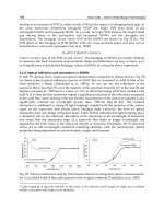
Figure 6.10
Enlarged view of left side of main board.
PDA 06 5/27/03 8:37 AM Page 118
The needle on the meter should “spike” to the right, showing zero
resistance. Figure 6.12 shows the meter set to RX 1 KΩ, with the leads
crossed and the needle to the far right, indicating that there is no
resistance and that the meter is working properly. Figure 6.13 shows
testing the conductivity of the solder connections.
Chapter 6 / Building PDA Robot
119
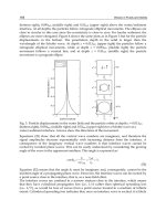
Figure 6.11
Enlarged view of
right side of main
board.
Figure 6.12
Setting the meter
for conductivity
testing.
PDA 06 5/27/03 8:37 AM Page 119
To ensure a good solder joint, keep the tip of the iron clean. Buy high-
quality fairly thin solder, and ensure that the iron is hot. Clean the tip
after soldering two or three joints.
Placing and Soldering the
Motor Controller Components
Figures 6.14 to 6.16 show the placement of the parts on the motor con-
troller circuit. The following numbers correspond to those on the
motor controller circuit board. Ensure that the diodes are oriented cor-
rectly, as shown in the figure.
1. Molex 3.9 mm 2P headers with ramp connects to Molex .156"
wire connectors
2. .1 UF capacitors (or higher)
3. 4007 746 diodes
4. 6-post 2.5 mm DIP headers
5. L298N dual bridge driver
PDA Robotics
120
Figure 6.13
Testing the solder
connections on a
prototype circuit.
PDA 06 5/27/03 8:37 AM Page 120
Chapter 6 / Building PDA Robot
121
Figure 6.14
Parts placement on the motor controller circuit board.
Figure 6.15
Close-up of left side
of the motor
controller.
PDA 06 5/27/03 8:37 AM Page 121
The Infrared Transceiver
Solder the 6-post 2.5 mm DIP header to the board normally, with the
long pins on the top of the board. Position the TFDS4500 on the pads
on the bottom of the board, ensuring that the middle of the transceiv-
er is centered over the middle of the pads. Solder or epoxy the pins to
the pads being careful to not short any of the pads. Ensure that you are
using a good conductive epoxy. Figure 6.17 shows the TFDS4500
lined up and ready for the epoxy or solder to be applied. Note: If using
PDA Robotics
122
Figure 6.16
Close-up of right
side of the motor
controller.
Figure 6.17
Close-up of the
TFDS4500 ready to
be soldered or
epoxyed to the
board.
PDA 06 5/27/03 8:37 AM Page 122
epoxy, gently scrape off the photoresist (which protects the pads from
corrosion) in order to achieve a good contact. A small flathead screw-
driver works well for this. Once the solder or epoxy has set, it is a good
idea to cement the backside of the transceiver with a regular noncon-
ducting epoxy.
Set the boards aside until ready to drill the mounting holes. I recom-
mend putting them in a static-proof bag. We will mount the boards to
the craft once the other steps, such as creating the ribbon cables and
drilling the holes in the support pieces, etc., are done.
The Power Connectors
The Battery Packs
To prepare the power connectors for the battery packs, motors, and the
IR range finder, you will need to solder the Molex .156" (3.9 mm) wire
connectors and slide them into the plastic moldings provided. Figure
6.18 shows the connectors of the battery packs. Note: the ground wire
is always inserted on the left side of the connector. You may want to
solder on/off switches between one of the leads. I simply plug and
unplug the power connectors to the posts to turn the craft on or off.
Chapter 6 / Building PDA Robot
123
Figure 6.18
The power
connections.
PDA 06 5/27/03 8:37 AM Page 123
The IR Range Finder
The connector that comes with the Sharp GP2D12 needs to have the
power leads connected to the 3.9 mm Molex wire connector as well.
Solder the black and red wires to the inserts the same way as the
battery leads, with the ground wire on the left. The blue wire on the
connector goes to the analog input. I improvised a connector for the
solitary analog input pin of the PIC16F876 by using a 3.9 mm connec-
tor turned around with the end that normally has the wire soldered to
it, crimped to fit the pin. This works well because the connector is
secured to the pin by the flexible metal tab. Figure 6.19 shows the sol-
dered connections.
Figure 6.20 shows the improvised connector snug on the PIC16F876
analog input pin.
The two motors will also need to have the Molex power connectors
fastened. But first, we must assemble the gear boxes and drill the holes
that the wires will feed though from the bottom of the PDA Robot.
PDA Robotics
124
Figure 6.19
The IR range finder
connections. A:
Positive (red), B:
Ground (black), C:
Analog line (blue).
PDA 06 5/27/03 8:37 AM Page 124
Cutting the Aluminum Pieces
and Drilling the Holes
Cut the bottom plate (main platform) into an 8" ϫ 6" piece. Cut the top
plate that is suspended on four hex spacers to 7" and 5-1/4". Drill out
the holes, as outlined in Figures 6.21 and 6.22.
• Aluminum: 8" ϫ 6" ϫ 1/16" (main platform)
• Aluminum: 7" ϫ 5-1/4" (top platform) ϫ 1/16"
• Aluminum: 1" ϫ 1/2" ϫ 1/4" (accessory mount)
• Two Tamiya six-speed geared motors (www.hvwtech.com)
• Three Tamiya wheel sets
• Four 1" L-brackets
Mount the hex brackets on the top of the platform. Mount the motors,
wheel brackets, and range finder on the bottom. Figure 6.23 shows the
underside with the motors and wheels mounted to the platform. The
2" hex spacers secure the outside bolts used to mount the motors.
Ensure that both motors are oriented in the same direction. If they
aren’t, the PDA control software will have to be modified to control
the direction of PDA Robot’s motion. Figure 6.23 shows the underside
of the main platform with the motors, range finder, and wheels mount-
ed. The two pieces of balsa wood under the motor gearboxes raise the
Chapter 6 / Building PDA Robot
125
Figure 6.20
The IR analog input
connector.
PDA 06 5/27/03 8:37 AM Page 125
PDA Robotics
126
Figure 6.21
Main platform drill
diagram.
Figure 6.22
Drilled out platform
showing par ts
placement.
PDA 06 5/27/03 8:37 AM Page 126
motors so that they are higher than the outer wheels. This ensures
good traction so PDA Robot can turn easily.
Assembling the Geared Motors
I chose the Tamiya six-speed gearbox for this project and set the gear
ratio to 76.5:1. This gives the craft enough power to move over dense
carpet at a reasonable speed without stalling. The gear kit comes with
detailed instructions on assembling the motors. Figure 6.24 shows the
step in the assembly instructions detailing the gear placement for the
76.5:1 ratio (132-rpm). Figure 6.25 shows the assembled gearbox.
To mount the wheels on the gearboxes, insert the spring pin and use
wheel hub #2 provided with the sports tire set, and fasten the wheel
to the shaft using the hex wrench that comes with the kit. Figure 6.26
shows how to mount the wheel hub on the shaft. Figure 6.27 shows
the mounted gearbox with the wheel attached.
Chapter 6 / Building PDA Robot
127
Figure 6.23
Underside of the
main platform.
PDA 06 5/27/03 8:37 AM Page 127
Once the gearboxes have been mounted, push the motor wires through
the holes and solder the Molex wire connectors to the leads. Ensure
that the ground wire is inserted on the left of the plastic housing. See
Figure 6.22.
PDA Robotics
128
Figure 6.24
Assembling the gearbox.
Figure 6.25
The assembled
gearbox.
PDA 06 5/27/03 8:37 AM Page 128
Secure the L-brackets and mount the wheels using wheel hub #1 and
a 1" 4-40 bolt with a washer so that there is not too much wobble.
Figure 6.28 shows the side profile. Note: You may want to substitute
the L-brackets for casters that will allow the front and back wheels to
swivel freely. I found that the L-brackets work well on smooth surfaces
Chapter 6 / Building PDA Robot
129
Figure 6.26
Mounting the wheel
hub.
Figure 6.27
Mounted gearbox
with wheel
attached.
PDA 06 5/27/03 8:37 AM Page 129
or loose surfaces such as ceramic tile and gravel. The wheels may grab,
hindering the turn ability of PDA Robot when the carpet pile is not
low and tight. Another solution is to use smooth, hard plastic wheels
on the front and back that don’t grab.
Drill holes in the circuit board to correspond with the hex spacers
attached to the main platform, and mount them with 4-40 bolts. Pass
the IR range finder wire through the wire hole in the center of the plat-
form, and insert the presoldered wire connectors into the plastic
Molex housing.
The Ribbon Connectors
To connect the main board to the IR transceiver and the motor con-
troller, we need to prepare the ribbon connectors. For the main board
to motor controller connection, cut a 6" piece of ribbon six wires wide,
and secure the connector to it by sliding the wire into the groves and
pressing down on the top firmly until it is tight. Then slide the lock-
ing key in to hold everything together permanently. It is important that
pin 1 of each connector goes to pin 1 of the other. Secure one connec-
tor to the ribbon, flip it over and connect it the same way on the other
side. The red wire (wire 1) is always on the left. Figure 6.29 shows the
process of preparing the ribbon connector. Do the same for the IR
transceiver. A shorter piece of cable about 4" should work.
It is important that the connectors are placed in the correct orienta-
tion or the circuit will not function. The pins of one connector must
match up with the pins of the other. Figures 6.30 to 6.33 show the
connector’s orientation and how the cables should be aligned. As a
general rule, the red wire (wire 1) should always be over pin 1 of the
connector.
PDA Robotics
130
Figure 6.28
Side profile of PDA
Robot.
PDA 06 5/27/03 8:37 AM Page 130
Attach all the connectors and drill the holes in the top plate that will
support the PDA. Figure 6.34 shows the position of the drill holes
used to secure the top platform (7" ϫ 5-1/4") to the hexagon spacers of
Chapter 6 / Building PDA Robot
131
Figure 6.29
Preparing the ribbon
connectors.
Figure 6.30
The IR transceiver
connector
orientation.
PDA 06 5/27/03 8:37 AM Page 131
PDA Robotics
132
Figure 6:31
The IR transceiver
connector
orientation to main
board.
Figure 6.32
The motor controller
connector
orientation on the
motor board.
PDA 06 5/27/03 8:37 AM Page 132
Chapter 6 / Building PDA Robot
133
Figure 6.33
The motor controller
connector
orientation on the
main board.
Figure 6.34
Top platform drill
holes.
PDA 06 5/27/03 8:37 AM Page 133
the main platform. Secure a piece of sticky Velcro to the top plate
(where you would like the transceiver to go) and to the transceiver
itself. We need to program the 16F876 microcontroller, so it’s best to
leave the top plate off until this is done (see the next chapter).
The Camera (Accessory) Mount
Drill two holes in the 1" ϫ 1/2" ϫ 1/4" piece of aluminum. One hole is
used to secure it to the hex spacer positioned on the front of PDA
Robot and the other to mount the camera. Figure 6.35 shows the cam-
era mount attached to the hex space. A X10 wireless video camera will
be mounted here to provide vision when PDA Robot is being con-
trolled remotely from a PC connected to the wireless network.
Now that PDA Robot’s physical body is complete, we need to give him
a brain. Information on how to program the microcontroller and the
PDA software is in the chapters to follow. Figures 6.36 and 6.37 show
PDA Robot fully assembled.
PDA Robotics
134
Figure 6.35
Camera mount
attached to the 2"
hex spacer.
PDA 06 5/27/03 8:37 AM Page 134
Chapter 6 / Building PDA Robot
135
Figure 6.36
PDA Robot being
controlled by a Palm
OS device (Visor
Deluxe).
Figure 6.37
PDA Robot being
controlled with a
Pocket PC device
(iPAQ).
PDA 06 5/27/03 8:37 AM Page 135
This page intentionally left blank.
137
The PIC compiler is used in this project to write the software running
on the PIC16F876 microcontroller, and the EPIC Plus Programmer is
used to download the software to the PIC16F84A. The PIC16F876
receives input data and commands from the infrared (IR) module and
the PDA via the MCP2150. It sends information such as range data and
motor control confirmation codes back to the PDA. The PIC16F876
could be considered the main node of the robot’s nervous system.
Figure 7.1 shows the EPIC Plus microcontroller programmer with the
PIC16F876 inserted into the ZIF adapter.
The pocket-sized EPIC Plus Programmer quickly and easily programs
most PICmicro microcontrollers, including the PIC16C55x, 6xx, 7xx,
84, 9xx, PIC16CE62x, PIC16F62x, 8x, 87x, PIC14Cxxx, PIC17C7xx,
PIC18Cxxx, 18Fxxx, the 8-pin PIC12Cxxx, PIC12CExxx, and the 14-
pin 16C505 microcontrollers. The basic programmer includes an 18-
pin socket for programming 8-, 14-, and 18-pin PICmicro microcon-
troler unit (MCUs). (It will not program or read the baseline PIC16C5x
or high-end 17C4x series.) A wide variety of adapters allow the EPIC
Plus to program devices in many different package formats such as
DIP, SOIC, PLCC, SSOP, TSOP, etc.
The EPIC Plus Programmer is software upgradeable for future PICs. It
includes DOS and Windows 95/98/Me/NT/2000 programming soft-
ware and a PIC macro assembler that works with both the Microchip
Programming
the PIC16F876
Microcontroller
7
PDA 07 5/27/03 8:44 AM Page 137
Copyright 2003 by The McGraw-Hill Companies, Inc. Click Here for Terms of Use.