Field and Service Robotics - Corke P. and Sukkarieh S.(Eds) Part 15 potx
Bạn đang xem bản rút gọn của tài liệu. Xem và tải ngay bản đầy đủ của tài liệu tại đây (7.51 MB, 40 trang )
568 N. Elkmann et al.
of water will be discharged into the sewer constantly. Legal guidelines require a
sewer system’s structural and operational condition be inspected and recorded
on a scheduled, regular and systematic basis. At present, structural condi-
tion is usually detected by optical inspection (TV inspection or walk-through
inspection).Conventional inspection methods cannot be used to inspect the
Emscher sewer system because of its constant partial filling. The automatic
inspection and cleaning systems to be designed as part of the project should
effectively do away with walk-through sewer inspections. Hence, among other
things, approval of the one-pipe sewer will depend on demonstrating that in-
spection and cleaning can be done by using remote controlled or automatic
systems.
As part of the project, the following main components were designed and
tested for their feasibility and fulfillment of the requirements:
• Carrier system (motion kinematics, robot) for positioning along the sewer
line;
• Sensor and measuring systems for inspecting pipe condition above and
below the water line as well as for detecting deposits;
• Sewer cleaning system;
• Media supply (power, data communication, water, etc.);
• Control system, operation;
• System navigation and positioning in the sewer;
• Handling systems for positioning sensors and cleaning tools on and along
the sewer wall.
A large test station with various reinforced concrete pipes and different types
of damage (e.g. cracks or spalling) was set up at the Fraunhofer Institute IFF
in Magdeburg. The sensors for inspection were mostly new developments.
In consultation with the Emschergenossenschaft, the Fraunhofer IFF has
developed and built a prototype of the rough inspection system as well as a
test prototype of the cleaning system and a test prototype of the inspection
system in order to test these in a comparable, already existing sewer system
(diameter 2300mm).
2InspectionStrategyand Systems
The strategyfor automaticallyinspectingand cleaning theEmscher sewer
system incorporatesathree-stage approach.
In thefirststage,asmallswimming system called theSpy is employedinthe
sewerfor rough inspection. It inspectsand measures theentiresewer line and
conducts camera inspections,recording majorabnormalitiessuchaserosion,
deposits, obstacles andleaks in thegas space. At thesametime, it checks
whether thecleaningand inspectionsystemsdetailed belowcan be deployed.
The Spymustbeable to position itself centricallyevenincurvedpipes in the
sewercoveringalength of 600 m.
Automated Inspection System for Large Underground Concrete Pipes 569
In the second stage, if necessary, the wheel-driven cleaning system eliminates
deposits detected by the spy in the bed area and cleans the sewer wall before
the inspection system is deployed.
In the third stage, the inspection system (wheel-driven for diameters
< 2000 mm, swimming for diameters > 2000 mm) inspects the sewer com-
pletely, measuring the sewer (joint widths, pipe offsets, cracks) with greater
accuracy than the Spy. For all three systems, concepts were designed and de-
Fig.1. Spyprototype andtestofthe swimming inspection system in arealsewer
veloped for their control, operation, introduction into and extraction from the
sewer line as well as for their energy and water supply and data transfer.
2.1 Rough Inspection System (Spy)
The Spy (Fig. 2) is an easy-to-operate, cable-guided swimming system for
rough screening of the sewer line. The Spy detects corrosion, obstacles, de-
posits and cracks. The Spy detects sewer conditions with little operating effort
but with less precision than the inspection system.
Fig.2. SensorsonSpy
570 N. Elkmann et al.
Using a camera system, the Spy can visually inspect the gas space. It is
equipped with several flashlights for illumination. Flashlights are used because
they yield more light while consuming less power than floodlights. The Spy is
additionally equipped with ultrasound sensors for sewer measurement in the
water space. The Spy prototype must have smooth swimming behavior and
lie stably in the sewer line even at higher flow velocity. The objective of the
successful navigation tests was to position the Spy centrally in the current in
order to create good conditions for geometry measurement. It was possible to
determine the position of the Spy in the sewer and measure the sewer cross
section in the gas space.
2.2 Inspection Systems
In contrast to the Spy, the distinctive feature of the inspection system is its
ability to achieve greater accuracy of measurement with its measuring sensors.
Sensor systems are additionally integrated. Various concepts were developed
for the carrier system. The two favored carrier systems are:
1. Floating systems for large sewer diameters and
2. Wheeled chassis for smaller sewer diameters
The floating systems are convincing because of the high certainty of recovery.
Their operational range is limited by the required water level though. Wheel-
guided car systems are used when filling level is low or nominal diameters
are smaller. The test prototype is modularly constructed and represents the
Fig.3. Swimming inspection system
Automated Inspection System for Large Underground Concrete Pipes 571
two favored carrier system concepts: Swimmer and Car. The Car test proto-
type consists of the Swimmer and the additional wheeled chassis subsystem.
Sensors for determining position in the sewer (laser ranging sensors and incli-
nation sensors) and sensors for damage detection (laser scanners, ultrasound
scanners, camera system, ultrasound crack sensor) were installed on the in-
spection system. These sensors are either rigidly connected directly with the
carrier system or they are moved by additional sensor kinematics. The rota-
tion arm on the stern of the carrier system moves the ultrasound crack sensor
along the sewer wall. Ultrasound scanners, laser scanners and camera system
are mounted on a linear axis and can precisely measure the pipe profile over
a length of approximately 1.5m.
3Positioning,PipeAxis Measurement
Momentary position andorientation in thesewer have to be knownatthe time
of anymeasurementswiththe Spyand with theinspectionsystem.Therefore,
pipeaxismeasurement is an essentialprerequisitefor exactlyrepresenting and
analyzing thesensordata. To this end, an algorithmwas developed, which,
taking amodel of acomplete pipeasits starting point, measures thepipeaxis
exactly. The totalerror of pipeaxismeasurement is arrived at by adding up
theaccuracyofthe laserranging sensors,the tolerance andthe pipe’s surface
conditionaswell as thesystematic error caused by theSpy system’s motion.
Forthe laserand ultrasound scanners to detect damage,apositionalvalue
of thepipeaxishas to be assigned forevery individual reading. Accordingly,
when theaccuracyofmeasurement is being assessed, thesuperposition of
position detectionand themeasuring method fordetectingdamage hastobe
assessed.
The inspectionsystem achievesagreater accuracyofmeasurement of its
position in thepipebecauseitisstationary during measurement and, as such,
only theaccuracyofthe laserranging sensors themselves playsaroleinthe
overallmeasurement accuracy. Asensorsystem wasconceived,whichuses
15 laserranging sensors (5 aligned vertically and10horizontally)tocon-
stantlyrecord position.The sensor distancedataisconverted into thesensor
coordinate system.
To measurethe pipeaxis, acylinder withanellipticalsurface areaisused
to modelthe real pipewithits surfacequality andtolerances. Thisisclearly
describedinthe Spy’scoordinate system by thecylinder axis,the radius and
thediameter. The interpretation of themeasuring data wouldbeeasyifthe
Spywereexactly in thecenterofthe pipewithout anydeviation in itsangles
of alignment. In reality, thesystemstilt at yawand pitch angles are outof
line withthe centerofthe pipe. Themeasuring points are notonastraight
line butratheronasegmentasthe green measuring points in Fig. 4indi-
cate.Hence an exactmodel of themeasurement hastobemade, whichallows
forthe curvatureofthe pipe. Themodel is basedonthe correlation between
572 N. Elkmann et al.
Fig.4. Coordinate system,difference between thereadingsinthe pipe model(green
measuring points)and themodel with straightwalls (red measuringpoints).
themeasureddistance, piperadius anddisplacement to thepipeaxisaswell
as theyaw andpitch angles.Since this non-lineardependenceisknown, the
alignmentofthe pipeaxiscan be determined from thedistancemeasurement.
Thisalignmentthenmakes it possible to transform themeasuring points onto
thecircularprojectionofthe pipeand consequently to determine theposi-
tion of thepipeaxisinrelation to theSpy andthe inspectionsystem.The
pipepositionisdeterminedfirstbymathematicallyresolving thenon-linear
correlations. The determination of thepositionofthe pipeaxisisbased on
using thepipeaxisalignmenttoplotthe measuring points on thecircular
projection. Afterapplying this transformation, acircle with an offsetcenteris
fit to themeasuring points.The displacementofthe axis of thepipevis-`a-vis
theaxisofthe Spyisobtainedfrom this fit.
In principle, this approachopens amethodfor measuring thepipeaxis, which
is independentofthe pipediameteraswell as of theorientation andposition
of themeasuring system.The method wasmodified to theeffect thatthe sen-
soralignmentiscompensated forbyparable approximations.Corresponding
calibrating measurements are takenonacalibrationrig.
The system’s position alongthe axis of thesewer line is determined by mea-
suring thelengths of cable uncoiled. In addition, thecamerasystem references
thecurrent position at alljointswiththe camera system.Thisway,inaccura-
cies caused by cable sagand slippage canbecompensated forand everysingle
pipecan be approachedwithanaccuracyof ± 50 mm.
4 Types of Damage and Selected Sensor Systems for
Damage Detection
One focus of the project was the development of the sensor systems, which
have the required accuracy of measurement under difficult conditions in the
sewer and make it possible to take comparative measurements throughout the
sewer’s period of operation (120 years).
Automated Inspection System for Large Underground Concrete Pipes 573
Minimum requirements forsewer inspectioninGermany are stipulatedin
self-monitoring regulationsissued by thestates. Legal requirements,techni-
calspecificationsand negotiationswithlocal authorities have produced the
inspectiontasks displayedinTable 1. The requirements of aone-pipeline are
farmore demanding than thoseinthe technical guidelines.
(*)Crackscausedbymechanicalstresscan be locatedthroughoutthe entire
pipe.Cracksdetectedinthe upper section of thepipecan be used to calculate
theextentofcracksinthe lowersection.
Table1. Inspection tasksfor theinterceptorsparalleltothe Emschersewer system
4.1Chemical Corrosion
Opticalmeasuring methodsdetect surfacecorrosionofthe concrete in the
gas spaceand representpossible developments of damage.Asemiautomatic
procedureconsisting of automaticand manual analysisbyanoperator is fa-
voredfor corrosiondetectionand classification. The option of mapping the
concrete wall comparatively withpreviousinspections is importantinorder
to be able to mapany possible developmentofdamage.Several cameras are
used to image thesewer wall completely.
An image processing algorithmwithashort runtimeisusedtodetect ab-
normalities immediately.The appearance of individual structural elements of
thesurface is inspected forabnormalities,the measured number being more
importantthanits precise characteristic. When avariable limit value is ex-
ceeded,surface corrosionmay be likely.
574 N. Elkmann et al.
Direct statements can be made about the possible occurrence of corrosion by
comparing the distribution of the various proportions of gray tones in the
readings with calibrated values or values already ascertained from previous
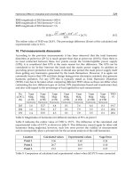
inspections. Fig. 5 presents characteristic gray tone distribution curves for dif-
ferent surfaces. Fig. 5 clearly shows the various curves for differently corroded
Fig.5. Image of acorrodedconcrete surfacewithsuperimposedgrayscale curve
forsubareas.
surfaces.Clearly, differentlydamagedsubareas canbeidentified individually.
The totalassessmentofpotential corrosionwould be obtained by averaging
theentireimage space.
In addition, laserscanners,whichmeasure thecrosssectionofthe pipe,
are used to detect corrosionwithanaccuracyof ± 4mm.
4.2Obstacles,Sediments, Incrustations, Mechanical Corrosion
Newly developedultrasound scanners withanaccuracyofmeasurement of
± 2mmare being used to detect obstacles,depositsand mechanicalerosionin
thewater space.
Fig. 6shows thetestsetup forgeometrymeasurement in thewater spacewith
ultrasound scanners andascan image.
4.3Crack DetectioninConcretePipe
First, digital image processing systemsare used to detect cracks in thegas
space. Several cameras are used to identify cracks in thegas space.
Automated Inspection System for Large Underground Concrete Pipes 575
Fig.6. Geometry measurements with ultrasound scanner(obstacles, sediments)
In accordance with the requirements, cracks with a width of 0.5mm and up-
ward have been positively identified and logged. While cracks can reach a
long length, their frequently very narrow width makes great demands on the
measuring system mapping them. Other measures such as comparisons with
previous inspections and images of other cracks with known width as well
as the superimposition of scales help make it possible to more closely de-
termine crack width and thus more closely detect the type of damage. An
important analysis module is automatic crack detection. It employs methods
of image processing and pattern recognition in order to determine whether one
or more cracks are possibly visible on a particular image or not. Particularly
when there are small cracks, which an operator could overlook on the moni-
tor, this automatic system constitutes a considerable advantage and increases
the quality of the inspection results. Fig. 7 illustrates how different analysis
modules identified a crack. In addition, each crack was graphically marked as
a recognized structure for the purpose of presentation. The entire crack con-
figuration was never identified. However, only the information of whether a
Fig.7. Details of result images when different crack detection methodsare employed
576 N. Elkmann et al.
crack may be present in a particular image or not is important for supporting
the user. It follows from this that the automatic analysis module can already
terminate the processing of the current image and inform the user once any
crack segment has been found.
Additionally, new acoustic methods (ultrasound, impact-echo) have been
developed or adopted to detect cracks in the concrete in the gas and the water
space. These acoustic systems are able to provide information on crack depth.
The acoustic methods for crack detection additionally allow the following:
• With the right sensor system, cracks can be detected in the water space
too.
• Cracks can be roughly classified (crack depth).
• Spallings can be detected and wall thickness can be determined.
Fig.8. Acoustic sensor systemsfor crack detection
The use of these sensors sensor systems for crack inspection is completely new.
4.4 Deviation of Pipe Position
Horizontal and vertical deviations of position and joint gaps have to be mea-
sured. Laser scanners, aligned laterally or on the apex of the sewer, are used
to detect and record the horizontal and vertical deviations of position.
In the gas space, cameras measure the joint gap. Differences in joint width
compared with earlier inspections indicate an axial displacement. Inconstant
joint width along the pipe circumference indicates a deformation.
Automatic measurement requires exact identification of the joint edges. To
this end, image processing methods (segmentation, contour-finding) determine
the pixels on the edges of the joint.
Fig. 9 (a) shows a detail of the identified pixels. When the parameters have
been suitably selected, the joint edges can be identified with an accuracy of
a few pixels. If these pixels are used to apply ellipse approximations, which
optimally approximate the number of points, the joint edges are obtained,
which support automatic measurement of the joints.
Automated Inspection System for Large Underground Concrete Pipes 577
Fig. 9 (b) shows a detail of the joint image with such ellipse approximations.
A Hough transformation can be used to determine the ellipse approxi-
mations. Since positioning and joint identification already identify the joint
edges, the parameters of the corresponding ellipses are also approximately
known. Thus, the search area of the Hough transformation can be restricted
greatly, making efficient implementation possible.
Fig.9. Image detail with detected jointedges:Whenmeasurementismanualthe
jointwidth canbemarkedbyhand(a).Whenjointmeasurementisautomated,
ellipse approximationsare placed throughthe jointedges (b).
5Summary andOutlook
Since2002, theFraunhoferIFF as general contractorhas developedacom-
prehensive conceptfor inspectionand cleaning systemsfor theEmscher sewer
system.Not only have allthe relevantsubsystemsbeen identifiedbut they
have also been designed in detail andsubjected to allnecessary testsinorder
to be able to provide reliable informationabout their feasibility. Feasibility
wasfullydemonstrated.Fociofdevelopmentwerethe carrier systemsfor
movement alongthe sewerline guaranteeingmaximum recovery certainty,the
pipeaxismeasurement andpositionsensing of thesystemsinthe sewerand
thesensorsystemsfor detectingthe conditionofthe sewer’sgas andwater
spaces.Differentsensorsystemshavebeen developedand tested in thetest
stationaswell as in arealsewer.Erosion, incrustationsand corrosionofcon-
creteare detected with great accuracy. Cameras detect axialdisplacement and
laserscanners detect offsets in pipejointsinthe gas space. Apart from the
cameras,differentsensors forcrackdetectioninthe gas andwater spacewere
developedonanacousticbasis (e.g.ultrasound).
578 N. Elkmann et al.
Along with the sensors, all systems were designed for the favored inspection
and cleaning concept. This involved a system for rough inspection of the
sewer (Spy) as well as cleaning systems and inspection systems. The control,
the operation, the introduction into and extraction from the sewer and the
manhole as well as the energy and water supply were engineered and the
certainty of recovery in case of breakdown was guaranteed.
In consultation with the Emschergenossenschaft, the Fraunhofer IFF de-
veloped and built a prototype of the spy and test prototypes of the cleaning
system and the inspection system in order to acquire more experience un-
der real conditions in the sewer. The swimming behavior of the Spy and the
floating test prototype for the inspection system were studied. The sensor
behavior for crack detection and sewer cross section measurement was also
tested. The collected findings and insights will now enter into the engineering
and development for final prototypes.
The feasibility of automatic inspection and cleaning systems for the Em-
scher sewer system and the fulfillment of the legal requirements for inspection
and cleaning have been demonstrated. The research on and tests of the in-
spection systems, the sensor systems and the cleaning technology guarantee
the inspection and cleaning required by law in a one-pipe sewer.
References
1. Hertzberg, Christaller,Kirchner, Licht, Rome:”SewerRobotics”, In: Proc.
From Animals to Animats 5, 5thIntl. Conf.OnSimulation of Adaptive Behav-
ior (SAB-98),R.Pfeifer andB.Blumbergand J A. Meyerand S.W. Wilson
(eds), MITPress, P. 427-436, 1998
2. Kuntze H B., Haffner H.:Experiences with theDevelopment of aRobot for
SmartMultisensoric PipeInspection.ICRA1998: 1773-1778
3. Rome E., HertzbergJ.,KirchnerF., LichtU., StreichS., Christaller Th.: To-
wardsAutonomousSewer Robots:the MAKROProject UrbanWater 1, 1999,
P. 57-40
4. KirkhamR:, Kearney, P. Rogers K. andMashford J.:PIRAT -ASystemfor
Quantitative SewerPipeAssessment. International JournalofRoboticsRe-
search,Vol. 19, No.11, November 2000
5. Elkmann N.,AlthoffH., SaenzJ., B¨ohme T.:KinematicsSystems forInspection
andCleaningofSewer Canals. 6thInternational Conference on Climbing and
WalkingRobotsCLAWAR, Catania, 2003
6. Elkmann N.,AlthoffH., B¨ohme T.,FelschT., KutznerS., SaenzJ., St¨ urze
T.:Entwicklung vonRobotersystemen f¨ur dieInspektion undReinigung von
Abwasserkan¨a len, Robotik2004, M¨unchen, 17–18 June 2004
7. Elkmann N.,AlthoffH.: Theemscher:kanal -Development of an Automated
Inspection Systemfor Underground Concrete Pipes,22thInternational NO
DIG Conference,15.–17. November 2004, Hamburg, Germany
An Autonomous Weeding Robot
for Organic Farming
Tijmen Bakker
1
, Kees van Asselt
1
, Jan Bontsema
2
, Joachim M¨uller
3
and
Gerrit van Straten
1
1
Wageningen University, Systems and Control Group, P.O. Box 17, 6700 AA
Wageningen, The Netherlands,
2
Agrotechnology and Fo od Innovations BV, P.O. Box 17, 6700 AA Wageningen,
The Netherlands
3
University of Hohenheim, Institute for Agricultural Engineering, 70593
Stuttgart, Germany
Summary. The objective of this research is the replacement of hand weeding in
organic farming by a device working autonomously at field level. The autonomous
weeding robot was designed using a structured design approach, giving a good
overview of the total design. A vehicle was developed with a diesel engine, hydraulic
transmission, four-wheel drive and four-wheel steering. The available power and the
stability of the vehicle does not limit the freedom of research regarding solutions for
intra-row weed detection and weeding actuators. To fulfill the function of navigation
along the row a new machine vision algorithm was developed. A test in sugar beet
in a greenhouse showed that the algorithm was able to find the crop row with an
average error of less than 25 mm. The vehicle is a versatile design for an autonomous
weeding robot in a research context. The result of the design has good potential for
autonomous weeding in the near future.
Keywords: Systematic design, machine vision, GPS, robotics, intra-row
weed control, autonomous weeding robot, organic farming
1Introduction
Weeds in agricultural production are mainly controlled by herbicides. As in
organic farming no herbicides can be used, weed control is amajor problem.
Whilet
here
is
sufficien
te
quipment
av
ail
ablet
oc
on
trol
thew
eeds
in
be
twe
en
the rows, weed control in the rows (intra-rowweeding) stillrequires alot of
manual labour.This is especially the case for crops that are slowly growing
and shallowly sown likesugarbeet, carrots and onions. In 1998, on average
73 hours perhectare sugar beet were spentonhand weeding in the Nether-
lands
[4].
The
required
lab
our
for
hand
we
eding
is
exp
ensiv
ea
nd
often
not
P. Corke and S. Sukkarieh (Eds.): Field and Service Robotics, STAR 25, pp. 579–590, 2006.
© Springer-Verlag Berlin Heidelberg 2006
580 T. Bakker et al.
available. An autonomous weeding robot replacing this labour, could mean
an enormous stimulus for organic farming. This paper presents the design of
such an autonomous weeding robot currently being developed at Wageningen
University.
2 The Design Procedure
2.1 Method
The autonomous weeding robot is designed using a phase model as the design
method[3]. In this phase model the design of a product is represented as a
process consisting of a problem definition phase, alternatives definition phase
and a forming phase (figure 1). The results of the different phases are solutions
on different levels of abstraction.
The problem definition phase starts with defining the objective of the design.
In the problem definition phase also the set of requirements is established.
The requirements can be split into fixed and variable requirements. A design
that does not satisfy the fixed requirements is rejected. Variable requirements
have to be fulfilled to a certain extent. To what extent these requirements are
fulfilled, determines the quality of the design. The variable requirements are
also used as criteria for the evaluation of possible concept solutions. The last
part of the problem definition phase consists of the definition of the functions
of the robot. A function is an action that has to be performed by the robot to
reach a specific goal. In our case, important functions are ’intra-row weeding’
and ’navigate along the row’. The functions are grouped in a function struc-
ture, which represents a solution on the first level of abstraction.
The function structure consists of several functions. Every function can be
accomplished by several alternative principles, e.g. mechanical and thermal
principles for weed removal. In the alternatives definition phase, possible al-
ternative principles for the various functions are presented in a morphological
chart (fig. 3). The left column lists the functions and the rows display the
Fig. 1. Thedesign process
An Autonomous Weeding Robot for Organic Farming 581
alternative principles. By selecting one alternative for each function and by
combining these alternatives, concept solutions can be established. These con-
cept solutions are represented by lines drawn in the morphological chart. The
best concept solution can be selected using a rating procedure. In the forming
phase this selected concept solution is worked out into a prototype.
2.2 Application for the Weeding Robot
The objective of the research is formulated as ’replacement of hand weeding in
organic farming by a device working autonomously at field level’. Starting from
this objective, the first step in the problem definition phase was to establish
the set of requirements. For this purpose interviews were held with potential
users, scientists and consultants related to organic farming. The resulting
requirements are as follows:
Fixed requirements:
• Replacing hand weeding in organic farming.
• Applicable in combination with other weed control measures.
• Manual control of the vehicle must be possible for moving the vehicle over
short distances.
• Weeding a field autonomously.
• Ability to work both day and night.
• The weeding robot should not cross the field boundaries.
• The weeding robot must be self restarting in absence of emergency.
Fig. 2. The function structure
582 T. Bakker et al.
• The weeding robot informs the farmer when the weeding robot stopped
definitely (e.g. due to security reasons) or when it is ready.
• The weeding robot sends its operational status to the user at request
• The weeding robot must function properly in sugar beet.
Variable requirements:
• Removing more than 90 percent of the weeds in the row.
• The costs per hectare may be at least comparable to the costs of hand
weeding.
• Damage to the crop is as low as possible.
• The soil pressure under the weeding robot must be comparable or less than
for hand weeding.
• Energy efficient.
• Safe for people, animals and property.
• Suitable as research platform.
• Limited noise production
• Reliable functioning.
• Easy to use.
After establishing the set of requirements the functions of the the weeding
robot were identified. These functions were grouped into a function block
scheme. This scheme is represented in figure 2. The lines in the scheme in-
dicate flows of energy, material or information. Functions located in parallel
lines can be performed simultaneously.
The navigation system consists of four functions. Firstly, the weeding robot
should constantly determine if it is located in- or outside the field. Secondly,
if within the field, it should determine if it is on one of the headlands or not.
Thirdly, in case it is not on the headlands, it should navigate along the row
and perform the intra-row weeding. Fourthly, if the weeding robot arrives on
the headland, it should stop the intra-row weeding and start to navigate to
the next crop rows to be weeded. This sequence repeats until the whole field,
except the headlands, is weeded. Weeding of the headlands is left out of con-
sideration. An increasing number of farmers in the Netherlands do not grow
sugar beet at the headlands because they think it is not cost-effective.
In the alternatives definition phase possible alternative principles for the vari-
ous functions are listed in a morphological chart (fig. 3). Four people involved
in the project drew lines indicating possible concept solutions in the chart.
These concept solutions were then weighed against each other using the vari-
able requirements listed before. The concept solution indicated by the line in
figure 3 is the final concept solution.
In the forming phase described in section 3 the concept solution was worked
out into a prototype.
Fig.
3.
Morphologicc
hart
An Autonomous Weeding Robot for Organic Farming 583
584 T. Bakker et al.
2.3 Results of the Design Process
Determine where intra-row weeding has to be performed
To determine where intra-row weeding has to be performed, pattern recog-
nition of plant locations is going to be used. From earlier research [2] it is
expected that the quality of detection of this method is at least as good as
the quality of detection of other methods. Though combinations of methods
like recognition of pattern, shape and colour are expected to have a potential
for higher quality of detection, just pattern recognition is chosen because it is
expected to be sufficient.
Positioning of weeding
To position the actuator at the location indicated by the detection system
dead reckoning is going to be used. A wheel with encoder, giving a precise
distance measurement, will be available already because it is also needed for
the pattern recognition system.
Intra-row weeding
Intra-row weeding will be performed by a mechanical actuator. It is expected
to be difficult to remove weeds growing close to a crop plant by air, flaming,
electricity, hot water, freezing, microwaves or infrared without damaging the
crop plants. In that respect laser would be an excellent solution. However,
laser can not work under the ground surface, and has therefore less effect on
certain weed species. On the other hand, not moving the soil prevents buried
seeds from germinating. A greater disadvantage of laser is its high price. High
power laser is needed to reach reasonable performance, and this involves high
costs. Water-jet could also probably be a good solution for intra-row weeding,
but this needs much more investigation than a mechanical solution.
Determine if within field
GPS is selected to determine wether the weeding robot is within the field or
not. The determination if the weeding robot is located within the field or not,
needs to be guaranteed correctly at any time. A combination of vision and
dead reckoning can not give this guarantee as good as a solution in which
GPS is used. Dead reckoning could improve the position determination by
GPS. However, if a GPS is selected with sufficient accuracy, additional dead
reckoning is not needed.
Navigate along the row
Machine vision is selected for navigation along the row. Machine vision makes
it possible to navigate along the row by relative positioning to the row. There-
fore the weeding robot can work in any field without requiring absolute co-
ordinates of a path to be followed. Absolute positioning by means of GPS,
possibly combined with other sensors, requires knowledge of the absolute po-
sition of crop rows in a field. Navigation along the row by relative positioning
to the row could be done also using tactile, ultrasonic or optical sensors com-
bined with dead reckoning. Tactile sensors are not going to be used because
in case of sugar beet they could harm the crop. Machine vision is preferred
over ultrasonic or optical sensors, because of the ability to look forward, which
contributes to a more accurate control of the position of the weeding robot rel-
ative to the crop row. It is not clear wether dead reckoning could substantially
contribute to the navigation accuracy feasible with machine vision.
Determine if on headland
GPS is selected to determine if the weeding robot is located on the headland.
Using GPS requires some labour for recording the border of the headlands in
advance, but will result in a correct headland detection. If a high accuracy
GPS is selected, accuracy does not have to be improved by dead reckoning.
Tactile, ultrasonic or optical sensors in combination with dead reckoning could
also be used to determine wether the robot is on the headland, by detecting
the end of the row, i.e. if over some predefined distance no row is detected.
However, another crop may grow on the headland (seeded to prevent germi-
nating of weeds) or crop rows seeded at the headland can cross the crop row
to be followed. In these situations the latter solutions can not guarantee a
correct detection of the end of row, and therefore also not a correct head-
land detection. Machine vision could give more reliable results, but it is still
difficult because headland to be detected is not so structured.
Navigate on headland
For navigation on the headland GPS is selected. On the headland the weeding
robot has to make a turn and position itself in front of the next rows to be
weeded. At the moment the robot arrives at the headland, a virtual path is
planned to a position in front of the next rows to be weeded. Navigating over
this path is going to be done by GPS.
Locomotion related functions
A diesel engine with a hydraulic transmission was selected for the locomo-
tion related functions. For weeding quite some power could be required and
the available power should not be limiting for realizing the objective of au-
tonomous weeding of a field. A diesel engine with an hydraulic transmission
is a proven concept in agriculture. A gearbox limits the possible combinations
of the number of engine revolutions and driving speed and shuffling is difficult
to automate. A continuously variable or hydraulic transmission is therefore
preferred over a gearbox. Hydraulics makes it possible to design a compact
wheel construction preventing damage to the crop.
A design with four wheels is preferred over one with three because of stability.
An Autonomous Weeding Robot for Organic Farming 585
586 T. Bakker et al.
It was decided that four wheels is also preferred over two or four tracks. The
most important advantages of tracks in practice are the better traction and
the less soil compaction. But it is expected that if four wheels are used for
such a light-weight vehicle (not more than 1500 kg) soil compaction will be ac-
ceptable. Traction when using wheels is expected to be good enough because
of the limited weight and the limited need of traction for intra-row weeding.
Four wheel drive and four wheel steering were chosen to have the possibility
to investigate all kinds of driving strategies.
Communication with the user
Specific settings for a field will be defined by a board computer. Any moment
a user wants to know the status of the weeding robot, the weeding robot
status will be accessible via the internet. A website gives good opportunities
to represent information in an orderly way and it is easily accessible from
everywhere. In case the weeding robot needs help from its user, the weeding
robot notifies its user by sending an SMS (Short Message Service) message by
the GSM network. In the Netherlands any place is covered by the GSM net-
work. From the alternatives listed, SMS is the solution that gives the highest
assurance that the user really receives the message shortly after it is sent.
Detect unsafe situations
Detecting unsafe situations will be done super canopy all around the weeding
robot. Situations in which this solution is not sufficient are hardly imaginable.
Ideally the weeding robot should detect every unsafe situation, at every level
and direction. Even if somebody is lying in between the crop rows below
canopy level this should be detected. Because of the research effort involved
in reaching the ideal objective mentioned and the possible high costs for such
a solution, detecting around and only super canopy is preferred.
3 The Vehicle
The size of the vehicle was determined by the standard track width used in
agriculture in the Netherlands which is 1.50 m. This track width also makes
the design versatile in the sense that it is suitable for crops grown in beds like
carrots an onions. See figure 4 for the resulting vehicle.
Sugar beets are grown at a row distance of 50 cm so the weeding robot cov-
ers three rows. The engine power is selected so that it has enough power for
driving and steering under field conditions and for driving three actuators.
The required power for the actuators was calculated based on an actuator
specially designed for intra-row weeding by Bontsema et al. [2]. The engine is
a 31.3 kW Kubota V1505-T.
The ground clearance is about 50 cm to prevent the crop from being damaged
by the vehicle. The vehicle is 2.5 m. long to have enough space for mounting
Fig. 4. Theweeding robot
actuators under thevehicleinthe middle between the frontand rear wheels.
The tyre width of 16 cm leavesenoughspace for steering in between crop rows
while
soil
compaction
is
exp
ected
to
be
acceptable.
The
we
igh
to
ft
he
ve
hicle
is about 1250 kg.
The engine drives two hydraulic pumps. One supplies the oil for steering and
driving,
and
the
other
for
driving
the
actuators.
The
oil
for
driving
and
steer-
ing flows to aelectrically controllable valveblock witheightsections. Four
are used for steering and four are used for controlling wheel speed, so wheel
sp
eeds
and
wheel
angles
can
be
con
trolled
individually
.T
he
wheels
are
driv
en
by radialpiston motors.The required driving speed rangefor intra-rowweed-
ing is 0.025 m/s -2m/s continuallyvariable. Adesired top speed of 5.6 m/s
wa
ss
pe
cified
for
fast
mo
ving
of
the
rob
ot
withinafi
eld.
It
app
eared
that
hydraulics could not be designed to have avariablework speed from 0.025
m/s to 5.6 m/s. Asolution wasfoundbydesigning the hydraulics so that
two
sp
eed
ranges
exist.T
he
wo
rking
sp
eed
ranges
up
to
3.2
m/s.
Am
aximu
m
travelspeed of 6.4 m/s is realized by changing to twowheel drivebycombin-
ingthe oil flows of four wheels into twoflows.
Eac
hw
heel
is
steered
by
an
hy
draulic
motor
with
ar
eduction
gear.
The
max-
imum steeringspeed is 360 degrees persecond. The angles of the wheels are
measured by anglesensors. The oil for driving the wheels flows via aturnable
oil throughput. This makes it possible to turn the wheels in anyangle from
0-360
degrees.
The weeding robot electronics consists of 6units connected by aCAN bus
An Autonomous Weeding Robot for Organic Farming 587
588 T. Bakker et al.
Fig. 5. Electronicsarchitecture
using the ISO 11783protocol. In figure 5anschematic overview is given of
this system with vehicle control related sensors and valves. Four micro con-
trollers are located near the four wheels to measure the wheel speed and the
wheel angle. Angles, wheel speeds and wheel direction are transmitted using
the CAN bus. Via the CAN bus and two other microcontrollersthe hydraulic
va
lv
eb
lo
ck
is
cont
rolled.
One
laptopp
ro
cessesi
mages
supplied
by
the
camera
connected and returns the location of the crop rows in relation to the vehicle
position in aCAN busmessage. Another laptop does the vehicle control. It
gathers wheel speed, wheel direction, crop rowlocation dataand GPS data
and
con
trols
the
ve
hicle
by
sending
messages
to
the
unitsc
onnected
to
the
valveblock.This laptop is also the user interface of the weeding robot. Are-
mote control is connected to this laptop via aradiomodem for manual control
of
the
we
eding
rob
ot.
Besides
the
sensors
directly
related
to
na
vigation
and
control, there are some more sensors connected to the modules. These sensors
indicate oil filtersfunctioning, oil temperature and oil level are also interfaced
to the laptop. If asensor indicates an emergency,the weeding robot will turn
off automatically.
4 Navigation Along the Row
As explained in section 2.2 part of the navigation system of the weeding robot
will consist of navigating along the row using machine vision. The machine
vision algorithm was developed and tested on a sugar beet field prepared in a
greenhouse. The area covered by one image was 2.5 meters long in row direc-
tion and 1.5 meters wide at the side closest to the camera. This means that
three complete rows are visible in the image. The first step in the row recog-
nition algorithm, is transforming the RGB image to a grey scale image with
enhanced contrast between green plants and soil background. The next step
is to correct the images for perspective by an inverse perspective transforma-
tion. In the corrected image three rectangular sections of crop row spacing are
selected. The first section is selected in the middle of the image. The other
two are selected on both sides of the first section. The sections are combined
by summing up the grey values of the sections to a combined image. To the
AB
C
Fig. 6. Typical images together with estimatedrow position at differentgrowth
stage andweed pressure
resulting combined image grey scaleHough transform is applied.
Measurementsshowthat the algorithm is able to find the rowindependent
of
thec
rop
stage.
Fu
rthermore,
the
algorithm
has
found
the
crop
ro
wi
ni
m-
ages with ahigh weed density. Some typical results can be found in figure 6.
The qualityofthe rowposition estimation is determined by comparing the
lines
found
by
the
algorithm
with
lines
po
sitioned
ove
rt
he
crop
ro
ws
by
hand
in the originalimage. The averagedeviation between the estimated and real
crop rowvaried from 6to223 mm. The higher deviationsinthis rangecan be
explained
by
the
nu
mb
er
of
plan
ts
visible
in
early
crop
stage,
ove
rexp
osure
of
the camera, and the presenceofalot of green algae due to ourexperimental
setup.Ignoringthe measurements under these extreme conditions, the algo-
rithm
wa
sa
ble
to
find
the
ro
ww
ith
an
ave
ragee
rror
of
less
then
25
mm.
The measured processing time varied from 1to1.5 seconds perimage. This
variation can be explained by the varying amountofweed. The more lightpix-
els
there
are,t
he
more
pixels
ha
ve
to
be
pro
cessed
by
the
Hought
ransform.
Details can be found in [1].
5C
onclusions
The advantage of using astructured design procedure is thatitprovides a
go
od
ove
rview
of
the
complete
design.
Also,t
he
design
metho
df
orces
the
designer to look at alternativesolutions. Because of thestructured sequence
of design activities,itiseasy to keep trackofthe progressofdesign. In a
researchcontext it is easy to identify alternativesubjects that are worthwhile
to
in
ve
stigate
further.
But
in
the
mean
time
the
main
line
of
the
researc
h
remains clear.
An Autonomous Weeding Robot for Organic Farming 589
590 T. Bakker et al.
Applying the design procedure for the autonomous weeding robot resulted in
a flexible research vehicle. The design consisting of diesel engine, hydraulic
transmission, four wheel drive and 360 degrees four wheel steering is a good
concept for an autonomous weeding robot in a research context. The available
power and the stability of the vehicle does not limit the freedom regarding
research to solutions for intra-row weed detection and weeding actuators.
From the established functions only for navigation along the row a new algo-
rithm to detect sugar beet rows is discussed. The algorithm is able to find the
row with an average error of less than 25 mm. Processing one image cover-
ing 2.5 meters row length takes less than 1.5 second. It is not expected that
the attainable driving speed of about 1.5 m/s will be limiting. From earlier
research it is expected that the actuator will limit the driving speed to 1 m/s
or less. So it can be concluded that the results of the algorithm give good
perspectives to navigate an autonomous vehicle along rows in a sugar beet
field.
The planning for the current year is to finish the autonomous navigation
and control of the weeding robot. This will be tested in a sugar beet field.
Adding an intra-row weeding system is planned for next year. The ultimate
test will then be to show that it is possible to weed a whole sugar beet field
autonomously by a weeding robot.
References
[1]
T. Bakker, H. Wouters, C.J. vanAsselt, J. Bontsema, J. M¨uller, G. van
Straten, and L. Tang. Avisionbased rowdetection system for sugar
be
et.
In
Computer-Bildanalysei
nd
er
La
ndwirtschaft.
Workshop
2004,
Bornimer Agrartechnische Berichte, pages 42–55, Braunschweig, Germany,
2004. Institutf¨u rAgrartechnik Bornim e.V.
[2]
J.
Bon
tsema,
C.J.
va
nA
sselt,
P.
W.J.
Lemp
ens,
and
G.
va
nS
traten.
In
tra-
rowweed control: amechatronics approach. In 1st IFAC Workshopon
ControlApplications and Ergonomics in Agriculture ,pages 93–97, Athens,
Greece,
1998.
[3]
H.H.van den Kroonenberg and F.J. Siers. Methodisch ontwerpen.
Ontwerpmethoden, voorbeelden,cases,oefeningen.EducatievePartners
Nederland
BV,
Houten,
1998.
[4]
R.Y. vander Weide, L.A.P.Lotz,P.O. Bleeker, and R.M.W. Groeneveld.
Het spanningsveld tussen beheren en beheersen vanonkruiden op biologis-
chebedrijven. In F.G. Wijnands, J.J.Schroder, W. Sukkel, and R. Booij,
editors, Themaboek303. Biologisch bedrijf onder de loep,pages 129–138.
Wageningen Universiteit, Wageningen,2002.
VShape Path Generation for Loading
Op
eration
by
Wheel
Loader
Shigeru Sarata
1
,Yossewee Weeramhaeng
2
,Akira Horiguchi
3
,and
Takashi Tsubouchi
2
1
AIST, Namiki1-2-1,Tsukuba, Ibaraki, JAPAN
2
UniversityofTsukuba, Ten-nohdai 1-1-1, Tsukuba, Ibaraki, JAPAN
3
Sogo SecurityService Co., Saitama, JAPAN
Summary. In this paper, as apart of researchwork on the autonomous loading
operation by wheel loader at surface mines or construction working places, ame-
thodofpath generation for wheel loader will be described. Vshapepath connecting
between the scooping position and the loading position consistsofclothoid curves
and straightlines. Eachlength of line segments are optimized in path generation
pro
cedure.
The
sco
oping
direction
is
determined
based
on
the
estimation
of
re-
sistanceforce applied on the bucketduring scooping motion, by using simplified
shapemodel of pile and buckettrajectory model. Proposed methodisinstalled on
the experimental model. Shapeofthe pile is measured by astereo-vision system. For
giving scooping position, scooping direction giving the least momentonthe bucket
is
selected.
By
this
metho
d,
appropriate
path
is
generated.
Keyw
ords:
Pa
th
generation,
wheell
oader,
loading
op
eration,
sco
oping
1Introduction
One of themajor fields forintelligentsystem applications is field of miningand
construction. The working environment in mining or construction consists of
irregular shaped material suchasfragmented rock,sandorsoil,and changes
itsshape with advancing the operation. Unmanned systems in these fields
should be intelligentsystems that can decideits actions based on the changing
situation. Wheel loader (FrontEnd Loader:”loader”hereinafter) is used for
loadingmaterials widelyinthesefields. It has largebucketatfront end and
four wheels. The main functions of the vehicle aretoscoop with the bucket
andfreely maneuver with the wheels(Fig. 1). Our group has been researching
an
autonomoussystem for the loadingoperation of this vehicle [1,2]. A
methodofpath-generation forwheelloadersaspartofour ongoingresearchis
describedinthis paper. Severalresearches have been conducted on automatic
operationsystem of wheel loader [3, 4]. These developed systems employeda
guidance method or ateaching-playbackmethodfor traveling. Path generation
P. Corke and S. Sukkarieh (Eds.): Field and Service Robotics, STAR 25, pp. 591–602, 2006.
© Springer-Verlag Berlin Heidelberg 2006
592 S. Sarata et al.
Fig.1
.
Wheel
Loader
Pile
Loader
DumpTr
uck
Fig.2. VShapePath
functionwas notincluded. As mentioned previously,path planning is oneof
the essential functions for autonomous operationsystem.
In the most commonloadingoperation,loader travels on Vshape path
between scooping pointand loadingpointonadump truckincluding aswitch
back pointasshown in Fig. 2. This paperdescribes amethodtodeterminethe
scooping directionbasedonthe shape of thepile and amethodtogenerate
Vshape path. The proposed methods are applied in an experimental model
and evaluated.
2P
ath
Planning
2.1 Steering System of Wheel Loader
Steering mechanismofwheelloader is articulatesteeringsystem as shown in
Fig. 3. The body of theloader is separatedintoafront part andrear part
connected by acentre pin.The angle around the centre pin is controlled by
hydrauliccylinders. Because distances from centre pin to frontaxel and to
rear axel are same, frontwheels andrear wheels runonsame trace andwheel
loader has high mobilityinoffroad such as muddy or softsoil.
R
L
φ
Fig.3. Steering Mechanism