Autonomous Robotic Systems - Anibal T. de Almeida and Oussama Khatib (Eds) Part 8 doc
Bạn đang xem bản rút gọn của tài liệu. Xem và tải ngay bản đầy đủ của tài liệu tại đây (1.07 MB, 20 trang )
135
evolution in the context of the environment. The component unit of social system
does not have to be a biological agent. There can be a social system composed of
artificial autonomous agents, that is a robot society.
i ~-~ Self-Organization ~ ~ ]
I /~/ I
L__ _I~
I F~ Self-Organization ~ ]
Fig.6 Coupling Structure of Self-Organizing Mechanism
4.2. Designing Social Group Behavior
4.2.1 Basic model description
Let us consider a minimum level organization network of resource mining task, as
shown in fig.7-(a). The model represents the relation of functioning processes of
robot society, that is, resource mining, resource and energy transportation, and parts
assembling sites. The symbols used in fig.7 are defined in table 1. In this model,
energy is supplied from environment to the site ET, and the energy is distributed to
site P and R through path T1 and T3 respectively by the robots. At site R, robots
execute resource mining task. The resource is transported to and consumed at site P
or RC for the parts assembling and energy conversion. The converted energy at RC
can be carried to ET for energy supplement. Environmental constraints to the system
are twofold; constant energy supply from site ET and request of part production at
site P. Parts are constantly removed from P. If too many robots work for parts
production, the labor power to energy supply and resource mining decrease and this
results in low performance of the system.
Energy Input Parts Output
Energy from Resource Resource mining
(a) Functional Network for Resource Mining (b)
Energy
Flmv Network
[] M
(d) Resource Flow Network
Fig.7 Organization network structure for respective information currency
136
Thus, this network system requires task differentiation of a number of robots and
self-coordination of internal population balance for respective task. Unlike
conventional work of group robotics, robots in this model do not share common
goal because desired condition at respective site is different from each other. The
purpose of behavior for each robot is generated through internal observation of
respective site.
4.2 Multi-layer Network Expression
Observation of the network structure is a projection based on particular criteria
which are focused on. Hence, we are concerned with population, energy and resource
flow in our model. Without saying, each robot behaves based on the local
information of locating site and its neighbor condition, the spatial distribution of the
population, which implies labor distribution in the network, evolves in the self-
organizing manner. However, it should be noted that this self-organizing labor
distribution depends on energy and resource distribution of the network. As well as
quantitative amount, spatial distribution of energy and resource affects structure
organization of population. On the other hand, since robots transport energy and
resource from site to site, the distribution of energy and resource change based on
population network. Thus, spatial distributions of energy, population and resource
are closely coupled. Figure 8 represents the conception of this relation. In our
model, fig.7-(b), (c), and (d) represent energy flow network (EFN), population flow
network (PFN), and resource flow network(RFN), as a projection of the structure
fig.4-(a).
Table 1 Role of the site
Energy Tank site ET
P Parts assembling site
R Resource mining site
RC Resource to energy conversion site
Tx Transportation paths (x=l to 5)
}
Energy
Flow
Fig.8 Interdependence of network structure
4. 2.3 Nonequilibrium and Purpose generation
In general, the robot works so that a purpose is achieved. However, this model dose
not prepare a priori defined purpose for the robots. The task and purpose for each
robot are determined in a context of situation. There is an even the case that some
137
robots do nothing. The only thing what robots do is to reduce the difference between
the current state and desired state. Task selection of the robot depends on the site
where the robot is currently located. For example, if the robot is located in the site
P, and it recognizes shortage of the resource for parts assembling despite energy
amount is satisfied, it heads to the site R via route T4 to supply resource to the site
P. The recognition of the difference of state condition is performed based on
eq.(4.3.1), and which is a driving force of purpose generation. Robots recognize
amount of energy and resource of the neighboring sites, and decide next task type
with eq.(4.3.2), which are given by,
P~ = {(O xi - xc)2 iff xi > Xc
(4.3.I)
A/'tsT ={0 ~s-//T
iff #S>ll r
(4.3.2)
where p, denotes shortage from critical value
x c
of energy or resource at each site.
Also, A/Zs~ represents gradient of the nonequilibrium potential of energy or resource
amount between the sites. The decision of robot becomes different according to
current location of the robot. Every condition and task selections is situation
oriented. As is described in previous section, since energy and resource transportation
are carried out by the robots, structure of EFN and RFN is organized based on the
spatial pattern (structure) of PFN which denotes labor distribution on the network.
Thus, the pattern of PFN is a constraint condition of EFN and RFN's organizing
processes. On the other hand, since the labor distribution is reformed to facilitate
solution of the nonequilibrium state, the structure of EFN and RFN are constraints
conditions of reorganization of PFN structure as well. These networks are
impossible to divide each other and have meaning only in the context of inter
relation of the other network structures.
4.3 Simulation of Network Behavior
4.3.1 Structure configuration
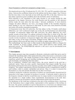
This section examines structure reorganization due to dynamical labor distribution.
Time average labor distribution (PFN) characterizes behavior of the network system.
If the energy supply is sufficient, labor power of the robot can concentrate to parts
assembling task without considering energy amount and produce as many amounts
of parts as required. PFN is organized such that parts production is maximized. On
the other hand, if the energy supply is not enough, some ratio of robots should be
devoted to the task related to energy conversion from the resource. This simulation
is performed to examine that network robot system behaves as expected according to
the energy supply. Population of the robot is 100. Other simulation setup values are
shown in table 3. As shown in fig.9-(a), in case that sufficient amount of energy is
supplied, most of the robots are afford to engage in the task related to the parts
assembling work. However, in the case of lack of energy supply, the energy
shortage at ET induces a nonequilibrium state at RC and a number of robots are
distributed to configure self-complimentary structure of energy network as shown in
fig.9-(b). More robots are engaged in energy transportation task rather than parts
production task in this case. Thus, the robots decide how to use resource according
to change of energy condition. It shows a characteristic of collective autonomy,
where the group behavior work to maintain activity of the system. A case of that
there are more choices as alternative conditions will be examined as a future work.
138
Table 2 Task type of robot ((*) denotes energy consumption
for a behavior, cf. tab.3)
1 Resource mining (m) 5 Energy explore (e)
2 Resource supply (e) 6 Assemble parts (b)
3 Resource explore (e) 7 Doing nothing (0)
4 Energy supply (e)
Table 3 Simulation setup value ([*] denotes unit of amount.)
1) total robot number N: 100
2) transportation step t IT]: 10.00
3) energy carrying/robot e [/]: 3.00
4) resource transportation r [k]: 1.00
5) energy consumption d [l]: 0.50
6) resource minin~ cost m Ill: 1.00
7) parts assembling cost b Ill: 2.00
8) resource exchange rate c [//k]: (8.0)
9) energy supply/time E [//T]: (3.00)
10) parts demand/time P [p]: 2.00
(a) (b)
(a) In case of Sufficient Energy Supply (E=10) (b) In case of Insufficient Energy
Supply (E=3) ( From left to right, bar denotes amount of energy, resource, and
population at each site.)
Fig. 9 Time average of Network Structure
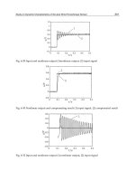
4.3.2 Diversity, Redundancy, and Optimality
When we consider what is a good system, we will find that the answer is situation
dependent. This section discusses the relation between diversity and optimality. To
show this, let us consider a network structure where the site R is disconnected to
RC as shown in fig. 10 (Type II). Hence, let us call the network structure of fig.7(a)
as type I and the one without RC as type II. With this network structure, fig. 1 t
shows the comparison result of the total parts production from the site P during
1000 time steps by changing energy supply E. The other setup values are the same
as the one as shown in table 3. In the fig. 11, production-opt denotes total output of
the network type II, while the others are results in case of type I. Both systems of
139
type I and type II require energy support to ET. When energy supply is sufficient,
type II network is more efficient in terms of productivity, because RC (energy
conversion) is a redundant part in this case. However, the performance of pazts
production is sharply affected to the energy supply. If energy supply is small, its
productivity is deteriorated. On the other hand, since type I network distributes some
pans of the labor powers for energy conversion task at RC even when the energy is
supplied sufficiently, type I cannot perform better than type II in case of enough
energy supply. Structure of Type I contains a redundant part (RC) in this case.
However in the case of energy shortage, RC site of the system takes an essential
role to maintain work ratio as shown in fig.12. In case of energy shortage, large
parts of robot are engaged in energy supply task{ T2,T3,R,T5,RC } rather than parts
production task. Thanks to this collective coordination, energy shortage is covered to
some degrees, and energy is utilized for executing parts assembling task as well as
maintaining the robot activity. Productivity in type I is better than that of type II in
case of energy shortage. It can be said that redundant pan is a vital component in
this case. So, these results show that there is a trade off between flexibility and
optimality. In general, optimization is to reduce redundancy form the system
performance, but it deprive potential ability of flexibility to dynamical change of
environment. Conventional systems are designed under assumption that necessary
conditions are always satisfied and only considered optimization of performance. But
this is not always guaranteed when we consider highly dynamical system, such as
the robot society. It should be firstly considered whether the system can maintain its
fundamental function when exposed dynamical change of environment.
1000
750
.~ 5oo
250
Type I Type II
0
0
• pro dlclion-opt
~m produ clion-c 10
1 2 3 4 5 6
Energy supply E
Fig. 11 Total parts production
during 1000 time
Fig. 10 Structure type of the Network
75
50
25
0 I ~ ~ ~' I work ~e-cl0
0 1 2 3 4 5 6
Energy ~apply E
Fig.12 Average work rate of
total population
5. Summary
In this paper, the issue of the cooperative behavior was discussed from local to
global coordination. For the local coordination, intentional cooperation is central
problem. As a basic technique for cooperation, this paper presented the information
140
sharing between heterogeneous agent and distributed sensing. On the other hand,
considering social robotics, we discussed how collective behavior should be
designed. The self-organizing collective behavior is fundamental for the global
coordination. There are several classes in self-organization. It should be more
rigorously discussed that which class of self-organization is fundamental for our
concerning system as a design principle, which may be different according to required
task and environment. Also, relation between flexibility and optimality of the
system performance are subtle problem, because these sometimes contradict with
each other. Flexible system is robust for dynamical environment, but not necessarily
optimal for specific task. How do we consider the balance of the system properties?
In this paper, two classes of cooperative behaviors were treated independently.
However, these are not separated problems each other. Local behavior cause a group
behavior, but it is influenced by the group behavior. We must consider the
coevolution between local interaction and group behavior. This is very interesting
and essential issue for social agent system. The competition between agents may be
also important to facilitate evolution. Our fundamental aim is to link these issues as
the general framework.
References
[1] Smith,Reid G. and Davis, R.,Framework for cooperation in Distributed Problem
Solving, IEEE Trans. Sys. Man. Cybem., SMC-11-1, 61-70, 1981.
[2] Fukuda, T., and Ueyama, T., Cellular Robotics and Micro Systems, World Scientific in
Robotics and Automated Systems-Vol.10, World Scientific, 1994.
[3] J. Wang and G. Beni, "Cellular Robotic Systems: Self-Organizing Robots and Kinetic
Pattern Generation", Proc. of IROS, pp.139-144, 1988.
[4] Noreils, Fabrice R. and de Nozay, Route, An Architecture for Cooperative and
Autonomous Mobile Robots, Proc. of International Conference on Robotics and
Automation, pp.2703-2710,1992.
[5] Parker, L., E., Multi-Robot Team Design for Real-World Applications, Distributed
Autonomous Robot Systems (DARS) 2, pp.91-102, 1996.
[6] Mataric, M. J., "Issues and Approaches in the Designing of Collective Autonomous
Agents," Robotics and Autonomous Systems, Vol. 16, 321-331, 1995.
[7] Marco Dorigo, Vittorio Maneiezzo, and Alberto Colorni, The Ant System:
Optimization by a colony of cooperative agents, IEEE Transactions on Systems, Man,
and Cybernetics-part B, Vol.26.'No.1, pp.l-13, 1996.
[8] Sekiyama, K. and Fukuda, T., Modeling and Controlling of Group Behavior on Self-
Organizing Principle, Proc. of IEEE International Conference on Robotics and
Automation,pp. 1407-1412, 1996.
[9] A. Cai, T. Fukuda and F. Arai, "Integration of Distributed Sensing Information in
DARS based on Evidential Reasoning", Proc. of 3rd International Symposium on
Distributed Autonomous Robotic Systems, pp.268-279, 1996.
[10] A. P. Dempster, A generalization of Bayesian inference, J.
Roy. Star. Soc., vol. 30,
pp. 205 ~ 247, 1968.
[11] G. Sharer, A Mathematical Theory of Evidence, Princeton, NJ: Princeton Uni. Press,
t976.
Mobile Manipulator Systems*
Oussama Khatib
Stanford University
Stanford, CA, 94305, USA
khatib~cs.stanford.edu
Abstract: Mobile manipulation capabilities are key to many new appli-
cations of robotics in space, underwater, construction, and service envi-
ronments. In these applications, consideration of vehicle/arm dynamics is
essential for robot coordination and control. This article discusses the in-
ertial properties of holonomic mobile manipulation systems and presents
the basic strategies developed for their dynamic coordination and control.
These strategies are based on extensions of the operational space formula-
tion, which provides the mathematical models for the description, analysis,
and control of robot dynamics with respect to the task behavior.
1. Introduction
A central issue in the development of mobile manipulation systems is vehi-
cle/arm coordination [1,2]. This area of research is relatively new. There is,
however, a large body of work that has been devoted to the study of motion
coordination in the context of kinematic redundancy. In recent years, these two
areas have begun to merge [3], and algorithms developed for redundant manipu-
lators are being extended to mobile manipulation systems. Typical approaches
to motion coordination of redundant systems rely on the use of pseudo- or gen-
eralized inverses to solve an under-constrained or degenerate system of linear
equations, while optimizing some given criterion. These algorithms are essen-
tially driven by kinematic considerations and the dynamic interaction between
the end-effector and the manipulator's internal motions are ignored.
Our approach to controlling redundant systems is based on two models: an
end-effector dynamic model obtained by projecting the mechanism dynamics
"into the operational space, and a dynamically consistent force/torque relation-
ship that provides decoupled control of joint motions in the null space associ-
ated with the redundant mechanism. These two models are the basis for the
dynamic coordination strategy we are implementing for the mobile platform.
Another important issue in mobile manipulation concerns cooperative op-
erations between multiple vehicle/arm systems. Our study of the dynamics of
parallel, multi robot structures reveals an important additive property. The
effective mass and inertia of a multi-robot system at some operational point
are shown to be given by the sum of the effective masses and inertias associated
with the object and each robot. Using this property, the multi-robot system
*presented at RoManSy'96, the llth CISM-IFToMM Symposium, Udine, Italy.
142
can be treated as a single
augmented object
[5] and controlled by the total op-
erational forces applied by the robots. The control of internal forces is based
on the
virtual linkage
[6] which characterizes internal forces.
2. Operational Space Dynamics
The joint space dynamics of a manipulator are described by
A(q)O+b(q,O) + g(q) = F;
(1)
where q is the n joint coordinates and A(q) is the n x n kinetic energy matrix.
b(q, Cl) is the vector of centrifugal and Coriolis joint-forces and g(q) is the
gravity joint-force vector. F is the vector of generalized joint-forces.
The operational space equations of motion of a manipulator are [4]
+p(x) = F; (2)
where x, is the vector of the m operational coordinates describing the position
and orientation of the effector, A(x) is the m x m kinetic energy matrix as-
sociated with the operational space. #(x, ~), p(x), and F are respectively the
centrifugal and Coriolis force vector, gravity force vector, and generalized force
vector acting in operational space.
3. Redundancy
The operational space equations of motion describe the dynamic response of a
manipulator to the application of an operational force F at the end effector.
For non-redundant manipulators, the relationship between operational forces,
F, and joint forces, r is
r = jT(q)F; (3)
where J(q) is the Jacobian matrix.
However, this relationship becomes incomplete for redundant systems. We
have shown that the relationship between joint torques and operational forces
is
F-= jT(q)F + [I
jT(q)-jT(q)]
F0; (4)
t
J
with
J(q) = A -1 (q) jT(q)A(q); (5)
where
J(q) is the
dynamically consistent generalized inverse
[5] This re-
lationship provides a decomposition of joint forces into two dynamically
decoupled control vectors: joint forces corresponding to forces acting at
the end effector (JTF); and joint forces that only affect internal motions,
([1 - JT(n)JT(q)lro).
Using this decomposition, the end effector can be controlled by operational
forces, whereas internal motions can be independently controlled by joint forces
that are guaranteed not to alter the end effector's dynamic behavior. This
relationship is the basis for implementing the dynamic coordination strategy
for a vehicle/arm system.
143
The end-effector equations of motion for a redundant manipulator are
obtained by the projection of the joint-space equations of motion (1), by the
dynamically consistent generalized inverse ~T (q),
~T(q) [A(q)ii + b(q, el) + g(q) = F/ ==~ A(q)it + #(q, cl) + P(q) = F;
(6)
The above property also applies to non-redundant manipulators, where the
matrix -jT(q) reduces to g-T(q).
4. Vehicle/Arm Coordination
In our approach, a mobile manipulator system is viewed as the mechanism
resulting from the serial combination of two sub-systems: a "macro" mechanism
with coarse, slow, dynamic responses (the mobile base), and a relatively fast
and accurate "mini" device (the manipulator)•
The mobile base referred to as the macro structure is assumed to be holo-
nomic. Let A be the pseudo kinetic energy matrix associated with the combined
macro/mini structures and
Amin i
the operational space kinetic energy matrix
associated with the mini structure alone.
The magnitude of the inertial properties of macro/mini structure in a di-
rection represented by a unit vector w in the m-dimensional space are described
by the scalar [5]
1
aw(A) = (wTA_lw),
which represents the effective inertial properties in the direction w.
Our study has shown [5] that, in any direction w, the inertial properties of
a macro/mini-manipulator system (see Figure 1) are smaller than or equal to
the inertial properties associated with the mini-manipulator in that direction:
O-w(A ) ~ O-w(iraini ). (7)
A more general statement of this reduced effective inertial property is that
the inertial properties of a redundant system are bounded above by the iner-
tial properties of the structure formed by the smallest distal set of degrees of
freedom that span the operational space.
The reduced effective inertial property shows that the dynamic perfor-
mance of a combined macro/mini system can be made comparable to (and, in
some cases, better than) that of the lightweight mini manipulator. The idea
behind our approach for the coordination of macro and mini structures is to
treat them as a single redundant system.
The dynamic coordination we propose is based on combining the opera-
tional space control with a minimization of deviation from the midrange joint
positions of the mini-manipulator. This minimization is implemented with a
joint torques selected from the dynamically consistent null space of equation
(4) to eliminate any coupling effect on the end-effector.
This is
rNull-Space =- r[i jT(q)7 T(q)] rCoordinatlon; (8)
144
~ .~~~O" w (Amini)i
Figure 1. Inertial properties of a macro/mini-manipulator
5. Cooperative Manipulation
Our research in cooperative manipulation has produced a number of results
which provide the basis for the control strategies we are developing for mobile
manipulation platforms. Our approach is based on the integration of two basic
concepts: The
augmented object
[5] and the
virtual linkage
[6]. The
virtual
linkage
characterizes internal forces, while the
augmented object
describes the
system's closed-chain dynamics. These models have been successfully used in
cooperative manipulation for various compliant motion tasks performed by two
and three PUMA 560 manipulators [7].
5.1. Augmented Object
The
augmented object
model provides a description of the dynamics at the oper-
ational point for a multi-arm robot system. The simplicity of these equations is
the result of an additive property that allows us to obtain the system equations
of motion from the equations of motion of the individual mobile manipulators.
The
augmented object
model is
Ae(x)x + #e(x,±) +pe(x) = F$;
(9)
with
N
As(x ) A£(x) + ~ A~(x); (10)
i=1
where AL(x) and A~(x) are the kinetic energy matrices associated with the
object and the
ith
effector, respectively. The vectors, pe(x, ±) and po(x) also
have the additive property.
145
The generalized operational forces F e are the resultant of the forces prc~
duced by each of the N effectors at the operational point.
N
i=1
The dynamic decoupling and motion control of the augmented object in
operational space is achieved by selecting a control structure similar to that
of a single manipulator. The dynamic behavior of the augmented object of
equation (9) is controlled by the net force F e. Due to the actuator redun-
dancy of multi-effector systems, there is an infinity of joint-torque vectors that
correspond to this force.
5.2. Virtual Linkage
Object manipulation requires accurate control of internal forces. Recently, we
have proposed the
virtual linkage
[7] as a model of internal forces associated
with multi-grasp manipulation. In this model, grasp points are connected by
a closed, non-intersecting set of virtual links, as illustrated in Figure 2 for a
three-grasp task.
(
Figure 2. The Virtual Linkage
In the case of an N-grasp manipulation task, a
virtual linkage
model is a
6(N - 1) degree of freedom mechanism that has 3(N - 2) linearly actuated
members and N spherically actuated joints. Forces and moments applied at
the grasp points of this linkage will cause forces and torques at its joints. We
can independently specify internal forces in the 3(N - 2) members, along with
146
3N internal moments at the spherical joints. Internal forces in the object are
then characterized by these forces and torques in a physically meaningful way.
The relationship between applied forces, their resultant and internal forces
is
I Fres
] = G
Fiat
fi
fN
(12)
where FTes represents the resultant forces at the operational point, Fi~t the
internal forces and fi the forces applied at the grasp point i. G is called
the grasp description matrix, and relates forces applied at each grasp to the
resultant and internal forces in the object.
5.3. Decentralized Cooperation
For fixed base manipulation, the
augmented object
and
virtual linkage
have
been implemented in a multiprocessor system using a centralized control struc-
ture. This type of control is not suited for autonomous mobile manipulation
platforms.
In a multiple mobile robot system, each robot has real-time access only
to its own state information and can only infer information about the other
robots' grasp forces through their combined action on the object. Recently,
we have developed a new control structure for decentralized cooperative mo-
bile manipulation [8]. In this structure, the object level specifications of the
task are transformed into individual tasks for each of the cooperative robots.
Local feedback control loops are then developed at each grasp point. The
task transformation and the design of the local controllers are accomplished in
consistency with the
augmented object
and
virtual linkage
models.
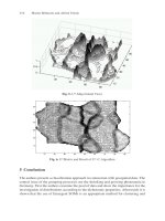
6. Experimental Mobile Platforms
In collaboration with Oak Ridge National Laboratories and Nomadic Technolo-
gies, we have completed the design and construction of two holonomic mobile
platforms (see Figure 3). Each platform is equipped with a PUMA 560 arm,
various sensors, a multi-processor computer system, a multi-axis controller, and
sufficient battery power to allow for autonomous operation. The base consists
of three "lateral" orthogonal universal-wheel assemblies which allow the base
to translate and rotate holonomically in relatively flat office-like environments
[9].
The control strategies discussed above have been implemented on these
two platforms. Erasing a whiteboard, cooperating in carrying a basket, and
sweeping a desk are examples of tasks demonstrated with the Stanford Mobile
Platforms [10]. The dynamic coordination strategy has allowed full use of the
relatively high bandwidth of the PUMA. Object motion and force control per-
formance with the Stanford mobile platforms are comparable with the results
obtained with fixed base PUMA manipulators.
147
Figure 3. The Stanford Mobile Platforms
7. Conclusion
We have presented extensions of various operational space methodologies for
fixed-base manipulators to mobile manipulation systems. A vehicle/arm plat-
form is treated as a macro/mini structure. This redundant system is controlled
using a dynamic coordination strategy, which allows the mini structure's high
bandwidth to be fully utilized.
Cooperative operations between multiple platforms rely on the integration
of the
augmented object,
which describes the system's closed-chain dynamics,
and the
virtual linkage,
which characterizes internal forces. These models are
the basis for the decentralized control structure presented in [8].
Vehicle/arm coordination and cooperative operations have been imple-
mented on the two mobile manipulator platforms developed at Stanford Uni-
versity.
Acknowledgments
The financial support of Boeing, General Motors, Hitachi Construction Ma-
chinery, and NSF (grants IRI-9320017 and CAD-9320419) is gratefully acknowl-
edged. Many thanks to Alain Bowling, Oliver Brock, Arancha Casal, Kyong-
Sok Chang, Robert Holmberg, Francois Pin, Diego Ruspini, David Williams,
James Slater, John Slater, Stef Sonck, and Kazuhito Yokoi for their valuable
contributions to the design and construction of the Stanford Mobile Platforms.
148
8. References
1 Ullman, M., Cannon, R., Experiments in Global Navigation and Control of
a Free-Flying Space Robot. Proc. Winter Annual Meeting, Vol. 15, 1989,
pp. 37-43.
2 Umetani, Y., and Yoshida, K., Experimental Study on Two-Dimensional
Free-Flying Robot Satellite Model. Proc. NASA Conf. Space Telerobotics,
1989.
3 Papadopoulos, E., Dubowsky, S., Coordinated Manipulator/Spacecraft Mo-
tion Control for Space Robotic Systems. Proc. IEEE Int. Conf. Robotics
and Automation, 1991, pp. 1696-1701.
4 Khatib, O., A Unified Approach to Motion and Force Control of Robot
Manipulators: The Operational Space Formulation. IEEE J. Robotics
and Automation, vol. 3, no. 1, 1987, pp. 43-53.
5 Khatib, O., Inertial Properties in Robotics Manipulation: An Object-Level
Framework, Int. J. Robotics Research, vol. 14, no. 1, February 1995. pp.
19-36.
6 Williams, D. and Khatib, O., The Virtual Linkage: A Model for Internal
Forces in Multi-Grasp Manipulation. Proc. IEEE Int. Conf. Robotics
and Automation, 1993, pp. 1025-1030.
7 Williams, D. and Khatib, O., Multi-Grasp Manipulation," IEEE Int. Conf.
Robotics and Automation Video Proceedings 1995.
8 Khatib, O. Yokoi, K., Chang,K, Ruspini, D., Holmberg, R. Casal, A.,
Baader., A. "Force Strategies for Cooperative Tasks in Multiple Mobile
Manipulation Systems," Robotics Research 7, The Seventh International
Symposium, G. Giralt and G. Hirzinger, eds., Springer 1996, pp. 333-342.
9 Pin, F. G. and S. M. Killough, "A New Family of Omnidirectional and Holo-
nomic Wheeled Platforms for Mobile Robots", IEEE Trans. on Robotics
and Automation, Vol. 10, No. 4, August 1994, pp. 480-489.
10 Khatib, O., K. Yokoi, K. Chang, D. Ruspini, R. Holmberg, A. Casal, and
A. Baader. "The Robotic Assistant," IEEE Int. Conf. Robotics and
Automation Video Proceedings, 1996.
Part Three
Applications
Forestry Robotics - Why, What and When
Aarne Halme, Mika Vainio
Robotics for the Mining Industry
Peter L Corke, Jonathan M. Roberts, Graeme ]. Winstanley
HelpMate®, the Trackless Robotic Courier: A Perspective on the
Development of a Commercial Autonomous Mobile Robot
John M. Evans, Bala Krishnamurthy
Intelligent Wheelchairs and Assistant Robots
]osep Amat
Robots in Surgery
Alicia Casals
- why, what and when
Aarne Halme
Automation Technology Laboratory
Helsinki University of Technology
Espoo, Finland
aarne.halme~_.hut.fi
Mika Vainio
Automation Technology Laboratory
Helsinki University of Technology
Espoo, Finland
mika.vainio~.hut.fi
Abstract: This paper overviews critically the state of the art of robotics in
forestry applications and gives examples of potential development in the field.
Benefits and restraints of forestry robotics are analysed and a scenario of future
development is presented.
1. Introduction
Forestry is one of the oldest industries. Wood has been taken out from forests for
houses, constructions, ship building and later for pulp and paper for several hundred
of years. The technology has been, however, undeveloped relaying on manual
technology and animal power until very recently. For example, in the Nordic
countries Finland and Sweden, where the development has been probably the fastest
in the world the intensive use of machines started only in the mid 80's. Since then,
on the other hand, the development has been very fast. For example, the share of'
manually harvested industrial wood in Finland has decreased from about 80 % to
about only 5 % during the last ten years as is shown in Fig. 1.
~. Foiling
oporalions on industrial and state-owned
Iond
100
90
80
70
GO
50
40
30
20
10
O
1985 198G 1987 1986 1968 1890 1991 1992 1993
Fig. 1: Mechanisation of felling in Finland (see lafi/forestfin/)
* See www.automation.hut.fi for detailed presentation of the laboratory
152
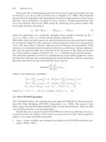
This means that the harvesting is done in practice by machines like those illustrated
in Fig.2.
Fig.2: Difficult environment (e.g. steep slopes and tight spaces) creates real problems for
machine and especially for robot applications
In other forestry intensive countries like Canada the trend is the same. The reason is
partly economical, but also social facts play an important role. Due to the moving of
people from the countryside to cities the amount of workers available for manual
harvesting is decreasing rapidly and thus mechanisation and automation are in fact
the only ways to replace this shortage.
The basis for the forestry robotics is the mentioned development. Although we are
in half-way in this development at the moment it can be said positively that within a
certain time frame we will see real robotic machines working in forests. In this
paper some existing prototype machines are presented and furthermore some
possible general guidelines for forestry robotics in future are given.
2. Development of forest machinery technology
The basic tasks in forestry are related in one hand to the flow of wood from forest to
factory and on the other hand to the maintenance operations like thinning and
silviculture by which the economic forest areas are taken care off. The basic tasks in
harvesting are felling, delimbing, cutting and transportation to the roadside.
Debarking which was done previously in forest is nowadays done in factories.
Felling, delimbing and cutting are done by harvesting machines (see Fig. 3), which
are operated by one person. One such machine has typically the capacity of 10-12
manual workers. The machines are partly automated and modern versions are
digitally controlled by CAN-bus based mechatronics. Typically the machine
measures automatically the volume of the wood processed by its processor head,
saves the results and communicates with the remote production control unit. The
control of machine operations is done by joy-sticks, but on a quite low level.
153
Operations like non-slipping motion control and coordinated control of the boom
have only recently been developed. However, many plans aiming to gradually
increase the level of automation exist, for example in boom operations. The
technology basis is now ready for robotic operations in a large extent.
Fig. 3: A harvester in operation
Second typical machine is the forwarder, shown in Fig. 4a, which transports the,.
wood from the felling side to the road side. it is a powerful tractor that takes a load
of several tons. Modern machines are also mechatronic like harvesters. For example,
an intelligent non-slipping motion controller is an important part of the control
system. There have also been developments to achieve an autonomous AGV-type
system for transportation, but this is still quite far in practice (Fig. 4b).
Fig. 4a: A normal forwarder Fig. 4b. An autonomous prototype vehicle,
which can be used e.g. for pulling trunks
out of forest (Modulaire Ltd.)
The boom for loading and unloading wood is also a target for roboticing. The
practical goal is to make these operations as short as possible and the operation of
the boom as easy as possible. Recently digitally controlled booms have been
developed for the markets. They can be controlled by the aid of joy-stick in
Cartesian coordinates which makes the control easier. However, the great challenge
is to automate the loading and unloading operations. Research on interactive
robotics, which makes high level boom control possible has been done already more
than ten years ago, see e.g. [ 1], but the results of practical product development are
still missing.
154
In forestry maintenance operations are still done mainly manually. Need for
automation is, however, as big as in harvesting. Planting is a task that has been tried
to automate for a long time without any major success. The problem is that the
ground quality varies in natural forest so much that finding proper places for plants
is difficult even for a man and thus very demanding for a machine. The other area,
where automation is needed is cleaning by which too tightly grown small trees are
removed to obtain more room for growth. This is done still today mainly manually
with motor saws because of the lack of proper machines.
3. Challenges for robotics
There are lots of challenges for robotics in forestry today. As stated before the
general trend is toward more automated machines. To move man out of machines is,
however, a big step and has not been taken this far except in some R&D projects (as
to the authors' knowledge). There are two reasons for this. The first is the
complicated environment. Forest is highly unstructured and uneven. Furthermore
the ground quality varies considerably. Autonomous motion and above all
autonomous working in such an environment need highly developed perception and
adaptation capabilities from the robot. The second reason is the economics.
Unmanned robotic vehicles also need maintenance and services by man. The
simplest way to solve this problem is to let the vehicles have operators. However, a
concept where a single operator can take care of several machines simultaneously is
of interest because it can increase efficiency considerably. This means that the
remote control technology will probably have the first priority in the process of
removing the man out of the machine. It is also an interesting solution for safety
problems that are encountered when working in mountain areas on steep slopes.
Before unmanned machines will be reality many steps must be taken to increase the
usability of today's machines by adding robotic features to them. This means that
some subtasks, like those of boom operations, machine locomotion (e.g., walking
machine, see later on), thinning operations, planting, etc. can be automated and
controlled by the operator. The use of only high level commands provides the
operator time to concentrate on more demanding perception, assessment and
planning tasks that are more difficult to automate. An example of such task division
is a high level control of the harvester processor boom. At the moment the operator
controls all motions of the boom. We could well think of a system in which the
operator only chooses the next tree to be harvested by pointing it with a laser
pointer. After that the rest of the task, i.e., controlling the boom to the tree, felling,
delimbing and cutting, is done automatically. The laser pointer defines the location
of the tree accurately enough in the machine based coordinate system. Nowadays it
is relatively easy to make a robot control system that executes the mentioned
subtasks, see e.g. [2].
Some of the tasks in forestry are of such nature that unmanned fully robotic type of
technology is sound solution also from an economical point of view. In some
countries forestry reminds of traditional farming. Extremely rapidly growing trees
(e.g. eucalyptus trees in Portugal) are planted in regular lines with very little space