Multi carrier and spread spectrum systems phần 3 ppsx
Bạn đang xem bản rút gọn của tài liệu. Xem và tải ngay bản đầy đủ của tài liệu tại đây (206.34 KB, 30 trang )
42 Fundamentals
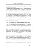
SF = 1
SF = 2 SF = 4 SF = 8
(1)
(1, 1)
(1, −1)
(1, 1, 1, 1)
(1, 1, −1, −1)
(1, −1, 1, −1)
(1, −1, −1, 1)
(1, 1, 1, 1, 1, 1, 1, 1)
(1, 1, 1, 1, −1, −1, −1, −1)
(1, 1, −1, −1, 1, 1, −1, −1)
(1, 1, −1, −1, −1, −1, 1, 1)
(1, −1, 1, −1, 1, −1, 1, −1)
(1, −1, 1, −1, −1, 1, −1, 1)
(1, −1, −1, 1, 1, −1, −1, 1)
(1, −1, −1, 1, −1, 1, 1, −1)
(C)
(C, C)
(C, −C)
Rule:
Figure 1-17 Variable length orthogonal spreading code generation
share the same bandwidth at the same time and separate the data by applying different
user specific spreading codes, i.e., the separation of the users signals is carried out in
the code domain. Moreover, both schemes apply multi-carrier modulation to reduce the
symbol rate and, thus, the amount of ISI per sub-channel. This ISI reduction is significant
in spread spectrum systems where high chip rates occur.
The difference between MC-CDMA and MC-DS-CMDA is the allocation of the chips
to the sub-channels and OFDM symbols. This difference is illustrated in Figures 1-18
and 1-19. The principle of MC-CDMA is to map the chips of a spread data symbol in
frequency direction over several parallel sub-channels while MC-DS-CDMA maps the
chips of a spread data symbol in the time direction over several multi-carrier symbols.
MC-CDMA transmits a data symbol of a user simultaneously on several narrowband
sub-channels. These sub-channels are multiplied by the chips of the user-specific spread-
ing code, as illustrated in Figure 1-18. Multi-carrier modulation is realized by using the
low-complex OFDM operation. Since the fading on the narrowband sub-channels can
0
1
•
L-1
0
1
•
L-1
data symbols
T
b
spread data symbols
spreading code
sub-carrier
f
0
sub-carrier
f
1
sub-carrier
f
N
c
−1
•
{
T
s
Figure 1-18 MC-CDMA signal generation for one user
Multi-Carrier Spread Spectrum 43
data symbols
spread data symbols
spreading code
serial-
to-
parallel
converter
01
•
L − 1
sub-carrier
f
0
sub-carrier
f
1
sub-carrier
f
N
c
−1
01
•
L − 1
•
{
T
s
Figure 1-19 MC-DS-CDMA signal generation for one user
be considered flat, simple equalization with one complex-valued multiplication per sub-
channel can be realized. MC-CDMA offers a flexible system design, since the spreading
code length does not have to be chosen equal to the number of sub-carriers, allowing
adjustable receiver complexities. This flexibility is described in detail in Chapter 2.
MC-DS-CDMA serial-to-parallel converts the high-rate data symbols into parallel low-
rate sub-streams before spreading the data symbols on each sub-channel with a user-
specific spreading code in time direction, which corresponds to direct sequence spreading
on each sub-channel. The same spreading codes can be applied on the different sub-
channels. The principle of MC-DS-CDMA is illustrated in Figure 1-19.
MC-DS-CDMA systems have been proposed with different multi-carrier modulation
schemes, also without OFDM, such that within the description of MC-DS-CDMA the
general term multi-carrier symbol instead of OFDM symbol is used. The MC-DS-CDMA
schemes can be subdivided in schemes with broadband sub-channels and schemes with
narrowband sub-channels. Systems with broadband sub-channels typically apply only
few numbers of sub-channels, where each sub-channel can be considered as a classical
DS-CDMA system with reduced data rate and ISI, depending on the number of parallel
DS-CDMA systems. MC-DS-CDMA systems with narrowband sub-channels typically use
high numbers of sub-carriers and can be efficiently realized by using the OFDM operation.
Since each sub-channel is narrowband and spreading is performed in time direction, these
schemes can only achieve a time diversity gain if no additional measures such as coding
or interleaving are applied.
Both multi-carrier spread spectrum concepts are described in detail in Chapter 2.
1.4.2 Advantages and Drawbacks
In Table 1-7, the main advantages and drawbacks of MC-CDMA and MC-DS-CDMA
are summarized.
A first conclusion from this table can be derived:
— The high spectral efficiency and the low receiver complexity of MC-CDMA makes it
a good candidate for the downlink of a cellular system.
— The low PAPR property of MC-DS-CDMA makes it more appropriate for the uplink
of a multiuser system.
44 Fundamentals
Table 1-7 Advantages and drawbacks of MC-CDMA and MC-DS-CDMA
MC-CDMA MC-DS-CDMA
Advantages Disadvantages Advantages Disadvantages
–Simple
implementation with
HT and FFT
–Lowcomplex
receivers
– High spectral
efficiency
– High frequency
diversity gain due to
spreading in
frequency direction
–HighPAPR
especially
in the
uplink
– Synchronous
transmission
– Low PAPR in the
uplink
– High time
diversity gain due
to spreading in
time direction
– ISI and/or ICI can
occur, resulting in
more complex
receivers
– Less spectral efficient
if other multi-carrier
modulation schemes
than OFDM are used
1.4.3 Examples of Future Application Areas
Multi-carrier spread spectrum concepts have been developed for a wide variety of appli-
cations.
Cellular mobile radio: Due to the high spectral efficiency of MC-CDMA, it is a promis-
ing candidate for the high rate downlink with peak data rates in the order of 100 Mbit/s
for the fourth generation of mobile radio systems [2]. In the uplink, where data rates in
the order of several 20 Mbit/s are considered, MC-DS-CDMA seems to be a promising
candidate since it has a lower PAPR compared to MC-CDMA, thus increasing the power
efficiency of the mobile terminal. In [20] a further concept of MC-CDMA system for
mobile cellular system has been proposed.
DVB-T return link: The DVB-T interactive point to multi-point (PMP) network is
intended to offer a variety of services requiring different data rates [15]. Therefore, the
multiple access scheme needs to be flexible in terms of data rate assignment to each
subscriber. As in the downlink terrestrial channel, its return channels suffer especially
from high multipath propagation delays. A derivative of MC-CDMA, namely OFDMA,
is already adopted in the standard. Several orthogonal sub-carriers are assigned to each
terminal station. However, the assignment of these sub-carriers during the time is hopped
following a given spreading code.
MMDS/LMDS (FWA): The aim of microwave/local multi-point distribution systems
(MMDS/LMDS) or fixed broadband wireless access (FWA) systems is to provide wire-
less high speed services with, e.g., IP/ATM to fixed positioned terminal stations with a
coverage area from 2 km up to 20 km. In order to maintain reasonably low RF costs
and good penetration of the radio signals for residential applications, the FWA systems
typically use below 10 GHz carrier frequencies, e.g., the MMDS band (2.5–2.7 GHz) or
around 5 GHz. As in the DVB-T return channel, OFDMA with frequency hopping for
FWA below 10 GHz is proposed [17][27]. However, for microwave frequencies above 10
GHz, e.g., LMDS, the main channel impairment will be the high amount of CCI due to
the dense frequency reuse in a cellular environment. In [32] a system architecture based
References 45
on MC-CDMA for FWA/LMDS applications is proposed. The suggested system provides
a high capacity, is quite robust against multipath effects, and can offer service coverage
not only to subscribers with LOS but also to subscribers who do not have LOS.
Aeronautical communications: An increase in air traffic will lead to bottlenecks in
air traffic handling en route and on ground. Airports have been identified as one of
the most capacity-restricted factors in the future if no counter-measures are taken. New
digital standards should replace current analog air traffic control systems. Different con-
cepts for future air traffic control based on multi-carrier spread spectrum have been
proposed [23][24].
More potential application fields for multi-carrier spread spectrum are in wireless indoor
communications [50] and broadband underwater acoustic communications [35].
1.5 References
[1] Adachi F., Sawahashi M. and Suda H., “Wideband CDMA for next generation mobile communications
systems,” IEEE Communications Magazine, vol. 26, pp. 56–69, June 1988.
[2] Atarashi H., Maeda N., Abeta S. and Sawahashi M., “Broadband packet wireless access based on VSF-
OFCDM and MC/DS-CDMA,” in Proc. IEEE International Symposium on Personal, Indoor and Mobile
Radio Communications (PIMRC 2002), Lisbon, Portugal, pp. 992–997, Sept. 2002.
[3] Baier A., Fiebig U C., Granzow W., Koch W., Teder P. and Thielecke J., “Design study for a CDMA-
based third-generation mobile radio system, “IEEE Journal on Selected Areas in Communications, vol. 12,
pp. 733–734, May 1994.
[4] Berruto E., Gudmundson M., Menolascino R., Mohr W. and Pizarroso M., “Research activities on UMTS
radio interface, network architectures, and planning,” IEEE Communications Magazine, vol. 36, pp. 82–95,
Feb. 1998.
[5] Bingham J.A.C., “Multicarrier modulation for data transmission: An idea whose time has come,” IEEE
Communications Magazine, vol. 28, pp. 5–14, May 1990.
[6] Chouly A., Brajal A. and Jourdan S., “Orthogonal multicarrier techniques applied to direct sequence spread
spectrum CDMA systems,” in Proc. IEEE Global Telecommunications Conference (GLOBECOM’93),
Houston, USA, pp. 1723–1728, Nov./Dec. 1993.
[7] CODIT, “Final propagation model,” Report R2020/TDE/PS/DS/P/040/b1, 1994.
[8] COST 207, “Digital land mobile radio communications,” Final Report, 1989.
[9] COST 231, “Digital mobile radio towards future generation systems,” Final Report, 1996.
[10] COST 259, “Wireless flexible personalized communications,” Final Report, L.M. Correira (ed.), John
Wiley & Sons, 2001.
[11] DaSilva V. and Sousa E.S., “Performance of orthogonal CDMA codes for quasi-synchronous commu-
nication systems,” in Proc. IEEE International Conference on Universal Personal Communications
(ICUPC’93), Ottawa, Canada, pp. 995–999, Oct. 1993.
[12] Dinan E.H. and Jabbari B. “Spreading codes for direct sequence CDMA and wideband CDMA cellular
networks,” IEEE Communications Magazine, vol. 26, pp. 48–54, June 1988.
[13] Dixon R.C., Spread Spectrum Systems. New York: John Wiley & Sons, 1976.
[14] Engels M. (ed.), Wireless OFDM Systems: How to Make Them Work. Boston: Kluwer Academic Publishers,
2002.
[15] ETSI DVB-RCT (EN 301 958), “Interaction channel for digital terrestrial television (RCT) incorporating
multiple access OFDM,” Sophia Antipolis, France, March 2001.
[16] ETSI DVB-T (EN 300 744), “Digital video broadcasting (DVB); framing structure, channel coding and
modulation for digital terrestrial television,” Sophia Antipolis, France, July 1999.
[17] ETSI HIPERMAN (Draft TS 102 177), “High performance metropolitan local area networks, Part 1:
Physical layer,” Sophia Antipolis, France, Feb. 2003.
[18] ETSI UMTS (TR 101 112), “Universal mobile telecommunications system (UMTS),” Sophia Antipolis,
France, 1998.
46 Fundamentals
[19] Fazel K., “Performance of CDMA/OFDM for mobile communication system,” in Proc. IEEE International
Conference on Universal Personal Communications (ICUPC’93), Ottawa, Canada, pp. 975–979, Oct.
1993.
[20] Fazel K., Kaiser S. and Schnell M., “A flexible and high performance cellular mobile communications sys-
tem based on multi-carrier SSMA,” Wireless Personal Communications, vol. 2, nos. 1 & 2, pp. 121–144,
1995.
[21] Fazel K. and Papke L., “On the performance of convolutionally-coded CDMA/OFDM for mobile com-
munication system,” in Proc. IEEE International Symposium on Personal, Indoor and Mobile Radio
Communications (PIMRC’93), Yokohama, Japan, pp. 468–472, Sept. 1993.
[22] Fettweis G., Bahai A.S. and Anvari K., “On multi-carrier code division multiple access (MC-CDMA)
modem design,” in Proc. IEEE Vehicular Technology Conference (VTC’94), Stockholm, Sweden,
pp. 1670–1674, June 1994.
[23] Haas E., Lang H. and Schnell M., “Development and implementation of an advanced airport data link
based on multi-carrier communications,” European Transactions on Telecommunications (ETT), vol. 13,
no. 5, pp. 447–454, Sept./Oct. 2002.
[24] Haindl B., “Multi-carrier CDMA for air traffic control air/ground communication,” in Proc. Interna-
tional Workshop on Multi-Carrier Spread-Spectrum & Related Topics (MC-SS 2001), Oberpfaffenhofen,
Germany, pp. 77–84, Sept. 2001.
[25] Hara H. and Prasad R., “Overview of multicarrier CDMA,” IEEE Communications Magazine, vol. 35,
pp. 126–133, Dec. 1997.
[26] Heiskala J. and Terry J., OFDM Wireless LANs: A Theoretical and Practical Guide. Indianapolis: SAMS,
2002.
[27] IEEE 802.16ab-01/01, “Air interface for fixed broadband wireless access systems – Part A: Systems
between 2 and 11 GHz,” IEEE 802.16, June 2000.
[28] Joint Technical Committee (JTC) on Wireless Access, Final Report on RF Channel Characterization,
JTC(AIR)/93.09.23-238R2, Sep. 1993.
[29] Kaiser S., Multi-Carrier CDMA Mobile Radio Systems – Analysis and Optimization of Detection, Decod-
ing, and Channel Estimation.D
¨
usseldorf: VDI-Verlag, Fortschritt-Berichte VDI, series 10, no. 531, 1998,
PhD thesis.
[30] Ketchum J.W. and Proakis J.G., “Adaptive algorithms for estimating and suppressing narrow band inter-
ference in PN spread spectrum systems,” IEEE, Transactions on Communications, vol. 30, pp. 913–924,
May 1982.
[31] Kondo S. and Milstein L.B., “On the use of multicarrier direct sequence spread spectrum systems,” in
Proc. IEEE Military Communications Conference (MILCOM’93), Boston, USA, pp. 52–56, Oct. 1993.
[32] Li J. and Kaverhard M., “Multicarrier orthogonal-CDMA for fixed wireless access applications,” Interna-
tional Journal of Wireless Information Network, vol. 8, no. 4, pp. 189–201, Oct. 2001.
[33] Medbo J. and Schramm P., “Channel models for HIPERLAN/2 in different indoor scenarios,” Technical
Report ETSI EP BRAN, 3ERI085B, March 1998.
[34] Milstein L.B., “Interference rejection techniques in spread spectrum communications,” Proceedings of the
IEEE, vol. 76, pp. 657–671, June 1988.
[35] Ormondroyd R.F., Lam W.K. and Davies J., “A multi-carrier spread spectrum approach to broadband
underwater acoustic communications,” in Proc. International Workshop on Multi-Carrier Spread Spectrum
& Related Topics (MC-SS’99), Oberpfaffenhofen, Germany, pp. 63–70, Sept. 1999.
[36] Parsons D., The Mobile Radio Propagation Channel. New York: John Wiley & Sons, 1992.
[37] Petroff A. and Withington P., “Time modulated ultra-wideband (TM-UWB) overview,” in Proc. Wireless
Symposium 2000, San Jose, USA, Feb. 2000.
[38] Pickholtz R.L., Milstein L.B. and Schilling D.L., “Spread spectrum for mobile communications”, IEEE
Transactions on Vehicular Technology, vol. 40, no. 2, pp. 313–322, May 1991.
[39] Pickholtz R.L., Schilling D.L. and Milstein L.B., “Theory of spread spectrum communications – a tuto-
rial,” IEEE Transactions on Communications, vol. 30, pp. 855–884, May 1982.
[40] Proakis J.G., Digital Communications. New York: McGraw-Hill, 1995.
[41] Sarwate D.V. and Pursley M.B., “Crosscorrelation properties of pseudo-random and related sequences,”
Proceedings of the IEEE, vol. 88, pp. 593–619, May 1998.
[42] TIA/EIA/IS-95, “Mobile station-base station compatibility standard for dual mode wideband spread spec-
trum cellular system,” July 1993.
References 47
[43] Turin G.L., “Introduction to spread spectrum anti-multipath techniques and their application to urban
digital radio,” Proceedings of the IEEE, vol. 68, pp. 328–353, March 1980.
[44] UTRA, Submission of Proposed Radio Transmission Technologies, SMG2, 1998.
[45] Vandendorpe L., “Multitone direct sequence CDMA system in an indoor wireless environment,” in
Proc. IEEE First Symposium of Communications and Vehicular Technology, Delft, The Netherlands,
pp. 4.1.1–4.1.8, Oct. 1993.
[46] van Nee R. and Prasad R., OFDM for Wireless Multimedia Communications. Boston: Artech House Pub-
lishers, 2000.
[47] Viterbi A.J., “Spread spectrum communications – myths and realities,” IEEE Communications Magazine,
pp. 11–18, May 1979.
[48] Viterbi A.J., CDMA: Principles of Spread Spectrum Communication. Reading: Addison-Wesley, 1995.
[49] Weinstein S.B. and Ebert P.M., “Data transmission by frequency-division multiplexing using the discrete
Fourier transform,” IEEE Transactions on Communication Technology, vol. 19, pp. 628–634, Oct. 1971.
[50] Yee N., Linnartz J.P., and Fettweis G., “Multi-carrier CDMA in indoor wireless radio networks,” in Proc.
IEEE International Symposium on Personal, Indoor and Mobile Radio Communications (PIMRC’93),
Yokohama, Japan, pp. 109–113, Sept. 1993.
2
MC-CDMA and MC-DS-CDMA
In this chapter, the different concepts of the combination of multi-carrier transmission
with spread spectrum, namely MC-CDMA and MC-DS-CDMA are analyzed. Several
single-user and multiuser detection strategies and their performance in terms of BER and
spectral efficiency in a mobile communications system are examined.
2.1 MC-CDMA
2.1.1 Signal Structure
The basic MC-CDMA signal is generated by a serial concatenation of classical DS-
CDMA and OFDM. Each chip of the direct sequence spread data symbol is mapped onto
a different sub-carrier. Thus, with MC-CDMA the chips of a spread data symbol are
transmitted in parallel on different sub-carriers, in contrast to a serial transmission with
DS-CDMA. The number of simultaneously active users
1
in an MC-CDMA mobile radio
system is K.
Figure 2-1 shows multi-carrier spectrum spreading of one complex-valued data symbol
d
(k)
assigned to user k. The rate of the serial data symbols is 1/T
d
. For brevity, but
without loss of generality, the MC-CDMA signal generation is described for a single data
symbol per user as far as possible, such that the data symbol index can be omitted. In
the transmitter, the complex-valued data symbol d
(k)
is multiplied with the user specific
spreading code
c
(k)
= (c
(k)
0
,c
(k)
1
, ,c
(k)
L−1
)
T
(2.1)
of length L = P
G
. The chip rate of the serial spreading code c
(k)
before serial-to-parallel
conversion is
1
T
c
=
L
T
d
(2.2)
1
Values and functions related to user k are marked by the index
(k)
,wherek may take on the values 0, ,
K −1.
Multi-Carrier and Spread Spectrum Systems K. Fazel and S. Kaiser
2003 John Wiley & Sons, Ltd ISBN: 0-470-84899-5
50 MC-CDMA and MC-DS-CDMA
d
(k)
s
(k)
x
(k)
spreader
c
(k)
serial-to-parallel
converter
OFDM
S
L− 1
(k)
S
0
(k)
Figure 2-1 Multi-carrier spread spectrum signal generation
and it is L times higher than the data symbol rate 1/T
d
. The complex-valued sequence
obtained after spreading is given in vector notations by
s
(k)
= d
(k)
c
(k)
= (S
(k)
0
,S
(k)
1
, ,S
(k)
L−1
)
T
.(2.3)
A multi-carrier spread spectrum signal is obtained after modulating the components
S
(k)
l
,l = 0, ,L−1, in parallel onto L sub-carriers. With multi-carrier spread spectrum,
each data symbol is spread over L sub-carriers. In cases where the number of sub-carriers
N
c
of one OFDM symbol is equal to the spreading code length L, the OFDM symbol
duration with multi-carrier spread spectrum including a guard interval results in
T
s
= T
g
+ LT
c
.(2.4)
In this case one data symbol per user is transmitted in one OFDM symbol.
2.1.2 Downlink Signal
In the synchronous downlink, it is computationally efficient to add the spread signals of
the K users before the OFDM operation as depicted in Figure 2-2. The superposition of
the K sequences s
(k)
results in the sequence
s =
K−1
k=0
s
(k)
= (S
0
,S
1
, ,S
L−1
)
T
.(2.5)
An equivalent representation for s in the downlink is
s = Cd,(2.6)
spreader
c
(0)
OFDM
d
(0)
s
S
0
S
L− 1
x
serial-to-parallel
converter
+
spreader
c
(K− 1)
d
(K− 1)
Figure 2-2 MC-CDMA downlink transmitter
MC-CDMA 51
where
d = (d
(0)
,d
(1)
, ,d
(K−1)
)
T
(2.7)
is the vector with the transmitted data symbols of the K active users and C is the spreading
matrix given by
C = (c
(0)
, c
(1)
, ,c
(K−1)
). (2.8)
The MC-CDMA downlink signal is obtained after processing the sequence s in the
OFDM block according to (1.26). By assuming that the guard time is long enough to
absorb all echoes, the received vector of the transmitted sequence s after inverse OFDM
and frequency deinterleaving is given by
r = Hs+ n = (R
0
,R
1
, ,R
L−1
)
T
,(2.9)
where H is the L × L channel matrix and n is the noise vector of length L. The vector r
is fed to the data detector in order to get a hard or soft estimate of the transmitted data.
For the description of the multiuser detection techniques, an equivalent notation for the
received vector r is introduced,
r = Ad+ n = (R
0
,R
1
, ,R
L−1
)
T
.(2.10)
The system matrix A for the downlink is defined as
A = HC.(2.11)
2.1.3 Uplink Signal
In the uplink, the MC-CDMA signal is obtained directly after processing the sequence
s
(k)
of user k in the OFDM block according to (1.26). After inverse OFDM and frequency
deinterleaving, the received vector of the transmitted sequences s
(k)
is given by
r =
K−1
k=0
H
(k)
s
(k)
+ n = (R
0
,R
1
, ,R
L−1
)
T
,(2.12)
where H
(k)
contains the coefficients of the sub-channels assigned to user k. The uplink
is assumed to be synchronous in order to achieve the high spectral efficiency of OFDM.
The vector r is fed to the data detector in order to get a hard or soft estimate of the
transmitted data. The system matrix
A = (a
(0)
, a
(1)
, ,a
(K−1)
)(2.13)
comprises K user-specific vectors
a
(k)
= H
(k)
c
(k)
= (H
(k)
0,0
c
(k)
0
,H
(k)
1,1
c
(k)
1
, ,H
(k)
L−1,L−1
c
(k)
L−1
)
T
.(2.14)
2.1.4 Spreading Techniques
The spreading techniques in MC-CDMA schemes differ in the selection of the spreading
code and the type of spreading. As well as a variety of spreading codes, different strategies
52 MC-CDMA and MC-DS-CDMA
exist to map the spreading codes in time and frequency direction with MC-CDMA. Finally,
the constellation points of the transmitted signal can be improved by modifying the phase
of the symbols to be distinguished by the spreading codes.
2.1.4.1 Spreading Codes
Various spreading codes exist which can be distinguished with respect to orthogonal-
ity, correlation properties, implementation complexity and peak-to-average power ratio
(PAPR). The selection of the spreading code depends on the scenario. In the synchronous
downlink, orthogonal spreading codes are of advantage, since they reduce the multiple
access interference compared to non-orthogonal sequences. However, in the uplink, the
orthogonality between the spreading codes gets lost due to different distortions of the
individual codes. Thus, simple PN sequences can be chosen for spreading in the uplink.
If the transmission is asynchronous, Gold codes have good cross-correlation properties.
In cases where pre-equalization is applied in the uplink, orthogonality can be achieved
at the receiver antenna, such that in the uplink orthogonal spreading codes can also be
of advantage.
Moreover, the selection of the spreading code has influence on the PAPR of the trans-
mitted signal (see Chapter 4). Especially in the uplink, the PAPR can be reduced by
selecting, e.g., Golay or Zadoff–Chu codes [8][35][36][39][52]. Spreading codes appli-
cable in MC-CDMA systems are summarized in the following.
Walsh-Hadamard codes: Orthogonal Walsh–Hadamard codes are simple to generate
recursively by using the following Hadamard matrix generation,
C
L
=
C
L/2
C
L/2
C
L/2
−C
L/2
, ∀L = 2
m
,m≥ 1, C
1
= 1. (2.15)
The maximum number of available orthogonal spreading codes is L which determines
the maximum number of active users K.
The Hadamard matrix generation described in (2.15) can also be used to perform an
L-ary Walsh–Hadamard modulation which in combination with PN spreading can be
applied in the uplink of an MC-CDMA systems [11][12].
Fourier codes: The columns of an FFT matrix can also be considered as spreading codes,
which are orthogonal to each other. The chips are defined as
c
(k)
l
= e
−j 2πlk/L
.(2.16)
Thus, if Fourier spreading is applied in MC-CDMA systems, the FFT for spreading and
the IFFT for the OFDM operation cancels out if the FFT and IFFT are the same size, i.e.,
the spreading is performed over all sub-carriers [7]. Thus, the resulting scheme is a single-
carrier system with cyclic extension and frequency domain equalizer. This scheme has a
dynamic range of single-carrier systems. The computational efficient implementation of
the more general case where the FFT spreading is performed over groups of sub-carriers
which are interleaved equidistantly is described in [8]. A comparison of the amplitude
distributions between Hadamard codes and Fourier codes shows that Fourier codes result
in an equal or lower peak-to-average power ratio [9].
MC-CDMA 53
Pseudo noise (PN) spreading codes: The property of a PN sequence is that the sequence
appears to be noise-like if the construction is not known at the receiver. They are typically
generated by using shift registers. Often used PN sequences are maximum-length shift
register sequences, known as m-sequences. A sequence has a length of
n = 2
m
− 1 (2.17)
bits and is generated by a shift register of length m with linear feedback [40]. The sequence
has a period length of n and each period contains 2
m−1
ones and 2
m−1
− 1 zeros, i.e., it
is a balanced sequence.
Gold codes: PN sequences with better cross-correlation properties than m-sequences are
the so-called Gold sequences [40]. A set of n Gold sequences is derived from a preferred
pair of m-sequences of length L = 2
n
− 1 by taking the modulo-2 sum of the first preferred
m-sequence with the n cyclically shifted versions of the second preferred m-sequence. By
including the two preferred m-sequences, a family of n + 2 Gold codes is obtained. Gold
codes have a three-valued cross correlation function with values {−1, −t(m),t(m)− 2}
where
t(m) =
2
(m+1)/2
+ 1form odd .
2
(m+2)/2
+ 1form even
(2.18)
Golay codes: Orthogonal Golay complementary codes can recursively be obtained by
C
L
=
C
L/2
C
L/2
C
L/2
−C
L/2
, ∀L = 2
m
,m 1, C
1
= 1,(2.19)
where the complementary matrix
C
L
is defined by reverting the original matrix C
L
.If
C
L
=
A
L
B
L
,(2.20)
and A
L
and B
L
are L × L/2 matrices, then
C
L
= [
A
L
−B
L
].(2.21)
Zadoff-Chu codes: The Zadoff–Chu codes have optimum correlation properties and are
a special case of generalized chirp-like sequences. They are defined as
c
(k)
l
=
e
j2πk(ql+l
2
/2)/L
for L even
e
j2πk(ql+l(l+1)/2)/L
for L odd
, (2.22)
where q is any integer, and k is an integer, prime with L.IfL is a prime number,
a set of Zadoff–Chu codes is composed of L − 1 sequences. Zadoff–Chu codes have
an optimum periodic autocorrelation function and a low constant magnitude periodic
cross-correlation function.
Low-rate convolutional codes: Low-rate convolutional codes can be applied in CDMA
systems as spreading codes with inherent coding gain [50]. These codes have been applied
as alternative to the use of a spreading code followed by a convolutional code. In MC-
CDMA systems, low-rate convolutional codes can achieve good performance results for
54 MC-CDMA and MC-DS-CDMA
moderate numbers of users in the uplink [30][32][46]. The application of low-rate con-
volutional codes is limited to very moderate numbers of users since, especially in the
downlink, signals are not orthogonal between the users, resulting in possibly severe mul-
tiple access interference. Therefore, they cannot reach the high spectral efficiency of
MC-CDMA systems with separate coding and spreading.
2.1.4.2 Peak-to-Average Power Ratio (PAPR)
The variation of the envelope of a multi-carrier signal can be defined by the peak-to-
average power ratio (PAPR) which is given by
PAPR =
max |x
v
|
2
1
N
c
N
c
−1
v=0
|x
v
|
2
.(2.23)
The values x
v
, v = 0, ,N
c
− 1, are the time samples of an OFDM symbol. An addi-
tional measure to determine the envelope variation is the crest factor (CF) which is
CF =
√
PAPR.(2.24)
By appropriately selecting the spreading code, it is possible to reduce the PAPR of the
multi-carrier signal [4][36][39]. This PAPR reduction can be of advantage in the uplink
where low power consumption is required in the terminal station.
Uplink PAPR
The uplink signal assigned to user k results in
x
v
= x
(k)
v
.(2.25)
The PAPR for different spreading codes can be upper-bounded for the uplink by [35]
PAPR
2max
L−1
l=0
c
(k)
l
e
j2πlt/T
s
2
L
,(2.26)
assuming that N
c
= L. Table 2-1 summarizes the PAPR bounds for MC-CDMA uplink
signals with different spreading codes.
The PAPR bound for Golay codes and Zadoff–Chu codes is independent of the spread-
ing code length. When N
c
is a multiple of L, the PAPR of the Walsh-Hadamard code is
upper-bounded by 2N
c
.
Downlink PAPR
The time samples of a downlink multi-carrier symbol assuming synchronous transmission
are given as
x
v
=
K−1
k=0
x
(k)
v
.(2.27)
MC-CDMA 55
Table 2-1 PAPR bounds of MC-CDMA uplink signals;
N
c
= L
Spreading code PAPR
Walsh–Hadamard 2L
Golay 4
Zadoff–Chu 2
Gold 2
t(m)−1 −
t(m)+2
L
The PAPR of an MC-CDMA downlink signal with K users and N
c
= L can be upper-
bounded by [35]
PAPR
2max
K−1
k=0
L−1
l=0
c
(k)
l
e
j2πlt/T
s
2
L
.(2.28)
2.1.4.3 One- and Two-Dimensional Spreading
Spreading in MC-CDMA systems can be carried out in frequency direction, time direc-
tion or two-dimensional in time and frequency direction. An MC-CDMA system with
spreading only in the time direction is equal to an MC-DS-CDMA system. Spreading in
two dimensions exploits time and frequency diversity and is an alternative to the conven-
tional approach with spreading in frequency or time direction only. A two-dimensional
spreading code is a spreading code of length L where the chips are distributed in the
time and frequency direction. Two-dimensional spreading can be performed by a two-
dimensional spreading code or by two cascaded one-dimensional spreading codes. An
efficient realization of two-dimensional spreading is to use a one-dimensional spreading
code followed by a two-dimensional interleaver as illustrated in Figure 2-3 [23]. With two
cascaded one-dimensional spreading codes, spreading is first carried out in one dimension
with the first spreading code of length L
1
. In the next step, the data-modulated chips of
the first spreading code are again spread with the second spreading code in the second
dimension. The length of the second spreading code is L
2
. The total spreading length
with two cascaded one-dimensional spreading codes results in
L = L
1
L
2
.(2.29)
If the two cascaded one-dimensional spreading codes are Walsh–Hadamard codes, the
resulting two-dimensional code is again a Walsh–Hadamard code with total length L.
For large L, two-dimensional spreading can outperform one-dimensional in an uncoded
MC-CDMA system [13][42].
Two-dimensional spreading for maximum diversity gain is efficiently realized by using
a sufficiently long spreading code with L
D
O
,whereD
O
is the maximum achievable
two-dimensional diversity (see Section 1.1.7). The spread sequence of length L has to be
appropriately interleaved in time and frequency, such that all chips of this sequence are
faded independently as far as possible.
56 MC-CDMA and MC-DS-CDMA
1D spreading 2D spreading
1st direction
2nd direction
interleaved
Figure 2-3 1D and 2D spreading schemes
Another approach with two-dimensional spreading is to locate the chips of the two-
dimensional spreading code as close together as possible in order to get all chips similarly
faded and, thus, preserve orthogonality of the spreading codes at the receiver as far as
possible [3][38]. Due to reduced multiple access interference, low complex receivers can
be applied. However, the diversity gain due to spreading is reduced such that powerful
channel coding is required. If the fading over all chips of a spreading code is flat, the
performance of conventional OFDM without spreading is the lower bound for this spread-
ing approach; i.e., the BER performance of an MC-CDMA system with two-dimensional
spreading and Rayleigh fading which is flat over the whole spreading sequence results
in the performance of OFDM with L = 1 shown in Figure 1-3. One- or two-dimensional
spreading concepts with interleaving of the chips in time and/or frequency are lower-
bounded by the diversity performance curves in Figure 1-3 which are assigned to the
chosen spreading code length L.
2.1.4.4 Rotated Constellations
With spreading codes like Walsh–Hadamard codes, the achievable diversity gain degrades,
if the signal constellation points of the resulting spread sequence s in the downlink con-
centrate their energy in less than L sub-channels, which in the worst case is only in one
sub-channel while the signal on all other sub-channels is zero. Here we consider a full
loaded scenario with K = L. The idea of rotated constellations [8] is to guarantee the
existence of M
L
distinct points at each sub-carrier for a transmitted alphabet size of M
and a spreading code length of L and that all points are nonzero. Thus, if all except one
sub-channel are faded out, detection of all data symbols is still possible.
With rotated constellations, the L data symbols are rotated before spreading such that
the data symbol constellations are different for each of the L data symbols of the transmit
symbol vector s. This can be achieved by rotating the phase of the transmit symbol
alphabet of each of the L spread data symbols by a fraction proportional to 1/L.The
rotation factor for user k is
r
(k)
= e
j2πk/(M
rot
L)
,(2.30)
where M
rot
is a constant whose choice depends on the symbol alphabet. For example,
M
rot
= 2 for BPSK and M
rot
= 4 for QPSK. For M-PSK modulation, the constant
MC-CDMA 57
(a) (b)
I
Q
Q
I
Figure 2-4 Constellation points after Hadamard spreading a) nonrotated, b) rotated, both for
BPSK and L = 4
M
rot
= M. The constellation points of the Walsh-Hadamard spread sequence s with BPSK
modulation with and without rotation is illustrated in Figure 2-4 for a spreading code
length of L = 4.
Spreading with rotated constellations can achieve better performance than the use of
nonrotated spreading sequences. The performance improvements strongly depend on the
chosen symbol mapping scheme. Large symbol alphabets reduce the degree of freedom
for placing the points in a rotated signal constellation and decrease the gains. Moreover,
the performance improvements with rotated constellations strongly depend on the chosen
detection techniques. For higher-order symbol mapping schemes, relevant performance
improvements require the application of powerful multiuser detection techniques. The
achievable performance improvements in SNR with rotated constellations can be in the
order of several dB at a BER of 10
−3
for an uncoded MC-CDMA system with QPSK in
fading channels.
2.1.5 Detection Techniques
Data detection techniques can be classified as either single-user detection (SD) or mul-
tiuser detection (MD). The approach using SD detects the user signal of interest by not
taking into account any information about multiple access interference. In MC-CDMA
mobile radio systems, SD is realized by one tap equalization to compensate for the distor-
tion due to flat fading on each sub-channel, followed by user-specific despreading. As in
OFDM, the one tap equalizer is simply one complex-valued multiplication per sub-carrier.
If the spreading code structure of the interfering signals is known, the multiple access
interference could not be considered in advance as noise-like, yielding SD to be subopti-
mal. The suboptimality of SD can be overcome with MD where the apriori knowledge
about the spreading codes of the interfering users is exploited in the detection process.
The performance improvements with MD compared to SD are achieved at the expense
of higher receiver complexity. The methods of MD can be divided into interference
cancellation (IC) and joint detection. The principle of IC is to detect the information of
the interfering users with SD and to reconstruct the interfering contribution in the received
signal before subtracting the interfering contribution from the received signal and detecting
the information of the desired user. The optimal detector applies joint detection with
maximum likelihood detection. Since the complexity of maximum likelihood detection
grows exponentially with the number of users, its use is limited in practice to applications
58 MC-CDMA and MC-DS-CDMA
y
. . .
r
parallel-to-serial
converter
d
^
(k)
inverse OFDM
single-user
or
multi-user
detector
d
^
R
0
R
L− 1
Figure 2-5 MC-CDMA receiver in the terminal station
with a small number of users. Simpler joint detection techniques can be realized by using
block linear equalizers.
An MC-CDMA receiver in the terminal station of user k is depicted in Figure 2-5.
2.1.5.1 Single-User Detection
The principle of single-user detection is to detect the user signal of interest by not tak-
ing into account any information about the multiple access interference. A receiver with
single-user detection of the data symbols of user k is shown in Figure 2-6.
After inverse OFDM the received sequence r is equalized by employing a bank of
adaptive one-tap equalizers to combat the phase and amplitude distortions caused by the
mobile radio channel on the sub-channels. The one tap equalizer is simply realized by
one complex-valued multiplication per sub-carrier. The received sequence at the output
of the equalizer has the form
u = Gr= (U
0
,U
1
, ,U
L−1
)
T
.(2.31)
The diagonal equalizer matrix
G =
G
0,0
0 ··· 0
0 G
1,1
0
.
.
.
.
.
.
.
.
.
00··· G
L−1,L−1
(2.32)
of dimension L × L represents the L complex-valued equalizer coefficients of the sub-
carriers assigned to s. The complex-valued output u of the equalizer is despread by
correlating it with the conjugate complex user-specific spreading code c
(k)∗
. The complex-
valued soft decided value at the output of the despreader is
v
(k)
= c
(k)∗
u
T
.(2.33)
r
d
^
(k)
equalizer
G
despreader
c
(k)*
quantizer
u
n
(k)
Figure 2-6 MC-CDMA single-user detection
MC-CDMA 59
The hard decided value of a detected data symbol is given by
ˆ
d
(k)
= Q{v
(k)
},(2.34)
where Q{·} is the quantization operation according to the chosen data symbol alphabet.
The term equalizer is generalized in the following, since the processing of the received
vector r according to typical diversity combining techniques is also investigated using the
SD scheme shown in Figure 2-6.
Maximum Ratio Combining (MRC): MRC weights each sub-channel with its respective
conjugate complex channel coefficient, leading to
G
l,l
= H
∗
l,l
,(2.35)
where H
l,l
,l = 0, ,L−1, are the diagonal components of H. The drawback of MRC
in MC-CDMA systems in the downlink is that it destroys the orthogonality between the
spreading codes and, thus, additionally enhances the multiple access interference. In the
uplink, MRC is the most promising single-user detection technique since the spreading
codes do not superpose in an orthogonal fashion at the receiver and maximization of the
signal-to-interference ratio is optimized.
Equal Gain Combining (EGC): EGC compensates only for the phase rotation caused by
the channel by choosing the equalization coefficients as
G
l,l
=
H
∗
l,l
|H
l,l
|
.(2.36)
EGC is the simplest single-user detection technique, since it only needs information about
the phase of the channel.
Zero Forcing (ZF): ZF applies channel inversion and can eliminate multiple access
interference by restoring the orthogonality between the spread data in the downlink with
an equalization coefficient chosen as
G
l,l
=
H
∗
l,l
|H
l,l
|
2
.(2.37)
The drawback of ZF is that for small amplitudes of H
l,l
the equalizer enhances noise.
Minimum Mean Square Error (MMSE) Equalization: Equalization according to the
MMSE criterion minimizes the mean square value of the error
ε
l
= S
l
− G
l,l
R
l
(2.38)
between the transmitted signal and the output of the equalizer. The mean square error
J
l
= E{|ε
l
|
2
} (2.39)
can be minimized by applying the orthogonality principle, stating that the mean square
error J
l
is minimum if the equalizer coefficient G
l,l
is chosen such that the error ε
l
is
orthogonal to the received signal R
∗
l
, i.e.,
E{ε
l
R
∗
l
}=0.(2.40)
60 MC-CDMA and MC-DS-CDMA
The equalization coefficient based on the MMSE criterion for MC-CDMA systems re-
sults in
G
l,l
=
H
∗
l,l
|H
l,l
|
2
+ σ
2
.(2.41)
The computation of the MMSE equalization coefficients requires knowledge about the
actual variance of the noise σ
2
. For very high SNRs, the MMSE equalizer becomes iden-
tical to the ZF equalizer. To overcome the additional complexity for the estimation of σ
2
,
a low-complex suboptimum MMSE equalization can be realized [21].
With suboptimum MMSE equalization, the equalization coefficients are designed such
that they perform optimally only in the most critical cases for which successful transmis-
sion should be guaranteed. The variance σ
2
is set equal to a threshold λ at which the
optimal MMSE equalization guarantees the maximum acceptable BER. The equalization
coefficient with suboptimal MMSE equalization results in
G
l,l
=
H
∗
l,l
|H
l,l
|
2
+ λ
(2.42)
and requires only information about H
l,l
. The value λ has to be determined during the
system design.
A controlled equalization can be applied in the receiver, which performs slightly worse
than suboptimum MMSE equalization [23]. Controlled equalization applies zero forcing
on sub-carriers where the amplitude of the channel coefficients exceeds a predefined
threshold a
th
. All other sub-carriers apply equal gain combining in order to avoid noise
amplification.
In the uplink G and H are user-specific.
2.1.5.2 Multiuser Detection
Maximum Likelihood Detection
The optimum multiuser detection technique exploits the maximum a posteriori (MAP)
criterion or the maximum likelihood criterion, respectively. In this section, two optimum
maximum likelihood detection algorithms are shown, namely the maximum likelihood
sequence estimation (MLSE), which optimally estimates the transmitted data sequence
d = (d
(0)
,d
(1)
, ,d
(K−1)
)
T
and the maximum likelihood symbol-by-symbol estimation
(MLSSE), which optimally estimates the transmitted data symbol d
(k)
. It is straightforward
that both algorithms can be extended to a MAP sequence estimator and to a MAP symbol-
by-symbol estimator by taking into account the apriori probability of the transmitted
sequence and symbol, respectively. When all possible transmitted sequences and symbols,
respectively, are equally probable apriori, the estimator based on the MAP criterion and
the one based on the maximum likelihood criterion are identical. The possible transmitted
data symbol vectors are d
µ
, µ = 0, ,M
K
− 1, where M
K
is the number of possible
transmitted data symbol vectors and M is the number of possible realizations of d
(k)
.
Maximum Likelihood Sequence Estimation (MLSE): MLSE minimizes the sequence
error probability, i.e., the data symbol vector error probability, which is equivalent to
MC-CDMA 61
maximizing the conditional probability P{d
µ
|r} that d
µ
was transmitted given the received
vector r. The estimate of d obtained with MLSE is
ˆ
d = arg max
d
µ
P {d
µ
|r},(2.43)
with arg denoting the argument of the function. If the noise N
l
is additive white Gaussian,
(2.43) is equivalent to finding the data symbol vector d
µ
that minimizes the squared
Euclidean distance
2
(d
µ
, r) =||r − Ad
µ
||
2
(2.44)
between the received and all possible transmitted sequences. The most likely transmitted
data vector is
ˆ
d = arg min
d
µ
2
(d
µ
, r). (2.45)
MLSE requires the evaluation of M
K
squared Euclidean distances for the estimation of
the data symbol vector
ˆ
d.
Maximum Likelihood Symbol-by-Symbol Estimation (MLSSE): MLSSE minimizes the
symbol error probability, which is equivalent to maximizing the conditional probability
P {d
(k)
µ
|r} that d
(k)
µ
was transmitted given the received sequence r. The estimate of d
(k)
obtained by MLSSE is
ˆ
d
(k)
= arg max
d
(k)
µ
P {d
(k)
µ
|r}.(2.46)
If the noise N
l
is additive white Gaussian the most likely transmitted data symbol
is
ˆ
d
(k)
= arg max
d
(k)
µ
∀d
µ
with same
realization of d
(k)
µ
exp
−
1
σ
2
2
(d
µ
, r)
.(2.47)
The increased complexity with MLSSE compared to MLSE can be observed in the
comparison of (2.47) with (2.45). An advantage of MLSSE compared to MLSE is that
MLSSE inherently generates reliability information for detected data symbols which can
be exploited in a subsequent soft decision channel decoder.
Block Linear Equalizer
The block linear equalizer is a suboptimum, low-complex multiuser detector which requires
knowledge about the system matrix A in the receiver. Two criteria can be applied to use
this knowledge in the receiver for data detection.
Zero Forcing Block Linear Equalizer: Joint detection applying a zero forcing block
linear equalizer delivers at the output of the detector the soft decided data vector
v = (A
H
A)
−1
A
H
r = (v
(0)
,v
(1)
, ,v
(K−1)
)
T
,(2.48)
where (·)
H
is the Hermitian transposition.
MMSE Block Linear Equalizer: An MMSE block linear equalizer delivers at the output
of the detector the soft decided data vector
v = (A
H
A + σ
2
I)
−1
A
H
r = (v
(0)
,v
(1)
, ,v
(K−1)
)
T
.(2.49)
62 MC-CDMA and MC-DS-CDMA
Hybrid combinations of block linear equalizers and interference cancellation schemes (see
the next section) are possible, resulting in block linear equalizers with decision feedback.
Interference Cancellation
The principle of interference cancellation is to detect and subtract interfering signals from
the received signal before detection of the wanted signal. It can be applied to reduce intra-
cell and inter-cell interference. Most detection schemes focus on intra-cell interference,
which will be further discussed in this section. Interference cancellation schemes can use
signals for reconstruction of the interference either obtained at the detector output (see
Figure 2-7), or at the decoder output (see Figure 2-8).
Both schemes can be applied in several iterations. Values and functions related to the
iteration j aremarkedbyanindex
[j]
,wherej maytakeonthevaluesj = 1, ,J
it
,and
J
it
is the total number of iterations. The initial detection stage is indicated by the index
[0]
.
Since the interference is detected more reliably at the output of the channel decoder than
at the output of the detector, the scheme with channel decoding included in the iterative
process outperforms the other scheme. Interference cancellation distinguishes between
parallel and successive cancellation techniques. Combinations of parallel and successive
interference cancellation are also possible.
Parallel Interference Cancellation (PIC): The principle of PIC is to detect and subtract
all interfering signals in parallel before detection of the wanted signal. PIC is suitable for
equalizer
despreader
k
channel
decoder
Π
−1
equalizer
despreader
g ≠ k
distortion
spreader
g ≠ k
symbol
demapper
symbol
mapper
symbol
demapper
hard interference evaluation without channel decoding
Figure 2-7 Hard interference cancellation scheme
equalizer
despreader
k
channel
decoder
Π
−1
equalizer
despreader
g ≠ k
distortion
spreader
g ≠ k
symbol
demapper
soft symbol
mapper
symbol
demapper
soft interference evaluation exploiting channel decoding
soft out
chan. dec.
Π
−1
Π tanh(.)
Figure 2-8 Soft interference cancellation scheme
MC-CDMA 63
systems where the interfering signals have similar power. In the initial detection stage,
the data symbols of all K active users are detected in parallel by single-user detection.
That is,
ˆ
d
(k)[0]
= Q{c
(k)∗
G
(k)[0]
r
T
},k= 0, ,K −1,(2.50)
where G
(k)[0]
denotes the equalization coefficients assigned to the initial stage. The fol-
lowing detection stages work iteratively by using the decisions of the previous stage to
reconstruct the interfering contribution in the received signal. The obtained interference
is subtracted, i.e., cancelled from the received signal, and the data detection is performed
again with reduced multiple access interference. Thus, the second and further detection
stages apply
ˆ
d
(k)[j]
= Q
c
(k)∗
G
(k)[j]
r −
K−1
g=0
g=k
H
(g)
d
(g)[j−1]
c
(g)
T
,j= 1, ,J
it
.(2.51)
where, except for the final stage, the detection has to be applied for all K users.
PIC can be applied with different detection strategies in the iterations. Starting with
EGC in each iteration [15] various combinations have been proposed [6][22][27]. Very
promising results are obtained with MMSE equalization adapted in the first iteration to
the actual system load and in all further iterations to MMSE equalization adapted to the
single-user case [21]. The application of MRC seems theoretically to be of advantage for
the second and further detection stages, since MRC is the optimum detection technique
in the multiple access interference free case, i.e., in the single-user case. However, if one
or more decision errors are made, MRC has a poor performance [22].
Successive Interference Cancellation (SIC): SIC detects and subtracts the interfering sig-
nals in the order of the interfering signal power. First, the strongest interferer is cancelled,
before the second strongest interferer is detected and subtracted, i.e.,
ˆ
d
(k)[j]
= Q{c
(k)∗
G
(k)[j]
(r − H
(g)
(d
(g)[j−1]
c
(g)
))
T
},(2.52)
where g is the strongest interferer in the iteration j, j = 1, ,J
it
. This procedure is
continued until a predefined stop criteria. SIC is suitable for systems with large power
variations between the interferers [6].
Soft-Interference Cancellation: Interference cancellation can use reliability information
about the detected interference in the iterative process. These schemes can be without [37]
and with [18][25] channel decoding in the iterative process, and are termed soft inter-
ference cancellation. If reliability information about the detected interference is taken
into account in the cancellation scheme, the performance of the iterative scheme can be
improved since error propagation can be reduced compared to schemes with hard decided
feedback. The block diagram of an MC-CDMA receiver with soft interference cancella-
tion is illustrated in Figure 2-8. The data of the desired user k are detected by applying
interference cancellation with reliability information. Before detection of user k’s data
in the lowest path of Figure 2-8 with an appropriate single-user detection technique, the
64 MC-CDMA and MC-DS-CDMA
contributions of the K − 1 interfering users g, g = 0, ,K − 1, and g = k is detected
with single-user detection and subtracted from the received signal. The principle of paral-
lel or successive interference cancellation or combinations of both can be applied within
a soft interference cancellation scheme.
In the following, we focus on the contribution of the interfering user g with g = k.The
soft decided values w
(g)[j]
are obtained after single-user detection, symbol demapping,
and deinterleaving. The corresponding log-likelihood ratios (LLRs) for channel decoding
are given by the vector l
(g)[j]
. LLRs are the optimum soft decided values which can be
exploited in a Viterbi decoder (see Section 2.1.7). From the subsequent soft-in/soft-out
channel decoder, besides the output of the decoded source bits, reliability information in
the form of LLRs of the coded bits can be obtained. These LLRs are given by the vector
l
(g)[j]
out
= (
(g)[j]
0,out
,
(g)[j]
1,out
, ,
(g)[j]
L
b
−1,out
)
T
.(2.53)
In contrast to the LLRs of the coded bits at the input of the soft-in/soft-out channel
decoder, the LLRs of the coded bits at the output of the soft-in/soft-out channel decoder
(g)[j]
κ,out
= ln
P {b
(g)
κ
=+1|w
(g)[j]
}
P {b
(g)
κ
=−1|w
(g)[j]
}
,κ= 0, ,L
b
− 1,(2.54)
are the estimates of all the other soft decided values in the sequence w
(g)[j]
about this
coded bit, and not only of one received soft decided value w
(g)[j]
κ
. For brevity, the index
κ is omitted since the focus is on the LLR of one coded bit in the sequel. To avoid error
propagation, the average value of coded bit b
(g)
is used, which is the so-called soft bit
w
(g)[j]
out
[18]. The soft bit is defined as
w
(g)[j]
out
= E{b
(g)
|w
(g)[j]
}
= (+1)P {b
(g)
=+1|w
(g)[j]
}+(−1)P {b
(g)
=−1|w
(g)[j]
}. (2.55)
With (2.54), the soft bit results in
w
(g)[j]
out
= tanh
(g)[j]
out
2
.(2.56)
The soft bit w
(g)[j]
out
can take on values in the interval [−1, +1]. After interleaving, the soft
bits are soft symbol mapped such that the reliability information included in the soft bits
is not lost. The obtained complex-valued data symbols are spread with the user-specific
spreading code and each chip is predistorted with the channel coefficient assigned to the
sub-carrier that the chip has been transmitted on. The total reconstructed multiple access
interference is subtracted from the received signal r. After canceling the interference, the
data of the desired user k are detected using single-user detection. However, in contrast to
the initial detection stage, in further stages, the equalizer coefficients given by the matrix
G
(k)[j]
and the LLRs given by the vector l
(k)[j]
after soft interference cancellation are
adapted to the quasi multiple access interference-free case.
MC-CDMA 65
2.1.6 Pre-Equalization
If information about the actual channel is aprioriknown at the transmitter, pre-equalization
can be applied at the transmitter such that the signal at the receiver appears non-distorted
and an estimation of the channel at the receiver is not necessary. Information about the
channel state can, for example, be made available in TDD schemes if the TDD slots are
short enough such that the channel of an up- and a subsequent downlink slots can be
considered as constant and the transceiver can use the channel state information obtained
from previously received data.
An application scenario of pre-equalization in a TDD mobile radio system would be that
the terminal station sends pilot symbols in the uplink which are used in the base station
for channel estimation and detection of the uplink data symbols. The estimated channel
state is used for pre-equalization of the downlink data to be transmitted to the terminal
station. Thus, no channel estimation is necessary in the terminal station which reduces its
complexity. Only the base station has to estimate the channel, i.e., the complexity can be
shifted to the base station.
A further application scenario of pre-equalization in a TDD mobile radio system would
be that the base station sends pilot symbols in the downlink to the terminal station, which
performs channel estimation. In the uplink, the terminal station applies pre-equalization
with the intention to get quasi-orthogonal user signals at the base station receiver antenna.
This results in a high spectral efficiency in the uplink, since MAI can be avoided. More-
over, a complex uplink channel estimation is not necessary.
The accuracy of pre-equalization can be increased by using prediction of the channel
state in the transmitter where channel state information from the past is filtered.
Pre-equalization is performed by multiplying the symbols on each sub-channel with an
assigned pre-equalization coefficient before transmission [20][33][41][43]. The selection
criteria for the equalization coefficients is to compensate the channel fading as far as
possible, such that the signal at the receiver antenna seems to be only affected by AWGN.
In Figure 2-9, an OFDM transmitter with pre-equalization is illustrated which results with
a spreading operation in an MC-SS transmitter.
2.1.6.1 Downlink
In a multi-carrier system in the downlink (e.g., SS-MC-MA) the pre-equalization operation
is given by
s = Gs,(2.57)
where the source symbols S
l
before pre-equalization are represented by the vector s and G
is the diagonal L × L pre-equalization matrix with elements
G
l,l
. In the case of spreading
L corresponds to the spreading code length and in the case of OFDM (OFDMA, MC-
TDMA), L is equal to the number of sub-carriers N
c
. The pre-equalized sequence s is
fed to the OFDM operation and transmitted.
symbol
mapper
spreader OFDM
ss
pre-equalizer
G
Figure 2-9 OFDM or MC-SS transmitter with pre-equalization
66 MC-CDMA and MC-DS-CDMA
In the receiver, the signal after inverse OFDM operation results in
r = H
s + n
= H
Gs+ n (2.58)
where H represents the channel matrix with the diagonal components H
l,l
and n represents
the noise vector. It can be observed from (2.58) that by choosing
G
l,l
=
1
H
l,l
(2.59)
the influence of the fading channel can be compensated and the signal is only dis-
turbed by AWGN. In practice, this optimum technique cannot be realized since this
would require transmission with very high power on strongly faded sub-channels. Thus,
in the following section we focus on pre-equalization with power constraint where the
total transmission power with pre-equalization is equal to the transmission power without
pre-equalization [33].
The condition for pre-equalization with power constraint is
L−1
l=0
|G
l,l
S
l
|
2
=
L−1
l=0
|S
l
|
2
.(2.60)
When assuming that all symbols S
l
are transmitted with same power, the condition for
pre-equalization with power constraint becomes
L−1
l=0
|G
l,l
|
2
=
L−1
l=0
|G
l,l
C|
2
= L, (2.61)
where G
l,l
is the pre-equalization coefficient without power constraint and C is a normal-
izing factor which keeps the transmit power constant. The factor C results in
C =
L
L−1
l=0
|G
l,l
|
2
.(2.62)
By applying the equalization criteria introduced in Section 2.1.5.1, the following pre-
equalization coefficients are obtained.
Maximum Ratio Combining (MRC)
G
l,l
= H
∗
l,l
L
L−1
l=0
|H
l,l
|
2
.(2.63)
Equal Gain Combining (EGC)
G
l,l
=
H
∗
l,l
|H
l,l
|
.(2.64)