Building systems for_interior designers phần 4 doc
Bạn đang xem bản rút gọn của tài liệu. Xem và tải ngay bản đầy đủ của tài liệu tại đây (549 KB, 47 trang )
of metal rather than plywood or oriented strand board
(OSB). Heat is supplied by radiant hot water, rather than
forced air. Painted surfaces are minimized, and no fire-
places or barbecues are allowed. Window coverings that
do not collect dust are installed rather than curtains. The
facility includes an airing room, where items like news-
papers can be hung while ink odors evaporate.
INTERIOR DESIGN MATERIALS
We have looked at the ways IAQ can become contami-
nated, how that contamination affects building occu-
pants, and how the building’s design can influence IAQ.
Now let’s examine how interior construction and fur-
nishing materials relate to issues of indoor air quality.
Wall and Ceiling
Construction Materials
Volatile organic compound emissions from ceiling and
wall materials are highest just after installation. Most
wall finishes have a slow decay rate, emitting VOCs grad-
ually for a prolonged period. Finishes that are applied
wet give up their VOCs more quickly, and become in-
ert after a shorter ventilation period.
Gypsum board may emit a wide range of VOCs, in-
cluding xylenes, butylacetate, and formaldehyde during
an initial outgassing period, then continue to emit VOCs
at a lower rate for up to seven years. Joint compounds
give off formaldehyde, toluene, ethyl-benzene, styrene,
xylenes, and other VOCs. Many ceiling tiles and panels
are made of fibers held in formaldehyde-based resin,
and may emit formaldehyde.
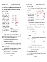
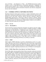
Pressed Wood Products
Pressed wood products originated in Europe in the
1960s as an alternative to wood furnishings, and en-
tered the U.S. market in the 1970s. Pressed wood prod-
ucts (Fig. 20-2) include particleboard, medium-density
fiberboard (MDF), hardwood plywood, chipboard, and
hardboard such as pegboard. These materials emit VOCs
including formaldehyde, ␣-pinene, xylenes, butanol,
butyl acetate, hexanal, and acetone.
Chemicals that emit VOCs are used in pressed wood
products to provide strength and moisture resistance.
Phenol-formaldehyde (PF) resins resist moisture degra-
dation, and are used in products destined for exterior
applications, as well as interior plywood and as bond-
ing for laminates on wood and steel surfaces. Urea-
formaldehyde (UF) resins are less expensive, but can only
be used for interior applications. Urea-formaldehyde
resins offgas 10 to 20 times as much as PF resins. They
are present in particleboard and in MDF, which has the
highest VOC content of the pressed wood products.
Pressed wood products are used extensively in res-
idential and commercial interiors projects. Worksurfaces
in offices account for 15 to 35 percent of the floor space.
Shelving adds another 10 to 20 percent, is usually lo-
cated near workers’ faces, and is exposed to air on both
upper and lower sides. In mobile homes, where pressed
wood products cover virtually every surface within a
confined space, formaldehyde is concentrated and poses
an increased threat to the health of occupants. Newly
constructed and furnished buildings present a greater
threat than older buildings, where the VOCs have had
Designing for Indoor Air Quality 125
Pl
y
wood
:
High-densit
y
overla
y
(HDO) pl
y
wood is
exterior pl
y
wood with
resin-fiber overla
y
on
both sides
.
Medium-densit
y
overla
y
(MDO)
pl
y
wood has phenolic
o
r mel
a
mine resin
overla
y
on one or both
si
d
es
.
P
a
rticle
boa
r
d
O
riente
d
strand
boa
r
d
Figure 20-2 Plywood, particle board, and oriented strand
board (OSB).
time to dissipate. High temperatures and humidity in-
crease the decomposition of VOCs, releasing more
formaldehyde during summer months.
Particle board, also called industrial board, is made
of chips and shavings of soft woods such as pine held
together with UF resins and glues, which constitute 6 to
10 percent of the product’s weight. Medium-density
fiberboard (MDF) combines wood pieces and chips
with UF adhesives and other chemicals comprising 8 to
14 percent of its weight. These are pressed together in a
hot hydraulic press. Medium-density fiberboard is used
for drawer fronts, cabinet doors, and furniture tops.
Hardwood plywood consists of thin sheets and ve-
neers of hardwoods like oak and maple, held together
by PF resins and glues that make up 2.5 percent of its
weight. Hardwood plywoods are used for cabinets and
furniture.
Chipboard is made of untreated wood fiber and pa-
per by-products pressed together with small amounts of
formaldehyde resins. Chipboard is used for the inner-
most layer of many modular office partitions. Hard-
board is used for pegboard and other inexpensive func-
tions. Wood fibers are pressed into a dense sheet while
applying heat to allow the natural resins to hold the
sheet together without glue. Relatively small amounts
of formaldehyde resins are then added along with other
chemicals to improve strength and moisture resistance.
Other pressed wood products, such as softwood ply-
wood and flake strand board or OSB, are produced for
exterior construction use and contain the dark, or red/
black-colored PF resin. Although formaldehyde is present
in both types of resins, pressed woods that contain PF
resin generally emit formaldehyde at considerably lower
rates than those containing UF resin. Where you are us-
ing extensive amounts of pressed wood products in an in-
terior, investigate whether PF resin products are an option.
Since 1985, HUD has permitted only the use of
plywood and particleboard that conform to specified
formaldehyde emission limits in the construction of pre-
fabricated and mobile homes. In the past, some of these
homes had elevated levels of formaldehyde because of
the large amount of high-emitting pressed wood prod-
ucts used in their construction and because of their rel-
atively small interior space. We should note here that
some natural wood products can also emit VOCs.
Flooring
Around 3 billion yards of carpet is sold each year in the
United States, 70 percent of which is replacement car-
pet. More than 2 billion yards of carpet ends up in land-
fills each year, where it remains largely intact for hun-
dreds of years.
Carpets may emit VOCs including formaldehyde,
toluene, benzene, and styrene, among others. The most
common emission is from 4-phenylcyclohexene (4-PC),
an odorous VOC from styrene-butadiene (SB) latex that
is used to bind the carpet fibers to the jute backings. Us-
ing heat fusion bonding for carpet backing eliminates
the high-VOC latex bond. Low emission carpets have fu-
sion bonded backing and use alternative fastening sys-
tems to eliminate latex and adhesives. Emissions from
4-PC may be initially high and tend to diminish quickly.
The amount of emissions varies with the carpet type.
Emissions of 4-PC have been linked to headaches, runny
eyes, mucous membrane irritation, dizziness, neurolog-
ical symptoms, and fatigue occurring after carpet in-
stallation. Carpets require three to four weeks for out-
gassing, with added ventilation and an increased air
exchange rate.
Carpet pads made of foamed plastic or sheet rub-
ber are high in VOCs. Felt pads, which use recycled syn-
thetic fibers or wool, or jute backings have low VOC
emissions. Cork, which is a quick-growing natural re-
source, can also be used. Tacking with nail strips rather
than gluing down carpet lowers emissions as well. If glue
is used, it should be water based or low-toxicity. Some
carpet adhesives emit xylenes, toluene, and a host of
other VOCs. Adhesives often emit VOCs for up to one
week.
Standard particleboard is often used as an under-
layment for carpet. It can be replaced with formalde-
hyde-free particleboard or exterior plywood. The best
option is low-density panels made from recycled paper.
Once a carpet is installed, it can continue to con-
tribute to IAQ problems. Carpets collect dust and parti-
cles. Vacuuming with plastic bags that retain microscopic
particles can contain these. The cleaning solutions used
on carpeting may include highly toxic chemicals.
The Carpet and Rug Institute (CRI) has developed
an Indoor Air Quality Testing Program. Environmen-
tally responsible carpet is identified with the CRI IAQ
label. New nylon formulations can be recycled into
useful products. Synthetic carpet can by made from re-
cycled post-consumer plastic, such as soda bottles.
DuPont and BASF both have developed nationwide
commercial carpet recycling programs. You can incor-
porate these programs into your projects by specifying
products that have the CRI IAQ label, and checking with
manufacturers about recycling.
Vinyl flooring emits VOCs. Soft vinyl used for sheet
flooring, which must bend into a roll, is made from petro-
chemical polymers with chemicals added for flexibility,
126 THERMAL COMFORT
and emits large amounts of VOCs for long periods of time.
Vinyl floor tiles emit formaldehyde, toluene, ketones,
xylenes, and many other VOCs. Vinyl sheets and tiles are
made of polyvinyl chloride (PVC) or a copolymer of vinyl
chloride, a binder of vinyl resins and plasticizers, fillers,
and pigments. Sheet vinyl also has a foam interlayer and
a backing of organic or other fiber or plastic.
Natural linoleum, made of linseed oil, cork, tree
resin, wood flour, clay pigments, and jute backing, is a
durable, attractive, and environmentally friendly alter-
native. The linseed oil is slowly oxidized and mixed with
pine resins into jelly-like slabs, then mixed with the cork
and wood flour and pigment granules. It is passed
through rollers onto the jute backing to form sheets,
and cured in heated drying rooms. Natural linoleum is
extremely long wearing, as the linseed oil continues to
oxidize even after curing, creating additional chemical
bonds. However, linoleum may emit VOCs including
toluene, hexanal, propanal, and butyl formiate when
initially installed.
Floor tile adhesives may emit toluene, benzene,
ethyl acetate, ethyl benzene, and styrene. Adhesives with
low VOCs are available.
The UF or polyurethane coatings on hardwood
flooring emit butyl acetate, ethyl acetate, ethyl benzene,
xylenes, and formaldehyde VOCs for a few days. Some
of the adhesives used with wood flooring also emit
VOCs.
Paints, Stains, and Other Coatings
The types of VOCs and the rate at which they are emit-
ted by paints depend on the chemical makeup, appli-
cation, indoor environment, and surface characteristics
of the substrate. Water-, oil-, or solvent-based paints all
emit aromatic hydrocarbons, alcohols, and aliphatic hy-
drocarbons. Latex- and solvent-based paints may give
off benzene, toluene, xylenes, ethanol, methanol, and
other VOCs. Paints can continue to emit VOCs even af-
ter drying, with water-borne paints emitting some chem-
icals even six months later.
Solvent-based paints contain hydrocarbons (HCs)
and other VOCs, which evaporate as the paint dries.
When the HCs react with sunlight and pollutants in the
air, they produce ozone. Solvent-based paints require
the use of hazardous solvents for thinning and cleanup.
Solvent-free paints are available in Europe.
Water-based paints, like latex paints, release much
lower VOCs than oil-based paints and varnishes. How-
ever, they may still be associated with irritation of mu-
cous membranes, resulting in headaches and both acute
and chronic respiratory affects. Latex paint may give off
VOCs, including butanone, ethyl benzene, and toluene.
Paints have information about VOCs on their labels. A
rating of less than 100 grams per liter (about 13 oz per
gallon) is good. Latex paints have biocides to prevent
fungus growth and spoilage. Latex paints with mercury-
based preservatives and antimildew agents can increase
the risk of liver and kidney damage, and if inhaled, can
affect the lungs and brain, but even so are less hazardous
than solvent-based paints.
Most varnishes are solvent-based urethanes. They
are highly noxious to handle, but stable when cured.
Water-based emulsion urethanes are low-emission, and
perform well. Solvents for mixing, removal, and appli-
cation of paints also emit VOCs. Paint stripper emits
methylene chloride.
When acid-cured or acid-catalyzed paints and coat-
ings are applied to pressed wood surfaces, they seal in
the emissions from the UF resin in the pressed wood,
and the outcome is fewer VOC emissions. Acid-cured
coatings do contain formaldehyde, acetone, toluene, and
butanol, but their ability to seal in formaldehyde out-
weighs the short-lived VOCs they emit. Emissions from
sprayed-on coatings decline by 90 to 96 percent during
the first 16 weeks after application, and brushed-on coat-
ings similarly decline 82 to 96 percent. Wood stains also
emit a variety of VOCs, as does polyurethane varnish.
Polymer oils for floor and cabinet finishes contain
formaldehyde gas. They remain toxic for several weeks
after application. If you must use them, select water-
based urethane, low toxic sealers, and wax finishes. Fur-
niture polish emits a range of VOCs as well.
Increasing ventilation alone may not be enough to
disperse VOCs during application of wet materials. Iso-
late the workspace from adjacent sections of the build-
ing. Block return registers, and open temporary local ex-
hausts like doors and windows. Increase ventilation to
other areas of the building, as well.
Wall Finishes
Wallcoverings vary in their impact on IAQ, depending
upon the materials from which they are made. Metal foils
have very low emissions, but present disposal problems.
Vinyl and vinyl-coated wallcoverings are less stable if
made of soft plastics, and have long outgassing times.
Vinyl wallcoverings emit vinyl chloride monomers and a
variety of other VOCs, but some studies indicate that they
are responsible for only negligible amounts of vinyl chlo-
ride emissions. Both metallic and vinyl wallcoverings
have highly polluting manufacturing processes.
Designing for Indoor Air Quality 127
Wallcoverings made of paper, plant fibers, silk, cot-
ton, and similar materials may also pose problems. Wall-
paper is usually made of four layers: a facing, an inter-
mediate layer, a backing, and the paste. They may contain
VOC-emitting inks, printing solvents, adhesives, binding
agents, finishing compounds, resins, glues, paper, vinyl
sheeting, or plasticizers. Most wallpaper now uses or-
ganic dyes and water-based inks that emit fewer VOCs.
Some wallpaper emits VOCs including methanol, etha-
nol, toluene, xylenes, and others, and may emit far more
formaldehyde than vinyl wallcoverings. Wallpaper may
remain above recommended exposure limits for one to
three days after installation. VOC emissions from all
types of wallcoverings drop after a few days.
The adhesives used for heavy wallcoverings can be
a problem. Wallpaper paste may emit a wide variety of
VOCs. Low-toxic adhesives are available. Lightweight pa-
pers can be applied with light, water-based glue.
Acoustic panels, tiles, and wallcoverings are typi-
cally made with a mineral fiber or fiberglass backing
with fabric coverings. They can be long-term sources of
formaldehyde and other gases, and tend to retain dust.
Ceiling panels of wood fibers, tapestries, or cork are bet-
ter choices, if permitted by the fire codes.
Wood paneling may be made of hardwood plywood,
MDF, solid hardwood, or UFFI simulated wall paneling.
Depending on its composition, wood paneling may emit
formaldehyde, acetone, benzene, and other VOCs, espe-
cially with higher temperatures and humidity.
Plastic or melamine panels can give off formalde-
hyde, phenol, aliphatic and aromatic HCs, ketones and
other VOCs. Polyvinyl chloride paneling emits phenol,
aliphatic and aromatic HCs, and glycol ethers and es-
ters. Plastic tiles contain polystyrene and UF resins.
When choosing a finish, consider where and how it
will be used, the client’s level of concern about avoiding
VOCs, whether proper ventilation will be provided be-
fore occupancy, and what alternatives exist that might
have less impact on the quality of the indoor air. It is not
always possible to completely avoid VOC emissions on
a project, but with care and resourcefulness, you can keep
high standards for appearance and maintenance, while
cutting pollutants and observing budget constraints.
Fabrics and Upholstered Furniture
The chemicals used to manufacture synthetic fabrics can
emit VOCs. Upholstered furniture coverings may emit
formaldehyde, chloroform, methyl chloroform, and
other VOCs. Polyurethane foam used in cushions and
upholstered furniture emits toluene di-isocyanate (TDI)
and phenol, but emissions decrease over time. Other
furniture components, such as pressed wood products,
adhesives, and formaldehyde resins, emit VOCs.
Natural and synthetic fabrics are often treated with
chemicals for strength, permanent press features, fire re-
sistance, water repellant properties, and soil repellency.
These treatments may emit VOCs. Formaldehyde is often
used as the carrier solvent in dying fabrics and in cross-
linking plant fibers to give rigidity to permanent press fab-
rics. Its use has decreased by up to 90 percent since 1975,
but it can still contribute substantially to VOC emissions
in a building. Draperies are often treated for soil, wrin-
kle, and fire resistance, and may emit VOCs as a result.
Modular Office Partitions
Although new office systems are less dependent on
fabric-covered cubicles, the majority of offices continue
to use these corporate workhorses. In fact, many offices
save money and avoid adding to landfills by purchas-
ing refurbished panels. Panels surround workers right at
breathing level, and add up to large amounts of square
footage. Since modular office partitions absorb pollut-
ants and later release them back into the air, long-term
use of older panels can add to their impact on IAQ.
Many modular office partitions consist of fabric at-
tached to fiberglass batt insulation, which is bonded to
a tempered hardboard or chipboard frame with vinyl ac-
etate adhesive. A metallic outer frame and support legs
complete the panel. Office partitions expose a great deal
of surface to the indoor air, totaling as much as twice
the floor surface area. The chipboard, hardboard, and
treated fabrics they contain have a high potential for
VOC emissions. The panels are in close proximity to of-
fice workers, and often nearly surround them, cutting off
air circulation, and keeping the VOCs near the workers.
Modular office partitions have the highest danger for
VOC emission right after installation. Manufacturers
may treat the panels with chemicals for soil and wrinkle
resistance just before wrapping and shipping, increasing
the amount of formaldehyde and other VOCs. Methyl-
ene chloride solvents are often used to clean panels dur-
ing manufacture and storage, and can be released when
the panels are unwrapped and installed.
Office partitions collect air contaminants, which can
be held in the fabric coverings and released later. Textured
fabric surfaces can absorb VOCs emitted by carpets, paints,
copying fluids, and tobacco smoke. Their absorption in-
creases with higher temperatures and decreased ventila-
tion, conditions that often occur in offices on weekends.
Because of their low thermal mass, office partitions emit
128 THERMAL COMFORT
surges of VOCs whenever there is a rapid change in air
temperature, as when the air-conditioning is turned back
on and ventilation increased on a Monday morning.
Some manufacturers will precondition furnishings,
including office partitions, during the storage, shipping,
and installation process. Since most of the outgassing
occurs in the first few hours, days, or weeks after removal
of the packaging, VOCs can be eliminated from the site
by unpacking and exposing materials before bringing
them into the building.
Plastics
Technically, plastics are not solids, but viscoelastic fluids,
and they evaporate. The plastics used to make wallcover-
ings, carpets, padding, plumbing pipes, and electric wires
and their insulation emit toxic chemicals. These include
nitrogen oxide, cyanide, and acid gases. Fumes can be pro-
duced by polymers or by additives used as colorants or
plasticizers. Plasticizers soften plastics, making them less
stable. Polyvinyl chloride plastics are safe to use, but their
manufacturing process is hazardous and produces health
risks. They also emit toxic fumes in fires. Most plastic lam-
inates have very low toxicity levels. They are made from
petroleum. Other chemicals have replaced chlorofluoro-
carbons (CFCs) for upholstery foams and insulating
foams. One type of replacement, hydrochlorofluorocar-
bons (HCFCs), contributes to the greenhouse effect.
Plastics last for hundreds of years, and pollute both
the land and the marine environment. The best solu-
tion for their disposal is recycling, which also saves raw
materials and energy. Recycled plastics are used for out-
door furniture, floor tiles, carpets, and an increasing
number of other products.
Adhesives, Sealants, and Coatings
Most adhesives used in the building process are solvent-
based with toluene, xylene, acetone, and other haz-
ardous solvents. Water-based adhesives are safer, but still
contain some solvents, including benzene, toluene, ace-
tone, and xylenes. The lowest toxicity is found in water-
soluble casein or plain white glue.
Caulking compounds used to seal cracks and seams
may emit VOCs. Silicone caulking is very safe and sta-
ble. Latex caulking is safe once cured, but some types
produce odors for weeks after installation from a variety
of VOCs including benzene and toluene. Uncured rub-
ber caulkings, such as butyl caulk, acoustical sealant, and
polysulfide caulk, are harmful, and may emit formalde-
hyde, acetic acid, toluene, xylenes, and other VOCs.
The process of painting or plating furniture can cre-
ate air and water pollution and toxic waste. Coating pro-
cesses are less polluting and safer. Metals can be coated
with powder coating. Polymer coating has replaced cad-
mium plating, which produced air and water pollution.
Check specifications for metal tables and chairs to see
how they are coated.
MATERIALS SAFETY
DATA SHEETS
Manufacturers of products that have health and safety
implications are required to provide a summary of the
chemical composition of the material including health
risks, flammability, handling, and storage precautions.
Materials Safety Data Sheets (MSDS) list all chemical
constituents that make up a minimum of 1 percent of
the material and are not proprietary. The sheets do not
predict VOC emission rates, and you have to make as-
sumptions about whether higher percentages of a chem-
ical imply higher outgassing rates. It is best to require
MSDS for all products and materials used indoors. If
questionable components are present, you may have to
obtain additional information on chemical formula-
tions, storage, drying times, and airing procedures.
Some definitions are useful to decipher the infor-
mation in an MSDS. The accepted toxicity for a haz-
ardous material is referred to as its threshold limit value
(TLV). The lower the TLV, the more toxic the material.
The allowable exposure limit over a working day is
called the time weighted average (TWA). The lower the
TWA, the more toxic the material. The lethal dose, 50
percent (LD50) is the dose at which, when ingested, half
of tested lab animals will die. (The U.S. government has
recently changed its policy to permit other tests that do
not result in high mortality for lab animals.) The lower
the LD50, the more toxic the material. The total volatile
organic content (TVOC) is the volume of the product
that will evaporate over time. High TVOC adds more in-
door air pollution.
INDOOR AIR
QUALITY EQUIPMENT
Once the sources of IAQ problems have been removed
or isolated wherever possible, increased ventilation and
improved air filtration are usually the next most practi-
cal measures. The most expensive part of running a busi-
Designing for Indoor Air Quality 129
ness is the cost of employing people. The projected
health and productivity benefits of increasing ventila-
tion for a large building are many times the cost. Im-
proving air filtration also produces great benefits for
each dollar spent.
Let’s look at some of the building system compo-
nents that address IAQ issues. We discuss these in more
detail later, so consider this an introduction to some of
the terminology and design considerations.
Building codes specify the amount of ventilation re-
quired for specific purposes and occupancies in terms of
air change per hour, or in cubic feet per minute (cfm)
per person. ASHRAE Standard 62-1989, Ventilation for
Acceptable Indoor Air Quality, recommends 15 to 20 cfm
of outdoor air per person for most applications. The me-
chanical engineer will use the appropriate figure to de-
termine what equipment is needed for a specific project.
Increasing ventilation for improved air quality must
strike a balance with energy conservation. Energy con-
servation efforts have resulted in reduced air circulation
rates in many central air-handling systems. Fewer fans
use less power, but distribution is poorer, and the air
mix within individual spaces suffers. Individual space
air-filtering equipment provides a higher circulation rate
and a proper air mix. Each unit has a fan that operates
with or without the central HVAC fan, and circulates air
six to ten times per hour. The air is then ducted to dif-
fusers, from which it circulates across the space to re-
turn air intakes on the opposite side of the room.
There are a number of ways that good ventilation
can be assured while controlling heat loss. Heat ex-
changers recover heat from air that is being exhausted
and transfer it to makeup outside air coming into the
building, saving heating energy. By tracking occupancy
patterns in the building, ventilation can be tailored to
the number of people in the building at any one time.
Opening outside air dampers for one hour after peo-
ple leave an area for the day, where possible, can dilute
large volumes of room air and dissipate collected
contaminants.
Engineers find that it is easiest to get good IAQ with
a heating and cooling system using forced air motion
(fans and blowers), with some filtering equipment built
into the air-handling equipment. Separate air-cleaning
systems are commonly used with radiant heating systems.
Cooling systems can use economizer cycles at night, when
they vent warm indoor air to the outside, and bring in
cooler outdoor air for overnight cooling. Evaporative
cooling systems use a continuous flow of outdoor air
where you want to add humidity to the indoor air.
The general types of technologies used by air clean-
ers include mechanical filters, electronic air cleaners,
and hybrid filters for the capture of particles, plus gas
phase filters to control odors. Air cleaners that operate
by chemical process, such as ozonation, also exist. The
selection of a type of air filter should depend on the in-
tended use of the filter, as explained below.
Air filters protect the HVAC equipment and its com-
ponents and the furnishings and decor of occupied
spaces, and protect the general well-being of residents.
They reduce housekeeping and building maintenance,
as well as furnace and heating equipment fire hazards.
The lower efficiency filters generally used in central
HVAC systems will usually cover all of these functions
except protecting the health of the occupants, for which
much higher performance filtration is required. It may
not always be possible to install such equipment in
older existing environmental systems, so self-contained
portable room air cleaners must sometimes be used to
obtain sufficiently high levels of filtration effectiveness.
Residential Air Cleaners
Until recently, small, inexpensive, tabletop appliance-
type air cleaners have been quite popular for residential
use. They generally contain small panels of dry, loosely
packed, low-density fiber filters upstream of a high-
velocity fan. Tabletop units may also consist of a fan
and an electronic or other type of filter. Small tabletop
units generally have limited airflow and inefficient
panel filters. Most tests have shown these tabletop units
to be relatively ineffective. The combination of low fil-
ter efficiency and low airflow in these units causes them
to provide essentially no cleaning when assessed for im-
pact on the air of the entire room. Some of the units
produce harmful levels of ozone and do not have au-
tomatic controls to limit ozone output.
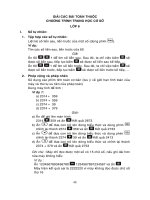
Another major type of residential air cleaner is the
larger but still portable device designed to clean the air
in a specific size room (Fig. 20-3). Due to their larger
and more effective filters or collecting plates, these
portable room air cleaners are considerably more effec-
tive in cleaning the air in a room than the tabletop units
and have become increasingly popular in the past sev-
eral years. Room-size air cleaners are generally utilized
when continuous, localized air cleaning is necessary.
Most units may be moved from room to room to re-
duce pollutant concentration levels as needed. As with
tabletop units, room units incorporate a variety of air-
cleaning technologies.
Air-cleaning systems can also be installed in the cen-
tral heating or air-conditioning systems of a residence
or in an HVAC system. These units are commonly re-
130 THERMAL COMFORT
ferred to as in-duct units, although they are not actually
located in the distribution ductwork, but rather in un-
ducted return air grilles or ducted return air plenums.
These central filtration systems provide building-wide
air cleaning and, by continuously recirculating building
air through the unit, can potentially clean the air
throughout the entire air-handling system, ductwork,
and rooms. However, with these types of units, the
HVAC fan must be in constant operation for air clean-
ing to occur, since the airborne contaminants must be
captured and carried back to the centralized filter for
capture and retention. Thus central filtration systems
must be operated with the fan on for constant air move-
ment through the HVAC system. Generally, residential
HVAC systems run their fans only intermittently to
maintain a comfortable indoor temperature. Research
indicates that a highly efficient room unit will be more
effective at removing pollutants in the room where it is
located than a central filtration system.
Both outside air and recycled air must be filtered.
Inadequate filtration is a result of low-efficiency filters,
improper installation, or torn, clogged, or otherwise in-
effective filters. Ductwork is often installed without any
provision for access or cleaning, leading to a massive
buildup of contamination that can spread to building
occupants. Poor maintenance in the ducts puts even
more demands on the filters. It is best to remove pol-
lutants at the source, and therefore ASHRAE recom-
mends dust collectors at the source rather than filters
for dusty areas. For example, the maintenance workshop
in a hotel would have a vacuum that removed sawdust
immediately from the worktable, rather than a filter in
the air-conditioning system that would allow the dust
to spread throughout the area.
If the sources of allergy problems are present in a
residence, air cleaning alone has not been proven ef-
fective at reducing airborne allergen-containing particles
to levels at which no adverse effects are anticipated. Cats,
for example, generally shed allergen at a much greater
rate than air cleaners can effect removal. Dust mites ex-
crete allergens in fecal particles within the carpet or the
bedding, where air cleaners are ineffective. For individ-
uals sensitive to dust mite allergen, the use of imper-
meable mattress coverings appears to be as effective as
the use of an air-cleaning unit above the bed. Source
control should always be the first choice for allergen
control in residences.
If the choice is made to use an air cleaner, choose
one that ensures high efficiency over an extended pe-
riod of time and does not produce ozone levels above
0.05 parts per million (ppm).
Mechanical Filters
Mechanical filters may be used in central filtration sys-
tems as well as in portable units using a fan to force air
through the filter. Mechanical filters capture particles by
straining larger and then smaller particles out of the
airstream thorough increasingly smaller openings in
the filter pack. Very small submicron-sized particles are
captured by being drawn toward the surfaces of the fil-
tration medium, where they are held by static electric
charges. This is the factor responsible for the effective-
ness of the highest efficiency mechanical filters’ removal
of submicron-sized particles. There are three major types
of mechanical filters: panel or flat filters, pleated filters,
and high-efficiency particulate air (HEPA) filters.
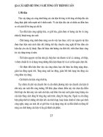
Flat or panel filters (Fig. 20-4) usually contain a low
packing density fibrous medium that can be either dry
or coated with a sticky substance, such as oil, so that
particles adhere to it. Less-expensive lower efficiency fil-
ters that employ woven fiberglass strands to catch par-
ticles restrict airflow less, so smaller fans and less en-
ergy are needed. The typical, low-efficiency furnace filter
in many residential HVAC systems is a flat filter, 13 to
25 mm (
ᎏ
1
2
ᎏ
–1 in.) thick, that is efficient in collecting large
particles, but removes only between 10 and 60 percent
of total particles, and lets most smaller, respirable-size
particles through.
Older buildings were designed with only crude
panel filters in HVAC equipment. Engineers now also
use a combination of high-efficiency particle filters and
adsorption filters to achieve high IAQ. Panel filters are
Designing for Indoor Air Quality 131
Figure 20-3 Portable air cleaner.
placed ahead of the HVAC unit’s fan (upstream), and
the high-efficiency systems are located downstream
from the HVAC’s cooling units and drain pans. This way,
microbiological contaminants in wet components of the
system are removed before they are distributed with the
air through the entire building.
Not all pollutants can be removed by filters. Large
sized particles are the easiest to remove, but smaller par-
ticles may be the most dangerous. Panel filters come
with HVAC equipment, and are designed primarily to
protect fans from large particles of lint and dust, not for
proper air cleaning. Standard commercial grade filters
remove 75 to 85 percent of particles from the air.
Media filters use much finer fibers. However, any
increase in filter density significantly increases resistance
to airflow, slowing down the air flowing through the fil-
ter. Media filters are around 90 percent efficient. They
are usually a minimum of 15 cm (6 in.) deep, and have
a minimum life cycle of six months. Filters, and espe-
cially media filters, require regular maintenance. If
blocked, they can damage HVAC equipment, so they
must be replaced frequently. Filters for large units can
cover an entire wall in a room-size air-handler plenum.
The most effective approach to increasing effective-
ness in a filter is to extend the surface area by pleating
the filter medium. This slows down the airflow velocity
through the filter and decreases overall resistance to air-
flow to reduce the drop in pressure. Pleated filters use
highly efficient filter paper in pleats within a frame.
Pleating of filter media increases the total filtering area
and extends the useful life of the filter. The efficiency of
pleated media filters is much higher than for other dry-
type filters.
High-efficiency particulate air filters provide the best
protection. Such HEPA filters were originally developed
during World War II to prevent discharge of radioactive
particles from nuclear reactor facility exhausts. They are
now found in special air cleaners for very polluted en-
vironments, and for spaces that demand the highest
quality IAQ. High-efficiency filters are used in hospitals
and laboratories, as well as in portable residential air
cleaners. They are generally made from a single sheet of
water repellent fiber that’s pleated to provide more sur-
face area with which to catch particles. The filter is made
of tiny glass fibers in a thickness and texture very simi-
lar to blotter paper. To qualify as a HEPA filter, the filter
must allow no more than three particles out of 10,000
(including smaller respirable particles) to penetrate the
filtration media, a minimum particle removal efficiency
of 99.97 percent. Because they are more densely woven
than other filters, HEPA filters require larger and more
energy-intensive fans, making them more expensive and
noisier. Consequently, HEPA filters are generally reserved
for hospital operating rooms, manufacturing clean
rooms (for example, where computer chips are made),
and other especially sensitive places. HEPA filters are gen-
erally not applied to central residential HVAC systems
due to their size and horsepower requirements. They
need a powerful fan, leading to increased energy costs.
Replacement filters range from $50 to $100, but last up
to five years when used with a prefilter.
Similar HEPA-type filters with less efficient filter pa-
per may have 55 percent efficiencies. These filters, which
are still very good when compared to conventional
panel type and even pleated filters, have higher airflow,
lower efficiency, and lower cost than their original
version.
In summary, there is little reason to use inexpensive
tabletop, appliance-type air cleaners, regardless of the
technology they employ. In general, high-efficiency par-
ticle collection requires larger filters or electronic air
cleaners.
Electronic Air Cleaners
Electronic filters, generally marketed as electronic air
cleaners, employ an electrical field to trap particles. Like
mechanical filters, they may be installed in central fil-
tration systems as well as in portable units with fans.
Electronic air cleaners require less maintenance than
systems with filters, but produce ozone. Air rushing
through a mechanical filter produces static electricity.
132 THERMAL COMFORT
D
u
c
t
P
a
nel
Fil
ter
Airfl
ow
Figure 20-4 Dry mat panel air filter.
Larger particles cling to the filter, which loses efficiency
with more humidity and higher air velocity.
The simplest form of electronic air cleaner is the
negative ion generator. A basic electronic air cleaner uses
static charges to remove particles from indoor air. They
operate by charging the particles in a room, which be-
come attracted to and deposit on walls, floors, table-
tops, curtains, or occupants, from which they must then
be cleaned up.
More advanced units are designed to reduce soiling
in a room. They generate negative ions within a space
through which air flows, causing particles entrained in
the air to become charged. The charged particles are then
drawn back into the cleaner by a fan, where they are
collected on a charged panel filter. In other ionizers, a
stream of negative ions is generated in pulses, and neg-
atively charged particles are drawn back to the ionizer.
While personal air purifiers using this technology can
have a beneficial effect on airborne particles, they also
require frequent maintenance and cleaning.
Electrostatic precipitators are the more common
type of electronic air cleaner. They employ a one-stage
or a two-stage design for particle collection. In the less
expensive but less effective single-stage design, a charged
medium acts to both charge and collect airborne parti-
cles. This polarizes particles, which then cling to the fil-
ter material. If the field is not strong enough, many par-
ticles fail to be polarized and pass through.
In a two-stage electronic air cleaner, dirty air passes
between the ionizing wires of a high-voltage power sup-
ply. Electrons are stripped from the particles in the air,
leaving the particles with a positive charge (ions). The
ionized particles then pass between closely spaced col-
lector plates with opposing charges. They are repelled
by the positive plates and attracted to the negative ones,
where they are collected.
The advantages of electronic filters are that they gen-
erally have low energy costs because they don’t create a
lot of resistance. The airflow through the units remains
constant, and the precipitating cell is reusable, avoiding
long-term filter replacement costs. The major disadvan-
tages are that they become less efficient with use, pre-
cipitating cells require frequent cleaning, and they can
produce ozone, either as a by-product of use or inten-
tionally. Those installed into HVAC systems have a rel-
atively high initial cost, including expensive installation.
Hybrid Filters
Hybrid filters incorporate two or more of the filter con-
trol technologies discussed above. Some combine me-
chanical filters with an electrostatic precipitator or an
ion generator in an integrated system or single self-
contained device.
Gas Phase Filters
Compared to particulate control, gas phase pollution
control is a relatively new and complex field that seeks
to remove gases and associated odors. Two types of gas
phase capture and control filters are chemisorption and
physical adsorption.
Chemisorption occurs when the active material at-
tracts gas molecules onto its surface, where a bond is
formed between the surface and the molecule. The ma-
terial that absorbs the pollutant is changed by the in-
teraction, and requires replacement regularly.
Physical adsorption filters are used to remove gases
by physically attracting and adhering a gas to the sur-
face of a solid, usually activated carbon in the case of
air filtration. The process is similar to the action of a
magnet attracting iron filings. The pollutant doesn’t
bond with the solid, which can thus be reused. Once
the gas is on the activated carbon, it moves down into
the carbon particle, eventually condensing into a liquid.
Activated carbon adsorbs some gaseous indoor air
pollutants, especially VOCs, sulfur dioxide, and ozone,
but it does not efficiently adsorb volatile, low molecu-
lar weight gases such as formaldehyde and ammonia.
Although relatively small quantities of activated char-
coal reduce odors in residences, many pollutants affect
health at levels below odor thresholds.
Some recently developed systems use more active
particles of carbon, permanganate alumina, or zeolite
that are incorporated into a fabric mat. Other adsorp-
tion filters use porous pellets impregnated with active
chemicals like potassium permanganate, which react
with contaminants and reduce their harmful effects.
All adsorbents require frequent maintenance, and
may reemit trapped pollutants when saturated. High-
quality adsorption filters are designed to be used 24
hours per day, seven days a week, for six months, at
which time they must be regenerated or replaced. While
effective, these filters only capture a small percentage of
certain specific gases and vapors.
Air Washers
Air washers are sometimes used to control humidity
and bacterial growth. In some large ventilation sys-
tems, air is scrubbed with jets of water that remove
Designing for Indoor Air Quality 133
dust from the air. If the equipment is not well main-
tained, the moisture within the air washer can be a
source of pollution.
Ozone Generators
Although it is harmful in high concentrations, ozone
may be used to reduce indoor pollutants. When the two
molecules that make up oxygen are broken down with
an electrical discharge, the molecules end up coming
back together in groups of three to form ozone mole-
cules. Once released into the air, ozone actively seeks
out pollutants, attaching itself to a wide range of con-
taminants including chemical gases, bacteria, mold, and
mildew, and destroying them by cracking their molecu-
lar membranes. Because ozone has a very short life
span—between 20 and 30 minutes—it’s easy to avoid
achieving the high concentrations that can damage peo-
ple’s health. However, some experts, including the EPA,
do not agree that ozone is an effective air treatment.
Ozone generators use a chemical modification pro-
cess instead of mechanical or electronic filters. Ozone
has been used in water purification since 1893, and is
used in cooling towers to control contaminants without
negative side effects. Ozone introduced into the air-
stream can help control microbial growth and odors in
uses such as meat storage or in fire- and flood-damaged
buildings where humans are not exposed.
Appliance-sized ozone generating units have typi-
cally been marketed in the United States as air cleaners.
However, the high concentration levels required for con-
taminant control are in conflict with potential health ef-
fects as established by the National Institute of Occupa-
tional Safety and Health, the EPA, and the U.S. Food and
Drug Administration. Because of the documented health
dangers of ozone, especially for individuals with asthma,
and the lack of evidence for its ability to effectively clean
the air at low concentrations, the American Lung Associ-
ation suggests that ozone generators not be used.
Ultraviolet Light
Ultraviolet (UV) light rays kill germs and destroy the
DNA structure of viruses, bacteria, and fungi. These are
the same rays that emanate from the sun and kill
microorganisms on laundry on a clothesline. Ultravio-
let light has been used for years in hospitals to sanitize
rooms and equipment, and is also effective in elimi-
nating many odors and controlling the spread of cold
and flu viruses. However, it can be more expensive than
other purification techniques.
Ultraviolet light is installed within HVAC systems
to control fungi, bacteria, and viruses, helping cooling
coils and drain pans stay cleaner. It works best at room
temperatures and warmer, and with UV-reflective alu-
minum duct interiors. The lamps used for UV light take
up very little space within the ductwork, and no ozone
or chemicals are produced. Tube life is 5000 to 7500
hours, so if the tubes are on all the time, they need ac-
cess for replacement in less than a year.
Ultraviolet lamps may also be installed directly in
rooms, such as kitchens, sickrooms, or overcrowded
dwellings. The lamps must be mounted high in the
room and shielded from sight, as they can damage the
eyes and skin. Some personal air purifiers also use UV
light. Laboratory fume hoods and other IAQ equipment
use a UV lamp focused on a catalyst in the presence of
water vapor. This process destroys airborne microor-
ganisms and VOCs better than chlorine.
The National Renewable Energy Laboratory is de-
veloping a process for using UV to control VOCs. Pol-
luted air is bombarded with UV in the presence of spe-
cial catalysts. The process quickly breaks down cigarette
smoke, formaldehyde, and toluene into molecules of
water and carbon dioxide.
Future Developments in
Testing and Filters
Filter strips precoated with testing compounds that will
affordably detect harmful pollutants in specific loca-
tions are being developed. Hanging these strips in a
building may eliminate the need for expensive surveys
and tests by air quality consultants.
Compounds that are specifically designed to target
particular gases such as formaldehyde and carbon
monoxide are also under development. When sprayed
onto lower efficiency and carbon-activated filters, these
compounds will extract the offending gases from the air
through adsorption. By combining test strips with these
new compounds, IAQ problems will be targeted more
easily.
Central Cleaning Systems
Central cleaning systems have been used in homes
and commercial buildings for years. They are essentially
built-in vacuum cleaners with powerful motors. As such,
134 THERMAL COMFORT
they can be used to trap dirt and dust inside the power
unit equipment and away from rooms where people live
and work, or they can be vented outdoors, decreasing
exposure for people with dust allergies. The power unit
is usually installed in a utility room, basement, or
garage. Tubing running under the floor or in the attic
connects through the walls to unobtrusive inlets placed
conveniently throughout the building. When it’s time
to vacuum, a long flexible hose is inserted into an inlet
and the system turns on automatically. The noise is kept
at the remote location of the power unit. Most power
units operate on a dedicated 15-A normal residential
electrical circuit, but some larger units may require heav-
ier wiring. Systems come with a variety of hoses and
brushes. Installation is simplest in new construction.
With a day or two’s work, a builder, a plumber, a sys-
tem dealer, or even a building owner with some knowl-
edge of electricity, can install a system. Central cleaning
systems are commonly found in commercial office
buildings and restaurants.
Odor Control
We perceive an odor most when we first encounter it,
and then the odor gradually fades in our awareness. This
is why you notice an odor more when first entering a
room, but later become unaware of it. Typical office
odors include tobacco smoke, body odor, grooming
products (perfumes), copy machines, cleaning fluids,
and outgassing from materials such as carpets, furniture,
and construction materials. Testing equipment doesn’t
detect odors as well as your nose, so it may be difficult
to test for specific sources of odors.
You can cut down on odors by increasing the rate
of outdoor ventilation. In order to control human body
odor, engineers recommend that three to four liters per
second or L/s (6–9 cfm) of outdoor air per occupant
should be added to the space. Where smoking occurs,
7 to 14 L/s (15–30 cfm) per person is required, which
is bad for energy conservation in hot and cold weath-
ers. This is yet another cost to society from smoking.
Designing for Indoor Air Quality 135
Before the invention of mechanical ventilation, the com-
mon high ceilings in buildings created a large volume of
indoor air that diluted odors and carbon dioxide. Fresh
air was provided by infiltration, the accidental leakage
of air through cracks in the building, which along with
operable windows created a steady exchange of air with
the outdoors. The high ceilings of older auditoriums har-
bor a reserve where fresh air can build up when the build-
ing is unoccupied between performances.
NATURAL VENTILATION
Natural ventilation requires a source of air of an ac-
ceptable temperature, moisture content, and cleanliness,
and a force—usually wind or convection—to move the
air through the inhabited spaces of a building. Air flows
through a building because it moves from higher pres-
sure to lower pressure areas. Controls are provided for
the volume, velocity, and direction of the airflow. Fi-
nally, the contaminated air must be cleaned and reused
or exhausted from the building.
The simplest system for getting fresh air into a build-
ing uses outdoor air for its source and wind for its power.
Wind creates local areas of high pressure on the wind-
ward side of the building, and low pressure on the lee-
ward side. Fresh air infiltrates the building on the wind-
ward side through cracks and seams. On the opposite
side of the building, where pressure is lower, stale in-
doors air leaks back outside. Wind-powered ventilation
is most efficient if there are windows on at least two
sides of a room, preferably opposite each other. The pro-
cess of infiltration can be slow in a tightly constructed
building. Loose-fitting doors and windows result in
buildings with drafty rooms and wasted energy.
Depending on the leakage openings in the building
exterior, the wind can affect pressure relationships
within and between rooms. The building should be de-
signed to take advantage of the prevailing winds in the
warmest seasons when it is sited and when the interior
is laid out.
Very leaky spaces have two to three air changes or
more per hour. Even when doors and windows are
weather-stripped and construction seams are sealed air-
tight, about one-half to one air change per hour will oc-
cur, but this may be useful for the minimum air re-
placement needed in a small building. Weather-stripping
materials generally have a lifespan of less than ten years,
and need to be replaced before they wear out.
In convective ventilation, differences in the density
of warmer and cooler air create the differences in pres-
21
Chapter
Ventilation
136
sure that move the air. Convective ventilation uses the
principle that hot air rises, known as the stack effect.
The warm air inside the building rises and exits near the
building’s top. Cool air infiltrates at lower levels. The
stack effect works best when the intakes are as low as
possible and the height of the stack is as great as possi-
ble. The stack effect is not noticeable in buildings less
than five stories or about 30.5 meters (100 ft) tall. In
cold weather, fans can be run in reverse to push warm
air back down into the building. Fire protection codes
restrict air interaction between floors of high-rises, re-
ducing or eliminating the stack effect. To depend on
convective forces alone for natural ventilation, you need
relatively large openings. Insect screens keep out bugs,
birds, and small animals, and admit light and air, but
cut down on the amount of airflow. Systems using only
convective forces are not usually as strong as those de-
pending on the wind.
The ventilation rate is measured in liters per second
(L/s) or in cubic feet per minute (cfm). It takes only very
small amounts of air to provide enough oxygen for us to
breathe. The recommended ventilation rate for offices is
9.44 L/s (20 cfm) of outside air for each occupant in non-
smoking areas. About a quarter of this amount is required
to dilute carbon dioxide from human respiration, while
another quarter counteracts body odors. The remainder
dilutes emissions from interior building materials and of-
fice equipment. This works out to slightly more than one
air change per hour in an office with an eight-foot high
ceiling. Lower ceilings create greater densities of people
per volume, and require higher rates of ventilation.
Especially high rates of air replacement are needed
in buildings housing heat- and odor-producing activi-
ties. Restaurant kitchens, gym locker rooms, bars, and
auditoriums require extra ventilation. Lower rates are
permissible for residences, lightly occupied offices, ware-
houses, and light manufacturing plants.
Using natural ventilation helps keep a building cool
in hot weather and supplies fresh air without resorting
to energy-dependent machines. However, in cold cli-
mates energy loss through buildings that leak warm air
can offset the benefits of natural cooling. Careful build-
ing design can maximize the benefits of natural venti-
lation while avoiding energy waste.
Attic ventilation is the traditional way of control-
ling temperature and moisture in an attic. Ventilating
an attic reduces temperature swings. It makes the build-
ing more comfortable during hot weather and reduces
the cost of mechanical air conditioning. William Rose,
with the Building Research Council at the University of
Illinois, has been conducting some of the first research
into how and why attic ventilation works.
Thermal buoyancy—the rising of warm air—is a
major cause of air leakage from a building’s living space
to the attic, but Rose’s research shows that wind is the
major force driving air exchange between an attic and
the outdoors, and that the role of thermal buoyancy in
diluting attic air with outdoor air is negligible. Gener-
ally, we assume that warmer air rises and escapes from
high vents in an attic, while cooler air enters in lower
vents. Some ridge vents at the roof’s peak may in fact
allow air to blow in one side and out the other, with-
out drawing much air from the attic. Ridge vents with
baffles may create better suction to draw air out.
Soffit vents, which are located in the roof’s over-
hang, work well as inlets and outlets. There’s less prob-
lem with rain and snow getting in, because soffit vents
point downward. Soffit vents should always be installed
whenever there are high vents on ridges or gables, which
pull air out of the attic. Without soffit vents, makeup
air would be drawn through the ceiling below, which
increases heat loss and adds moisture to the attic.
To get maximum protection, soffit vents should be
located as far out from the wall as possible, so that rain
or snow blowing into the soffit is less likely to soak the
insulation or drywall. They should be distributed evenly
around the attic, including corners. At least half of the
vent area should be low on the roof. The net free area
(NFA), which is stamped on the vents, indicates resis-
tance, with higher numbers indicating less resistance
and better airflow.
Rose’s research shows that a ventilated attic is
slightly warmer on a clear, cold night than an unvented
attic. In winter, venting maintains uniform roof sheath-
ing temperature, which reduces the likelihood that ice
dams will form. Without good ventilation, warm spots
form near the eaves that melt snow against the roof shin-
gles, which can later refreeze into an ice dam. Water runs
down until it is over the eaves, where it refreezes. This
ice then builds up and causes the water collecting above
it to seep in under the shingles and into the eaves or
the house. More melting snow can build up behind the
ice dam and damage the building.
Chronic ice dam problems often lead to the use of
electric heater cables or snow shoveling to attempt to
clear the snow out of the way. Using self-stick rubber-
ized water and ice membranes plus roof ventilation can
prevent ice dams.
Warm air rising up through plumbing, electrical,
and other penetrations into the attic will also heat the
roof sheathing. Adding ventilation without sealing air
leaks into the attic can actually increase the amount of
air leaking from the house, wasting valuable heat and
potentially making ice dams worse. Air leaking out of
Ventilation 137
air handlers and ducts, and heat leaving the system by
conduction can be among the largest causes of heat loss
and ice damming.
Heated air escaping into the roof not only contrib-
utes to ice dams and heat loss, it is also the primary
means for moisture to get into attic or roof framing,
where it can condense and cause mold, mildew, and
structural damage to the roof. Surprisingly, much of the
moisture that rises through openings around plumbing,
ducts, and wires comes as water vapor in air vented from
crawlspaces. Once in the attic, the air cools, allowing its
water vapor to condense on roof sheathing. Ventilation
alone can’t take care of moisture in the attic. Keeping
dampness out of the building—especially out of the
basement and crawlspace—helps protect against con-
densation and mildew in the attic. An airtight ceiling is
also important.
Installing rigid insulation in the eaves (the project-
ing overhang at the lower edge of a roof) reduces heat
loss in the eave area. Another option is to change the
framing detail to one that leaves more room between
the top plate and the rafter. Cardboard or foam baffles
precut to fit 16- or 24-in. on center framing can elimi-
nate wind blowing across insulation.
Eliminate leaks that allow heated air to escape into
the attic at top plates, wiring penetrations, plumbing
vents, and chimney and duct chases. Recessed lights are
responsible for significant heat loss; be sure to use fixtures
rated for insulation contact (IC rated) and air tightness.
Heating, ventilating, and air-conditioning (HVAC)
equipment and ductwork in attics will waste leaking air.
If there is no alternative, all ducts should be sealed tightly
and run close to the ceiling, buried in loose fill insula-
tion to the equivalent R-value of the attic insulation.
Once you eliminate the heat loss in the attic, there
is little driving force to pull air through the vents.
However, code-required ventilation openings in attics
and cathedral ceilings should be installed as a backup
measure.
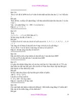
Though now valued for style, symbolism, and at-
tractiveness, cupolas (Fig. 21-1) represented early air-
conditioning. The cupola was a high point in which the
hottest air in the house could collect and from which it
could escape outside because hot air’s natural buoyancy
causes it to rise. Cooler air was in turn drawn into the
house through the open windows below. This stack ef-
fect becomes most effective when there is a good source
of hot air to accelerate the flow, as from an attic. When
the wind was blowing briskly through the cupola, an
updraft throughout the house pulled cooler air in
through the windows. However, without at least a little
wind, you didn’t get much ventilation. Using a cupola
or ridge vents along the top of the roof will cool only
the attic if there is an air and vapor barrier and blanket
of insulation isolating the attic from the house below,
as is customary today.
Roof windows, also called operable or venting sky-
lights (Fig. 21-2), can create the same updraft through-
out the house as an old-fashioned cupola. When shaded
to keep direct sunlight out, they are one of the best nat-
ural ventilating devices available. However, their value
for cooling alone does not compensate for their initial
cost. Roof windows also allow moisture to escape from
kitchens, baths, laundry rooms, and pool enclosures.
138 THERMAL COMFORT
Figure 21-2 Roof window.
Figure 21-1 Cupola.
Roof windows are available with remote controls
and rain sensors. Skylights can be prewired for sun-
screening accessories, including sun-blocking shades,
pleated shades, venetian blinds, or roller shades. Exte-
rior awnings block up to 40 percent more heat than in-
terior shades, and are available with manual and auto-
matic controls. ENERGY STAR® skylights use low-emissivity
(low-e) glass coatings, warm edge technology that en-
sures that the areas around the frames don’t reduce the
insulating properties of the glazing, and energy-efficient
blinds that improve overall energy efficiency.
Roof ventilators also increase natural ventilation.
Some roof ventilators are spun by the wind, drawing air
from the room below. Some rely on convective flow,
while some create low-pressure areas that are then filled
with interior air. Wind gravity or turbine ventilators cre-
ate suction when wind blows across the top of a stack,
pulling air up and out of the building. Roof ventilators
require control dampers to change the size of the open-
ing as necessary.
Doors should not be relied upon for essential build-
ing ventilation unless they are equipped with a holder
set at the desired angle. An ordinary door can’t control
the amount of air that flows past it.
In residences, ventilation is tied to the quantity of
exterior windows and the amount of natural ventilation
they supply. If the bathroom does not have a window,
it is required to have a fan with a duct leading directly
to the exterior. A window provides not only ventilation,
but also daylight and possibly a room-expanding view.
A percentage of the windows in a residence must be op-
erable for ventilation and emergency egress.
William McDonough ϩ Partners designed the offices
for Gap Inc. in San Bruno, California, in 1994 around
the concept that people would rather spend their day
outside. Daylight, fresh air, and views of the outdoors
are celebrated throughout the two-story structure. Fresh
air is available through operable windows throughout
the building. A raised floor provides ventilation that puts
fresh air directly at the occupant’s breathing level as oxy-
gen-depleted air and indoor air pollutants are carried up-
ward. At night, cool night air is run across the thermal
mass of the slab within the raised floor. The raised floor
also eliminates the need for dropped acoustic ceilings,
allowing the exposed acoustical deck to reflect lighting.
Through careful use of daylighting, fresh air, and other
methods, the Gap office building exceeds its goal of be-
ing 30 percent more energy efficient than is required by
California law, at a cost that was expected to be repaid
by energy savings within six years.
The Lewis Center for Environmental Studies at
Oberlin College bases ventilation rates on carbon diox-
ide levels in the building. As more students enter the
building, the carbon dioxide levels rise, triggering the
HVAC system or automatically opening clerestory win-
dows. This ensures that the building is not being venti-
lated more than it needs, thus saving heating and cool-
ing energy.
In the past, the American Society of Heating, Re-
frigeration, and Air-Conditioning Engineers (ASHRAE)
standards for building ventilation have shown a prefer-
ence for mechanical ventilation systems. In response to
energy conservation issues, however, these standards
have been modified, and in 2002, ASHRAE is scheduled
to introduce an alternative ventilation standard for nat-
urally ventilated buildings.
FANS
Mechanical ventilation options include unit ventilator
fans on the outside wall of each room to circulate room
air and replace a fraction of it with outdoor air. Win-
dow or through-wall air-conditioning units can also be
run as fans. A central heating and cooling system with
coils of hot or chilled water will temper the air in room
ventilation units. Fixed location fans can provide a re-
liable, positive airflow to an interior space.
Some residences have a principal exhaust fan de-
signed for quiet, continuous use in a central location.
This whole-house ventilator (Fig. 21-3) has a motor-
driven fan for pulling stale air from living areas of the
Ventilation 139
Figure 21-3 Whole house fan.
house and exhausting it through attic vents. Without
an adequate exhaust fan, the building may not have
enough air for combustion equipment, such as furnaces
and stovetop barbecues, to function correctly, and fumes
may not be exhausted properly. Equipment that de-
mands a large amount of exhaust should have another
fan supplying makeup air running at the same time.
Bathrooms and kitchens have exhaust fans (Fig.
21-4) to control odors and humidity. By creating neg-
ative pressures, exhaust fans help contain odors within
the space where they originate. In radiant heated build-
ings, exhaust fans are sometimes the only source of air
movement. The air that residential kitchen and bath-
room fans dump outdoors is replaced by air leaking
into various parts of the house. The result is a loss of
heating or cooling energy.
Codes prohibit discharging exhaust fans into attics,
basements, or crawlspaces. The American National Stan-
dards Institute (ANSI) and ASHRAE have jointly pub-
lished ANSI/ASHRAE 90.2-1993, Energy-Efficient Design
of New Low-Rise Residential Buildings, which requires
user-controlled exhaust fans of at least 23.6 L/s (50 cfm)
capacity for bathrooms, and 47.2 L/s (100 cfm) for
kitchens. The intake should be as close as possible to
the source of the polluted air, and the air path should
avoid crossing other spaces. Kitchen fans can exhaust
grease, odors, and water vapor directly above the range,
with a duct vertically through the roof, directly through
an exterior wall, or horizontally to the outside through
a soffit above wall cabinets. Self-ventilating cooktops
may exhaust directly to the outside or, when located in
an interior location, through a duct in the floor.
In bathrooms, the exhaust fan (Fig. 21-5) should be
in the ceiling above the toilet and shower or high on
the exterior wall opposite the door. It should discharge
directly to the outside, at a point a minimum of 91 cm
(3 ft) away from any opening that allows outside air to
enter the building. Residential exhaust fans are often
combined with a lighting fixture, a fan-forced heater, or
a radiant heat lamp.
Residential fans are often very noisy, which can be
an advantage when masking toilet sounds, but may
be annoying at other times. Models are available with a
high-efficiency centrifugal blower that provides virtually
silent performance, and a lighted switch that indicates
when the fan is on. Highly energy-efficient motors are
available that use about a third of the electricity of stan-
dard versions, and which may qualify for local utility
rebates. Some designs allow easy installation in new
construction as well as retrofit applications. Models are
available that activate automatically to remove excess
humidity. Fluorescent or incandescent lighting fixtures,
and even night-lights, are included in some designs.
Fans for use over bathtubs and showers should be Un-
derwriters Laboratories (UL) listed and connected to
ground fault circuit interrupter (GFCI) protected branch
circuits. Larger multiport exhaust fans are designed for
larger master bathroom suites, where they can vent the
toilet area, the shower, and a walk-in closet with one
quiet unit. The acoustically insulated motor is mounted
in a remote location, and flexible ducts are run to un-
obtrusive grilles at three separate areas.
140 THERMAL COMFORT
S
o
ffi
t
D
u
ct t
oou
tsi
de
Figure 21-4 Kitchen exhaust fan.
Figure 21-5 Recessed bathroom ceiling fan-light.
Fan models are available for use in business or small
offices that offer computerized operating programs to
ensure regular exchanges of air. Again, quiet operation
and high energy efficiency are available. In addition to
ceiling mounts, exhaust fans come in models for mount-
ing through the wall without ducting, with a concealed
intake behind a central panel that can be decorated to
match the room, and for moving air from one room to
another through the intervening wall via grilles on both
sides. Blower fans that use an activated charcoal filter to
remove odors are offered in unducted models, which
filter and recirculate air but do not remove the air from
the room. In-line fan systems for residential and light
commercial applications locate fans in flexible round
ducts or rigid square and rectangular ducts to exhaust
air from several rooms.
Operable exterior openings (windows or sky-
lights) are permitted instead of mechanical fans, but
must have an area of not less than one-twentieth of
the floor area, and a minimal size of 0.14 square me-
ters (1.5 square ft). If natural ventilation is used for
kitchen ventilation, openings must be a minimum of
0.46 square meters (5 square ft).
Public toilet room plumbing facilities must be co-
ordinated with the ventilation system to keep odors
away from other building spaces while providing fresh
air. The toilet room should be downstream in the air-
flow from other spaces. The air from toilet rooms should
not be vented into other spaces, but exhausted outdoors.
By keeping slightly lower air pressure in the toilet rooms
than in adjacent spaces, air flows into the toilet room
from the other spaces, containing toilet room odors.
This is accomplished by supplying more air to sur-
rounding spaces than is returned. The surplus is drawn
into the toilet rooms and then exhausted. Exhaust vents
should be located close to toilets and above them.
Overall room exhaust fans are also used in storage
rooms, janitor’s closets, and darkrooms. The amount of
outdoor air supplied is slightly less than the amount ex-
hausted, resulting in negative air pressure within the
room. This draws air in from surrounding areas, pre-
venting odors and contamination from migrating to
other areas.
LOCALIZED EXHAUST SYSTEMS
Industrial process areas, laboratories, and critical med-
ical care areas may require one or more fans and duct-
work to the outside. Kitchens, toilet rooms, smoking
rooms, and chemical storage rooms also should be di-
rectly exhausted to the outside. Photocopiers, blueprint-
ing machines, and other equipment may need localized
exhaust ventilation. Buildings with many exhausts have
greater heating and cooling loads.
Hoods can be built over points where contamina-
tion originates. Commercial kitchen hoods collect
grease, moisture, and heat at ranges and steam tables.
Sometimes outside air is introduced at or near the ex-
haust hood with minimal conditioning, and then
quickly exhausted, saving heating and cooling energy.
Since hot air rises, an overhead hood works best
over a range. Fans that pull from several inches above
the burner surface at the back of the stove, and down-
draft fans, including those on indoor grills, require sig-
nificantly more airflow to be effective. It is best to in-
stall a fan that’s no bigger than needed. The Home
Ventilating Institute, a fan manufacturers’ trade associ-
ation, recommends range hood capacity of 40 to 50 cfm
per linear foot of range, or about 120 to 150 cfm for
the standard 76-cm (30-in.) range. To work properly,
the range hood should be at least as wide as the stove
with an extra 76 to 152 mm (3–6 in.) for good mea-
sure. It should be located no more than 51 to 61 cm
(20–24 in.) above the stovetop. A 51-cm deep hood will
capture fumes better than the typical 43-cm (17-in.)
deep models. Wall-mounted hoods are generally more
effective than freestanding island hoods, because there
are fewer air currents to blow fumes away from the
hood. Slide-out ventilation hoods are mounted below
wall cabinets, and can be vented or unvented. Some
manufacturers offer hoods with dishwasher-safe grease
filters. Retractable downdraft vents behind cooktop
burners also have washable grease filters. Residential
kitchen hoods generally require a 115V, 60-Hz, AC,
15-A grounded fused electrical supply.
The rising popularity of commercial-style ranges is
partly responsible for the increasing airflow capacity of
range fans. More airflow is required to remove the heat
from high-output ranges and to make up for the re-
duced effectiveness of more stylish, slimmer hoods.
High-powered kitchen range hoods may create health
hazards. Typical range hoods are rated at 175 to 250 cfm.
Many new fans remove air at a rate of more than
600 cfm, and some exceed 1000 cfm. These high-
capacity fans are easily powerful enough to pull exhaust
gases out of a fireplace, wood stove, water heater, or
furnace, a problem called backdrafting. Backdrafting ex-
poses building occupants to fumes containing carbon
monoxide, oxides of nitrogen, and other pollutants. A
1994 study by the Bonneville Power Administration of
new homes without special air sealing in Oregon,
Washington, and Idaho showed that 56 percent of the
Ventilation 141
homes could easily have backdrafting problems from
typical exhaust fans.
To protect against backdrafting, you must be sure to
provide a reliable source of makeup air to replace the
air that is being exhausted. Suggesting that occupants
open a window doesn’t work well, since even if they re-
member to do it, they are likely to open it only a crack,
especially in bad weather. According to standards es-
tablished by the Canadian R-2000 program, a 200-cfm
range hood would require a 61-cm (24-in.) wide win-
dow to be raised 13 cm (5 in.) to create enough venti-
lation area. The Uniform National Mechanical Code
(UMC) contains a similar provision.
Canada’s national building code requires a separate
fan wired to blow outside air into the same space when
the rating of any exhaust device, including fans and clothes
dryers, exceeds 160 cfm. In colder climates, preheating the
incoming air can eliminate cold drafts. Range hood man-
ufacturers may not provide an integrated makeup air so-
lution, so the range hood installer has to find a way to ac-
tivate the supply fan when the exhaust fan starts. After
installation, it’s important to verify that the exhaust fan is
not depressurizing chimneys or flues. It is possible to get
a rough idea whether backdrafting is occurring by using a
stick of incense or a smoking match, closing all interior
doors except between the kitchen and combustion appli-
ances. While the fan is running, watch to see if the smoke
rises up the flue. Also perform the test while the furnace
blower is operating, because unbalanced air flows in duct-
work can also contribute to depressurization problems. A
contractor can use a pressure device called a manometer
for a more exact reading.
Residential range hoods are available in a wide va-
riety of styles and materials, including stainless steel and
glass. Some models extract air almost noiselessly. Inno-
vative self-cleaning features and lighting fixtures are in-
cluded with some styles. Where hoods are installed
without ducts, heavy-duty charcoal filters are advertised
for ensuring the removal of smoke and odors.
Most buildings are designed to have a positive air
pressure as compared to the outdoors, so that uncon-
ditioned air doesn’t enter through openings in the
building envelope. Corridors should be supplied with
fresh air, and residential units, including apartments,
condominiums, hotels, motels, hospitals, and nursing
homes, should have exhausts.
Multistory buildings have chases for exhaust ducts
through successive floors, which can double up with
plumbing in apartments, hotels, and hospitals. Kitchen
exhausts must remain separate, due to the risk of fires.
In major laboratory buildings, many exhaust stacks can
be seen rising high above the roof.
142 THERMAL COMFORT
The fenestration of a building—its windows, skylights,
and clerestories (high windows)—greatly influences the
amount of heat gain and loss, as well as the infiltration
and ventilation. The proportion of glass on the exterior
affects energy conservation and thermal comfort.
Windows can be used to improve energy conserva-
tion by admitting solar thermal energy, providing natural
ventilation for cooling, and reducing the need for artifi-
cial illumination. The proper amount of fenestration is
determined by architectural considerations, the ability to
control thermal conditions, the first cost of construction
versus the long-term energy and life-cycle costs, and the
human psychological and physical needs for windows.
WINDOW ORIENTATIONS
In temperate northern hemisphere locations, north-
facing windows lose radiated heat in all seasons, espe-
cially in winter. East-facing windows gain heat very rap-
idly in summer when the sun enters at a very direct
angle in the mornings. South-facing windows receive so-
lar heat most of the day in the summer, but at a low in-
tensity, as the higher position of the sun strikes at an
acute angle. In the winter, the low sun angle provides
sun to south-facing windows all day long. West-facing
windows heat up rapidly on summer afternoons when
the building is already warm, causing overheating. This
is especially a problem when it results in hot bedrooms
at night. Planting shade trees to the west and installing
deep awnings over windows can help. East and west
windows must be shaded in tropical latitudes. Hori-
zontal skylights gain the most solar heat in the summer,
when the sun is overhead, and the least in the winter,
when the sun angle is lower.
WINDOWS AND NATURAL
VENTILATION
The open position of a window determines how well
it provides natural ventilation. The wind is deflected if
it strikes the glass surface. The direction of wind is un-
predictable, and in order to provide ventilation without
cold drafts, you have to keep the wind away from peo-
ple. When you want the wind to provide cooling, it
needs to flow across the body. Windows with multiple
positions can offer control.
22
Chapter
Fenestration
143
Fixed glazing allows heat and light to pass through,
but provides no ventilation. Casement windows (Fig.
22-1) open fully, and the swing of the sash can divert a
breeze into a room. Double-hung windows (Fig. 22-2)
can only open half of their area, either at the top, the
bottom, or part of each. Sliding windows also only al-
low ventilation through half of their surface area. Awning
or hopper (Fig. 22-3) windows allow air through while
keeping rain out. Jalousie windows are horizontal glass
or wood louvers that pivot simultaneously in a common
frame. They are used primarily in mild climates to con-
trol ventilation while cutting off visibility from outside.
Sashes that pivot 90° or 180° about a vertical or hori-
zontal axis at or near their centers are used in multistory
or high-rise buildings. They are operated only for clean-
ing, maintenance, or emergency ventilation.
THERMAL TRANSMISSION
Windows and doors account for about one-third of a
home’s heat loss, with windows contributing more than
doors. Windows should be replaced, or at least undergo
extensive repairs, if they contain rotted or damaged
wood, cracked glass, missing putty, poorly fitting sashes,
or locks that don’t work. New windows may cost $200
to $400 each, including labor for installation.
Glass conducts heat very efficiently. Glazed areas
usually lose more heat than insulated opaque walls and
roofs. Windows and skylights are typically the lowest
R-value component of the building envelope, allowing
infiltration of outdoor air and admitting solar heat.
Without some kind of adjustable insulation, they are
much less thermally resistant. Glazed areas at the pe-
rimeter of the building cool adjacent interior air in the
winter, and the cooler, denser vertical layer of air along
the glass drops to the floor, creating a carpet of cold air.
The inside and outside surfaces of a pane of glass are
around the same temperature, which is in turn about
half way between the indoor and outdoor temperatures.
Consequently, where there are windows, the temperature
inside the building is strongly affected by the exterior
temperature. In walls with a lot of glazing, the interior
surface and air temperatures approach the exterior
temperature.
Windows can give off surprisingly large amounts of
heat. Each square foot of unshaded window facing east,
south, or west in mid-summer admits about as much
heat as one-half square foot of cast-iron radiator at full
output. This is perhaps an impossible amount to cool
in the summer. A similarly huge energy loss occurs in
the winter.
144 THERMAL COMFORT
Figure 22-1 Casement window.
Figure 22-2 Double-hung window.
Figure 22-3 Awning window.
In order to conserve energy, building codes and
standards prescribe relatively small windows in rela-
tionship to residential floor areas and commercial wall
areas. You may have to prove a significant benefit in or-
der to increase these sizes. Large glass areas for day-
lighting increase heating requirements, but use less elec-
tricity for lighting. Less electric lighting means less heat
load that must be removed by air-conditioning. Less ex-
posed glazing is needed for daylighting in summer than
in winter. All of these factors offer some options for
good trade-offs, with passive solar heating or surplus
heat from another source making up some of the added
heating load. Increasing insulation in walls or roofs may
also justify more glass areas.
When sunshine and heat transmission through glass
is controlled properly, light and warmth enter the space
without glare and radiant heat buildup. Solar heat gain
can be collected within the space with control devices
that admit heat but control glare. Where added heat is
not wanted in the building’s interior, it is best to use ex-
terior controls.
The best new windows insulate almost four times
as well as the best windows available in 1990. A win-
dow’s solar heat gain coefficient (SHGC) is a measure-
ment of the amount of solar energy that passes through
the window. The SHGC measures how well a product
blocks heat caused by sunlight, and is expressed as a
number between 0 and 1. A lower SHGC means less
heat gain. SHGC is particularly important in warmer cli-
mates, where you want to keep most of the heat out-
side. Typical values range from 0.4 to 0.9, with the
higher numbers indicating more solar energy transmit-
ted to the inside. Sunlight passing through glazing
warms objects, but the radiant heat then emitted by the
objects can’t escape quickly back through the glazing,
so the space warms up.
Solar gains through windows and skylights range
from none at night to 1058 W per square meter (335 Btu
per square ft) per hour. The amount of heat gain de-
pends on the time of day, the time of the year, cloudi-
ness, the orientation and tilt angle of the glass, the lati-
tude of the site, and the type and number of layers of
glazing. Internal and external shading devices also affect
heat gain. Solar heat gain is a desirable quality for pas-
sive solar heating, but is undesirable when you want to
prevent overheating in the summer.
The interior designer’s choice of window frames and
glazing materials can influence the interior climate.
Windows and skylights are responsible for up to a quar-
ter of the building’s energy loss. All windows produced
today for use in the building’s exterior have two layers
of glass. Using low-emissivity (low-e) coatings, which
affect the windows’ ability to absorb or reflect radiant
energy, may cost 10 to 15 percent more, but can reduce
energy loss up to 18 percent. Adding low-e coatings to
all the windows in the United States would save one-
half million barrels of oil per day, a reduction equal to
one-third of the oil imported from the Persian Gulf.
Energy-efficient windows can reduce the cost of the
building’s heating, ventilating, and air-conditioning
(HVAC) by minimizing the influence of outside tem-
peratures and sunlight. This also reduces maintenance,
noise, and condensation problems. Over time, the extra
initial cost usually pays for itself.
Ordinary window glass passes about 80 percent of
the infrared (IR) solar radiation, and absorbs the ma-
jority of longer-wave IR from sun-warmed interior sur-
faces, keeping the heat inside. In cold weather, it loses
most of the absorbed heat by convection to the outside
air. Because ordinary glazing prevents the passage of
heat from sun-warmed interior surfaces back to the out-
doors, greenhouses and parked cars get hot on sunny
days. This principle is also used in the design of flat-
plate solar collectors.
Until the 1980s, adding a second or third layer of
glazing was the determining factor for energy perfor-
mance in windows. Insulating glass consists of multiple
layers of glass with air spaces between. Double-glazing
is almost twice as efficient as single, but has no effect
on air leaking through the edges of the sash. In the
1970s, triple- and even quadruple-glazed windows were
introduced. Thin plastic films are sometimes used for
the inner layers. The sashes of high-performance win-
dows have double or triple gaskets. Metal sashes can be
designed with thermal breaks to prevent shortcuts for
escaping heat.
Edge spacers hold the panes of glass apart in insu-
lated windows, and provide an airtight seal. Edge spac-
ers were usually constructed of hollow aluminum chan-
nels filled with desiccant beads to absorb any small
mount of moisture that gets into the window. Alu-
minum is highly heat conductive, and aluminum frames
without thermal breaks are very inefficient. Around
1990, new better edge spacers were developed using
thin-walled steel with a thermal break or silicone foam
or butyl rubber. These newer edge spacers made win-
dow energy performance 2 to 10 percent more efficient.
When specifying insulated windows, check warranties
against seal failure, which can lead to fogging and loss
of the low-conductivity gas fill. Choose windows with
long warranties.
In the late 1990s, window ratings of R-1 were the
norm. Today, ratings of R-6.5 or higher are possible with
a second layer of glass, wider air spaces between layers,
Fenestration 145
tinted, reflective, and low-e coatings, and films between
glazings. Windows are available with operable blinds in-
stalled between glazing layers for sun control. So-called
“smart windows” are being developed for the future that
will offer variable light transmission.
A quick and inexpensive way to improve window
thermal transmission is to weatherstrip all window
edges and cracks with rope caulk. This costs less than a
dollar per window, and the rope caulk can be removed,
stored in foil, and reused until it hardens. Other types
of weatherstripping cost $8 to $10 per window, but are
more permanent, are not visible, and allow the window
to be opened. Either compression-type or V-strip type
weatherstripping is used, depending upon the type of
window. The upper sash of a double-hung window can
be permanently caulked if it is not routinely opened for
ventilation.
Weatherstripping is available in metal, felt, vinyl, or
foam rubber strips that are placed between a door or
window sash and the frame. It can be fastened to the
edge or face of a door, or to a doorframe and thresh-
old. Weatherstripping provides a seal against wind-
blown rain and reduces infiltration of air and dust. The
material you choose should be durable under extended
use, noncorrosive, and replaceable. Spring-tensioned
strips of aluminum, bronze or stainless or galvanized
steel, vinyl or neoprene gaskets, foam plastic or rubber
strips, or woven pile strips all are options. Weather-
stripping is often supplied and installed by manufac-
turers of sliding glass doors, glass entrance doors, re-
volving doors, and overhead doors. An automatic door
bottom is a horizontal bar at the bottom of a door that
drops automatically when the door is closed to seal the
threshold to air and sound.
A separate sash, or storm window, added to a sin-
gle-glazed window cuts thermal conductivity and infil-
tration in half. A single sash with insulated glazing plus
a storm window results in one-third as much heat trans-
mission, and half as much infiltration. Storm windows
will save about 3.8 liters (1 gallon) of home heating oil
per 0.09 square meters (1 square ft) of window per year
in a cold climate.
The simplest storm window is a plastic film taped
to the inside of the window frame, which costs only
about $3 to $8 per window and will last from one to
three years. The plastic is heated with a blow dryer to
shrink tight. A slightly more complex interior storm
window consists of a sturdy aluminum frame and two
sheets of clear glazing film, creating a layer of air be-
tween them. A secondary air layer is established between
the existing window and the interior storm window. The
windows are held in place by fasteners screwed into the
sash or molding, and are sold as do-it-yourself kits for
about $50.
Exterior removable or operable glass or rigid acrylic
storms are more common than internal styles. The tight-
est aluminum-framed combination storm/screen win-
dows have air leakage ratings as low as 0.01 cubic ft per
minute (cfm) per foot, although some leak over 1 cfm
per foot. Specify storm/screen windows rated lower than
0.3 cfm per foot. Storm-screen units are available with
low-e coatings on the glass, and cost from $50 to $120
each, including labor. Aluminum frames should be
tightly sealed where they are mounted to the window
casings. All cracks should be caulked, but the small weep
holes at the bottom edges must not be sealed to pre-
vent moisture buildup.
Older wood-framed storm windows can be re-
painted and used, and may be more energy efficient than
newer styles. Wood-framed storm windows have sepa-
rate screens that have to be taken up and down yearly.
Double- or triple-sealed panes filled with a low-con-
ductivity gas such as argon, krypton, carbon dioxide, or
sulfur hexafluoride can reduce heat loss even further
than windows with air between the glazing layers. The
inert gas reduces convective currents, and the inner sur-
face stays close to the indoor temperature, with less con-
densation occurring. These windows require very reli-
able edge seals.
Low-emittance (low-e) coatings are applied to one
glass surface facing the air gap. Low-e coatings were de-
veloped and commercialized in the 1980s. They consist
of thin, transparent coatings of silver or tin oxide that
allow the passage of visible light while reflecting IR
heat radiation back into the room, reducing the flow of
heat through the window. Hard-coat low-e coatings are
durable, less expensive, but less effective than soft-coat
ones. Soft-coat low-e coatings have better thermal per-
formance, but cost more, and can be degraded by oxi-
dation during the manufacturing process. Low-e coatings
reduce ultraviolet (UV) transmission, thereby reducing
fading.
High-transmission low-e coatings are used in colder
climates for passive solar heating. The coating on the
inner glass surface traps outgoing IR radiation. Varia-
tions in design are available for different climate zones
and applications. Selective-transmission low-e coatings
are used for winter heating and summer cooling. They
transmit a relatively high level of visible light for day-
lighting. The coating on the outer glazing traps incom-
ing IR radiation, which is convected away by outdoor
air. Low-transmission low-e coatings on the outer glaz-
146 THERMAL COMFORT
ing reject more of the solar gain. A building may need
different types of low-e coatings on different sides of the
building. The south side may need low-e and high so-
lar heat gain coatings for passive solar heating, while
the less sunny north side may require the lowest U-value
windows possible (U-value is discussed below). Some
window manufacturers offer different types only at a
premium cost.
U-Value
The National Fenestration Rating Council (NFRC) was
established in 1992 to develop procedures that deter-
mine the U-value, also known as the U-factor, of fenes-
tration products accurately. The NFRC is a nonprofit col-
laboration of window manufacturers, government
agencies, and building trade associations that seeks to
establish a fair, accurate, and credible energy rating sys-
tem for windows, doors, and skylights. The U-value
measures how well a product prevents heat from es-
caping a building. U-value ratings generally fall between
0.20 and 1.20. The smaller the U-value, the less heat is
transmitted. The U-value is particularly important in
cold climates.
The “U” in U-value is a unit that expresses the heat
flow through a constructed building section including
air spaces of 19 mm (
ᎏ
3
4
ᎏ
in.) or more and of air films.
After testing and evaluation of a window is completed
by an independent laboratory, the manufacturer is au-
thorized to label the product with its U-value. U-values
measure whole-window conditions, not just center or
edge conditions of the window.
Designers, engineers, and architects can evaluate the
energy properties of windows using their U-values. Rat-
ings are based on standard window sizes, so be sure to
compare windows of the same size. The use of U-values
makes heat gain and loss calculations more reliable. A
U-value is the inverse of an R-value, which indicates the
level of insulation, so a low U-value correlates to a high
R-value.
Solar Heat Gain Coefficient (SHGC)
The U-value tells you how much heat will be lost through
a given window. The NFRC also provides solar heat gain
ratings for windows that look at how much of the sun’s
heat will pass through into the interior. Solar heat gain
is good in the winter, when it reduces the load for the
building’s heating equipment. In the summer, however,
added solar heat increases the cooling load. The solar
heat gain coefficient (SHGC) is a number from 0 to 1.0.
The higher the SHGC, the more solar energy passes
through the window glazing and frame.
Windows for colder climates should have SHGCs
greater than 0.7, while warmer climates should have
lower coefficients. ENERGY STAR® products for northern
climates must have a U-factor of 0.35 or less for win-
dows and 0.45 or less for skylights. Central climate EN-
ERGY STAR windows should have 0.40 U-factors, and
SHGCs of 0.55 or less. Windows for southern, warm
climates should have 0.75 U-factors, and SHGCs below
0.40 to earn the ENERGY STAR label.
SELECTING GLAZING
MATERIALS
The material selected for windows and skylights should
be appropriate to the amount of light that needs to pass
through for its intended use. Thermal performance and
life-cycle costs are important economic considerations.
Strength and safety must also be considered. Sound re-
duction can be another important factor, and the aes-
thetic impact of the glazing’s appearance, size, location,
and framing has a major impact on the interior and ex-
terior of the building.
The color of glazing can be critical for certain func-
tions. Artists’ studios, showroom windows, and com-
munity building lobbies all require high quality visi-
bility between the interior and exterior. Warm-toned
bronze or gray glazing can affect the interior and exte-
rior color scheme. Tinted glazing controls glare and ex-
cess solar heat gain year round, so solar warmth is de-
creased in the winter as well as the summer. The tinting
can also modify distracting or undesirable views. It can
provide some privacy from the street for occupants,
while allowing some view out when the illumination
outside is substantially higher than inside during the
day. Unfortunately, this effect may be reversed at night,
putting occupants on display. Reflective glazing may
bounce glare onto nearby buildings or into traffic.
Heat-absorbing glass is usually gray or brownish. It
absorbs selected wavelengths of light. The glass absorbs
about 60 percent of the solar heat, with around half of
that reradiated and convected into the building’s inte-
rior. Heat-reflecting glass bounces off most of the sun’s
heat. A large wall can reflect enough sun to overheat ad-
jacent buildings, and cause severe visual glare in neigh-
boring streets and open spaces.
Fenestration 147
Tinted or reflective glass is especially vulnerable to
thermal stress. Warm air from a floor register can cause
the glass to break from tension stresses on the glass edges.
The U-value of a wall depends primarily on the
choice of glass and frame for any window in that wall,
so improving the efficiency of windows is the most im-
portant thing you can do to decrease the heat loss of
a wall. A typical double-glazed window has an R-value
of around 2. High-performance glazings use low-e
glass and heat mirror films. Low-e glazing is rated
around R-3.5, and gas-filled glazing around R-5. Some
super window designs add additional layers for a rat-
ing of around 5.6. Super windows use a combination
of glazings and films, coatings, and inert gases with
sealed, thermally broken frame construction. They can
substantially lower heat flow rates, but are higher in
cost.
Building codes require shatter-resistant glass in some
circumstances. Tempered, laminated, or wired glass, and
some plastics, may meet these requirements. Sunlight
tends to deteriorate plastic glazing, and it scratches more
easily than glass. Plastics may expand or contract with
temperature extremes more than glass, although newer
products continue to show improvements.
PLASTIC FILMS
Plastic films glued to the inside face of window glass
work like reflective and absorptive glass to intercept
the sun’s energy before it enters the building. The films
can be reflective or darkening. Silver and gold films
block out slightly more total radiated energy than vis-
ible light. Bronze and smoke colored films intercept
more of the visible light. Silver film is the most effec-
tive at reflecting solar radiation, rejecting up to 80 per-
cent. During the winter, the films reflect radiated heat
back inside the room, and improve the room’s opera-
tive temperature. They also reduce drafts due to cold
glass surfaces and make the window glass more shat-
ter-resistant. Tinted glass coatings are continuing to be
improved, and lightly tinted coatings that reduce visi-
bility less are available for climates with high cooling
loads.
Selective-transmission films admit most of the in-
coming solar radiation, but reflect far-IR radiation from
warm objects in the room back into the room. Glass
does this to a degree anyway, but these films increase
the effect. As separate sheets, these films can be applied
to existing windows to reduce the amount of building
heat lost through the window.
Plastic window films can cause cracking of thermal
pane and other windows from thermal expansion and
contraction of the self-contained insulated window
units. Plastic films should not be used on tinted glass
or on very large areas of glass. The films themselves are
relatively fragile and have a limited service life.
WINDOW FRAMES
There are three main types of frame materials, each of
which addresses aspects of the lifespan of the windows.
Wood is the most common material and a moderate in-
sulator that requires staining or painting to prevent rot
from moisture buildup. It remains warm to the touch
all winter, and stays at room temperature in the sum-
mer. Vinyl is usually not paintable, but offers a lifetime
free of maintenance. Some radical climatic changes over
time may stress vinyl to failure at the joints, allowing
water penetration, although this is rare with quality
manufacturers. Vinyl (PVC) frames with fiberglass can
provide better insulation than wood. Aluminum frames,
common in the western United States, must have a ther-
mal break or they will conduct heat rapidly. Aluminum
is lightweight and is usually not paintable, but it re-
mains free of maintenance for its lifetime. Over the
course of many years, aluminum will oxidize, leaving a
dull pitted appearance. If not well insulated with a ther-
mal break, it is very cold to the touch in winter and hot
in summer.
The window’s dimensions affect its energy perfor-
mance. The glass, low-e coating, and gas fill work bet-
ter at conserving energy than the edge spacer, sash, and
frame, so the center is actually more efficient than the
edges of the window. True divided lights (many small
panes, each in its own frame) have a great deal more
edge area per window, and are much less efficient.
The air tightness of a window frame is measured
in cubic feet of air per linear foot of crack (cfm/ft)
along the opening in which they are installed. The
tightest windows rate 0.01 cfm/ft, with an industry
standard of 0.37 cfm/ft. Better windows rate in the 0.01
to 0.06 cfm/ft range, with some as high as 1 cfm/ft.
The actual performance in the building depends on the
quality control at the factory and the care taken dur-
ing shipping and installation. An experienced contrac-
tor is a good investment. In general, casement and
awning windows are tighter than double-hung and
other sliding windows, as they pull against a com-
pression gasket.
148 THERMAL COMFORT
WINDOW TREATMENTS
The type of window coverings you specify can affect the
heating and air-conditioning load in a space. The loca-
tion of drapery may interfere with supply air diffusers
or other heating units near a window. As the interior
designer, you should have the mechanical engineer or
architect check the proposed type, size, and mounting
of window treatments to verify that they will not create
a problem with the HVAC system.
Thermal shades (Fig. 22-4) can be made in many dif-
ferent ways. The curtain needs to be sealed tightly against
the wall, or cold air will flow out of the openings in the
seal. Insulating fabric is available that is made up of a
layer of cotton, then insulation, then a Mylar (plastic and
aluminum material) layer that acts as a vapor barrier and
reflects the IR component of heat back to the room, then
more insulation. One side comes unfinished so you can
add fabric to match the room’s décor. The fabric can sim-
ply be wrapped around a 1Љϫ2Љ wood strip and stapled,
and the 1Љϫ2Љ strip is screwed above the window, or
hung from a wooden pole or other type of bar. A heavy
wooden dowel is inserted at the bottom so that the cur-
tain hangs straight. The curtain can be attached to the
wall with magnets, snaps, hook-and-loop fasteners, or
channels. The curtain can be rigged like a Roman shade
or rolled up by hand and tied.
Draperies fitted with foam or other insulating back-
ing can be used as thermal barriers for windows. Insu-
lating curtains and drapes are available that fit into
tracks. In-Sol Drapes, which were designed by Massa-
chusetts-based designer Frank Bateman, use a combi-
nation of Mylar and polished aluminum to stop up to
80 percent of heat loss through windows. The reflecting
material also keeps out UV radiation. Any fabric can be
added to the drapery material for aesthetic purposes.
Insulating shades are available in a great variety of
styles, and stop up to 80 percent of winter heat loss and
86 percent of summer heat gain. They insulate and seal
a window on all four sides, providing an added R-value
of 4.99. Five layers of air- and moisture-tight fabric are
ultrasonically welded without perforating the internal
solar barrier. Systems are available for sunrooms with
straight or curved eaves and wood or aluminum frame-
work. Skylight shades use a high temperature track and
can be surface mounted or recessed into the opening of
the frame. Some styles, suitable for locations where the
window shade does not have to be opened and closed
frequently, use hook-and-loop attachments instead of
tracks. Roman shade styles can be covered in the man-
ufacturer’s or custom fabrics.
Honeycomb window shades over double-glazing
offer improved winter R-values. Translucent 10-mm
(
ᎏ
3
8
ᎏ
-in.) shades produce a rating of R-3.23, while translu-
cent 19-mm (
ᎏ
3
4
ᎏ
-in.) shades are rated R-3.57, and opaque
shades rate R-4.2. Cellular honeycomb shades can be
mounted in tracks and can move horizontally or verti-
cally on flat or curved surfaces. Motor or manual oper-
ation is available.
Operating insulating shutters can act as rigid win-
dow insulation. Shutters may be hinged, sliding, fold-
ing, or bi-fold. Interior shutters are usually manually
operated, and exterior shutters are mechanical.
Both draperies and shutters require storage space
when they are not in place across the window. An air-
tight seal around the edges keeps thermal performance
high and prevents condensation from forming.
Mesh materials of loosely woven fiberglass fabric
are designed to intercept specific percentages of sun-
shine. They are mounted in frames over windows, and
have fairly long life spans. Mesh shades with different
dot densities are specified by transmittance. They con-
trol brightness while still leaving a view to the outside.
Motorized window treatment controls are available
for both residential and commercial installations, and for
vertical blinds, drapery, metal or wood blinds, roller or
Roman shades, and cellular shade systems. Systems for
blinds offer either a single motor or separate motors
for tilting and traversing, and the ability to control mul-
tiple windows with one remote. The headrail may serve
Fenestration 149
Figure 22-4 Thermal shade.