SolidWorks 2007 bible phần 3 doc
Bạn đang xem bản rút gọn của tài liệu. Xem và tải ngay bản đầy đủ của tài liệu tại đây (4.39 MB, 111 trang )
FIGURE 6.10
Using multiple sketch pictures
Sharp edges
When you are drawing a sketch of an object, you are usually drawing theoretically sharp corners of
the model. Real parts usually have rounded corners, and so you may have to use your imagination
to project where the 3D surfaces would intersect at an edge.
When you are reverse-modeling a part from images, you are not using an exact science. It is better
than not being able to put pictures into the sketch, but there is nothing about it that can be consid-
ered precise.
Using Sketch Text
Sketch text uses TrueType fonts to create text inside a SolidWorks sketch. This means that any
TrueType font that you have can be converted to text in solid geometry; this includes Wingdings
and symbol fonts. Keep in mind that some characters in certain fonts do not convert cleanly into
SolidWorks sketches. Sketch text still has to follow the rules for sketching and creating features
such as closed contours, as well as not mixing open and closed contours.
You can make sketch text follow a sketch curve; to space it evenly along the curve, you can control
character width and spacing, as well as overall size by specifying points or actual dimensions.
Sketch text can also be justified right, left, centered and evenly, as well as reversed, rotated, and
flipped upside down. Figure 6.11 shows the Sketch Text PropertyManager and some of the possi-
ble uses of sketch text.
193
Getting More from Your Sketches
6
12_080139 ch06.qxp 3/26/07 3:36 PM Page 193
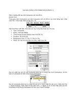
FIGURE 6.11
Examples of sketch text
The icons in the Sketch Text PropertyManager are fairly self-explanatory, other than the Rotated
Text option, which rotates individual letters, and not the whole string of text.
You can use the Sketch Text tool multiple times in a single sketch to make pieces of text with dif-
ferent properties. Each string of text has a placement point located at the lower left of the text. This
point can be given sketch relations or dimensions to locate the text.
Overlapping characters
194
Building Intelligence into Your Parts
Part II
12_080139 ch06.qxp 3/26/07 3:36 PM Page 194
If the text overlaps in places, as shown in Figure 6.10, you can correct this in a couple of ways.
First, you can extrude it with the Merge option turned off so that each letter is created as a separate
solid body. You can also explode sketch text so that it becomes simply lines and arcs in a sketch,
which you can edit the same as any other sketch.
Using Colors and Line Styles with Sketches
Custom colors and line styles are usually associated with drawings, not sketches; in fact, they are
most valuable when used for drawings. In sketches, this functionality is little known or used, but is
still of value in certain situations.
Color Display mode
In drawings, you can use the Color Display Mode button to switch sketch entities on the drawing
between displaying the assigned line or layer color and displaying the sketch status color. It has
exactly the same effect here in part and assembly sketches.
When you press the button, the sketch state colors are used. When the button is not pressed, any
custom colors that you have applied to the sketch entities will display. If the button is not pressed
and you have not applied colors to the entities, then the default sketch state colors are used.
You can use sketch colors for emphasis, to make selected sketch entities stand out, or to make
sketches with various functions immediately distinguishable. Color Display mode only has an
effect on an active sketch. Once a sketch is closed, it returns to the gray default color for inactive
sketch entities.
Line color
Line color enables you to assign color to entities in an active sketch. Whether the assigned color or
the default sketch status colors are used is determined by the Color Display Mode tool.
Edit color
You can use the Edit Color tool to assign color to an entire sketch. The color that you assign in this
way displays only when the sketch is inactive, instead of the default gray color. The colors that are
assigned to sketches in this way also follow the toggle state of the Color Display Mode button. For
example, if the Color Display Mode button is depressed, then inactive sketches display as gray.
When the Color Display Mode button is not pressed, then inactive sketches display in any color
that you have assigned by using the Edit Color tool.
Line thickness and line style
The Line Thickness and Line Style tools function independently from the Color Display Mode but-
ton, but they are still used only when the sketch is active. As soon as a sketch that contains entities
with edited thickness and style is closed, the display goes back to the normal line weight and font.
195
Getting More from Your Sketches
6
12_080139 ch06.qxp 3/26/07 3:36 PM Page 195
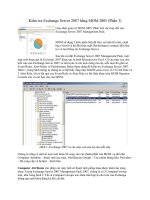
To assign a thickness or a style, you can select the sketch entities to be changed, press the button,
and select the thickness or style. Although a single sketch entity may have only a single thickness
or style, you can use multiple thicknesses or styles within a single sketch. Figure 6.12 shows a
sketch with the thickness and style edited.
FIGURE 6.12
A sketch with edited line thickness and line style
You can create custom line styles, but only in a drawing document; you cannot use custom line
styles in the part environment.
Line thickness and line styles are covered in more detail in the discussion of drawings in
Chapter 20.
Tutorial: Editing and Copying
This tutorial guides you through some common sketch relation editing scenarios and using some of
the Copy, Move, and Derive tools. Follow these steps to learn about editing and copying sketches:
1. Open the part named Chapter6 Tutorial1.sldprt from the CD-ROM. This part has several
error flags on sketches. In cases where there are many errors, it is best to roll the part
back and go through the errors one by one.
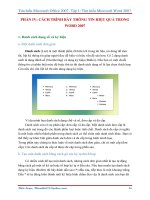
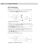
2. Drag the rollback bar from just after the last fillet feature to just after Extrude3. If
Extrude3 is expanded so that you can see Sketch3 under it, then drop the rollback bar to
after Sketch3. If a warning message appears, telling you that Sketch3 will be temporarily
unabsorbed, then select Cancel and try the rollback again. Figure 6.13 shows before and
after views for the rollback.
CROSS-REF
CROSS-REF
196
Building Intelligence into Your Parts
Part II
12_080139 ch06.qxp 3/26/07 3:36 PM Page 196
3. Edit Sketch3 and turn off the Sketch Relations display (View ➪ Sketch Relations). Click
Display/Delete Relations on the toolbar (the Eyeglasses tool), and set it to All in This
Sketch. Notice that all of the relations conflict, but only one is unsolvable: the Equal
Radius relation. This appears to be a mistake because the two arcs cannot be equal.
4. Delete the Equal Radius relation. The sketch is still not fixed.
5. Click the green check mark icon to close the Display/Delete Relations PropertyManager.
6. RMB click the graphics window and select SketchXpert. Click Diagnose.
FIGURE 6.13
Rolling the part back to Extrude3
7. Using the double arrows in the Results panel, toggle through the available solutions. All
of the solutions except one remove sketch relations. Accept the one solution that removes
the dimension, and click the green check mark icon to exit the SketchXpert. The sketch
no longer shows errors.
8. Close the sketch. Notice that the error flag does not disappear until the sketch has been
repaired and closed.
9. Use the rollback bar to roll forward to after Extrude2 and Sketch2. Figure 6.14 shows the
tooltip message that appears if you place the cursor over the feature with the error. With
time, you will begin to recognize the error messages by a single keyword or even by the
shape of the message text. This message tells you that there is a
dangling relation — a rela-
tion that has lost one of the entities.
Model in rolled back state
Rollback bar Rollback cursor
197
Getting More from Your Sketches
6
12_080139 ch06.qxp 3/26/07 3:36 PM Page 197
FIGURE 6.14
The Error tooltip
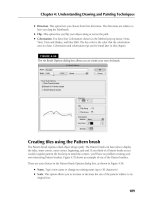
10. Edit the sketch. Figure 6.15 points out the dangling errors. If you show the Sketch
Relation icons again, the errors will be easier to identify. When you use Display/Delete
Relations, the first two Coincident relations appear to be dangling. Clicking the relation
in the Relations panel of the Display/Delete Relations PropertyManager shows that one
point was connected to a line and the other point was connected to a point.
11. When you have fixed the errors, exit the sketch and confirm that the flag is no longer on
Sketch2.
12. Drag the rollback bar to just before CutExtrude1. Edit 3DSketch1. This sketch is overde-
fined. If the Sketch Relations are not on at this point, then turn them on again.
Because this is a task that you will perform many times, this is a good opportunity
to set up a hotkey for this function. As a reminder, to set up a hotkey, go to Tools
➪
Customize ➪ Keyboard, and in the Search box, type
relations
. In the Shortcut column for this com-
mand, select a hotkey to use.
13. Double-click one of the relation icons; the Display/Delete Relations PropertyManager
appears. Notice that one of the sketch relations is a Fixed relation. Remove the Fixed rela-
tion, and exit the sketch.
14. RMB click anywhere in the FeatureManager and select Roll To End.
15. Click CutExtrude1 in the FeatureManager so that you can see it in the graphics window,
and then click a blank space to deselect the feature.
16. Ctrl-drag any face of the cut feature, and drop it onto another flat face. The Ctrl-drag
function copies the feature and the sketch, but the external dimensions and relations
become detached.
TIP
TIP
198
Building Intelligence into Your Parts
Part II
12_080139 ch06.qxp 3/26/07 3:36 PM Page 198
FIGURE 6.15
Fixing dangling errors
17. In the prompt that appears, click Dangle in response to the prompt. This means that you
will have to reattach some dangling dimensions rather than recreating them. Edit the
newly created sketch, which now has an error on it.
18. Two of the dimensions that went to external edges now have the olive dangling color.
Select one of the dimensions; a red handle displays. Drag the red handle and attach it to
a model edge. Do this for both dimensions. The dimensions update to reflect their new
locations. Exit the sketch and verify that the error flag has disappeared.
19. Expand CutExtrude1, and select Sketch5 under it. Ctrl-select a flat face on the model
other than the one that Sketch5 is on. In the menu, select Insert
➪ Derived Sketch. You
are put into a sketch editing the derived sketch.
20. The sketch is blue, and so you should be able to resize it, right? You can test this by drag-
ging the large circle; it only repositions the sketch as a unit.
Drag this point
to this corner
Two points with
dangling relations
Drag this point
to this edge
199
Getting More from Your Sketches
6
12_080139 ch06.qxp 3/26/07 3:36 PM Page 199
21. Dimension the center of the large circle to the edges of the model.
22. Drag the smaller circle, and notice that it swivels around the larger circle. Create an angle
dimension between the construction line between the circle centers and one of the model
edges. Notice that the sketch is now fully defined.
23. Exit the sketch, and look at the name of the derived sketch in the FeatureManager. The
term
derived appears after the name, and the sketch appears as fully defined.
24. RMB click the sketch and select Underive Sketch. Notice that the sketch is now underde-
fined. The Underive command removes the associative link between the two sketches.
Tutorial: Controlling Pictures,
Text, Colors, and Styles
This tutorial guides you through some of the miscellaneous functions in sketches, and shows you
what they are used for and how they are used. Follow these steps to learn how to control these items:
1. Open a new part using a template with inches as units. Open a sketch on the Front plane,
and draw a construction line 12 inches down (negative Y) from the Origin.
2. Insert a sketch picture in this sketch. Use Sketch Picture 1.tif from the CD-ROM for
Chapter 6.
3. Resize the image so that the endpoints of the construction line are near the centers of the
holes on the ends of the part. To move the image, just double-click it first, and then drag
it. To resize it, drag the corners.
4. In the Transparency panel of the Sketch Picture PropertyManager, select the Eyedropper
tool and click in the white background of the image. Make sure that the color field next
to the Eyedropper tool changes to white.
5. Slide the Transparency and Matching Tolerance sliders all the way to the right, or type
1.00 in the number boxes.
6. Close the sketch, and rename it Sketch Image Front View.
7. Put the image Sketch Picture 2.tif, also from the CD-ROM, on the Right plane, and resize
it to fit with the first image. Center it symmetrically about the Origin. Also set the trans-
parency to the same setting as the first image.
8. Open a new sketch, also on the Front plane, and draw two circles to match the features
on the ends. Extrude them using a Mid Plane extrusion to match the image in the other
direction (about 2.5 inches), as shown in Figure 6.16.
9. Open another new sketch on the Front plane and draw the tangent lines to form the web
in the middle of the part. Close the sketch to make a solid extrusion. Extrude this part .5
inches Mid Plane.
200
Building Intelligence into Your Parts
Part II
12_080139 ch06.qxp 3/26/07 3:36 PM Page 200
FIGURE 6.16
Using sketch pictures
10. Open a new sketch on the face of the large flat web that you created in the previous step,
and offset the arc edge of the larger circular boss by 2.1 inches.
11. Change the arc to a construction arc and drag its endpoints to approximately the position
shown in Figure 6.17. The endpoints of the arc are blue after you drag them. Give them a
Horizontal relation, and then dimension them as shown in Figure 6.17.
FIGURE 6.17
Creating an offset arc
12. Click Tools ➪ Sketch Entities ➪ Text to initiate the creation of sketch text.
13. Select the construction arc to go into the Curves window.
14. In the Text window, type SolidWorks. Select the Full Justify option.
201
Getting More from Your Sketches
6
12_080139 ch06.qxp 3/26/07 3:36 PM Page 201
15. Deselect the Use Document Font option, click the Font button, and then set the Units to
.50 inches. Click the Bold button to make the text thicker. Click OK to exit the dialog
box. Click the green check mark icon to exit the sketch text, and then exit the sketch.
16. Extrude the text to a depth of .050 inches with 3 degrees of draft. The part at this point
resembles Figure 6.18.
FIGURE 6.18
Creating extruded text
Sketch Text is a real performance killer. The more text that you use, the longer it takes to
extrude. Draft on the extrusion adds to the time required.
17. Select the flat face on the other side of the part from where you just extruded the text,
and open a sketch.
18. Select the face and click the Offset button to make a set of sketch entities offset to the
inside of the face by .50 inches.
19. Turn on the Line Format toolbar (RMB click any toolbar other than the
CommandManager and select Line Format).
20. Select all of the sketch lines, and change their color using the Line Color tool. Change the
line thickness and the line style using the appropriate tools. The sketch now looks some-
thing like Figure 6.19.
21. When you click the Color Display Mode tool, the colors return to regular sketch colors.
When you exit the sketch, the line weight and style also return to normal.
PERFORMANCE
PERFORMANCE
202
Building Intelligence into Your Parts
Part II
12_080139 ch06.qxp 3/26/07 3:36 PM Page 202
FIGURE 6.19
Using line thickness and line style
Summary
Many tools that are available in sketches are not commonly shown in the most popular sources of
information, including official training manuals. The difference between a good CAD tool and a
great communication tool can be some of these minor functions that just make life a little easier, or
the presentation or editing of data a little better. When you explore the capabilities of SolidWorks,
it usually rewards you with functionality that others might not find.
203
Getting More from Your Sketches
6
12_080139 ch06.qxp 3/26/07 3:36 PM Page 203
12_080139 ch06.qxp 3/26/07 3:36 PM Page 204
W
henever I do a woodworking project, the most frustrating part of
the job is to envision a result, but not be able to accomplish it
because I do not have the tools to get it done; worse yet is to
actually have the tools but either not understand how to use them or not
even realize that I have them. Getting the job done is so much more satisfy-
ing when you use the right tools and get the job done right — not just so
that it
looks right, but so that it really is right.
I see users run into the same issues with SolidWorks. SolidWorks offers so
many “tools in the toolbox” that it is sometimes difficult to select the best
one, especially if it is for a function that you do not use frequently.
This chapter helps you to understand how each feature functions, and offers
situations when they are best applied or avoided.
Identifying When to
Use Which Tool
I am always trying to think of alternate ways of doing things. Especially
when working with complex features, it is important to have a backup plan,
or sometimes multiple backup plans. Even when the part is not that compli-
cated, every situation is different. You probably will not get away with just
doing blind extrudes and cuts with simple chamfers and fillets for the rest of
your career. And even if you could, who would want to?
205
IN THIS CHAPTER
Identifying when to
use which tool
Creating curve features
Filleting
Selecting a specialty feature
Tutorial: Bracket casting
Tutorial: Creating a
wire-formed part
Choosing a Feature Type
13_080139 ch07.qxp 3/26/07 3:37 PM Page 205
As an exercise, I often try to see how many different ways a particular shape might be modeled,
and how each modeling method relates to manufacturing methods, costs, editability, efficiency,
and so on. You may also want to try this approach.
Extrude
Extruded features can be grouped into several categories, with extruded Boss and Cut features
at the highest level. Boss and Cut are two separate feature types and cannot be interchanged.
Sketches may be shared between features or reused after a feature has been deleted.
The “Base” part of the Extruded Boss/Base is a holdover from when SolidWorks did not allow
multibody parts, and the first feature in a part had special significance that it no longer has. This
is also seen in the menus at Insert
➪ Boss/Base. The Base feature was the first solid feature in the
FeatureManager, and you could not change it without deleting the rest of the features. The intro-
duction of multibody support in SolidWorks has removed this limitation.
Multibody parts are covered in detail in Chapter 26.
Solid Feature
In this case, we use the term solid feature as opposed to thin feature. This is the simple type of fea-
ture that you create by default when you extrude a closed loop sketch. A closed loop sketch fully
encloses an area without gaps or overlaps at the sketch entity endpoints. Figure 7.1 shows a closed
loop sketch creating an extruded solid feature.
Thin Feature
The Thin Feature option is available to several types of features, but is most commonly used with
Extruded Boss features. Thin features are created by default when you use an open loop sketch,
but you can also select this option for closed loop sketches. Thin features are commonly used for
ribs, thin walls, hollow circular bosses, and many other types of features that are common to plas-
tic parts or castings.
Even experienced users tend to forget that thin features are not just for bosses, but can also be used
for cuts. For example, you can easily create grooves and slots with thin feature cuts.
Figure 7.2 shows the Thin Feature panel in the Extruded Boss PropertyManager. In addition to
the default options that are available for the Extrude feature, the Thin feature adds a
thickness
dimension, as well as three options to direct the thickness relative to the sketch: One-Direction,
Mid-Plane, and Two-Direction. The Two-Direction option requires two dimensions, as shown in
Figure 7.2.
CROSS-REF
CROSS-REF
206
Building Intelligence into Your Parts
Part II
13_080139 ch07.qxp 3/26/07 3:37 PM Page 206
FIGURE 7.1
A closed loop sketch and an extruded solid feature
FIGURE 7.2
The Thin Feature interface
Thin feature sketches are simpler, which always means that they are more robust through changes.
You can create the simplest cube from a single sketch line and a thin feature extrude. However,
in some respects, they are not as flexible when the design intent changes. For example, if a part is
going to change from a constant width to a tapered or stepped shape, thin features do not handle
this kind of change well. Figure 7.3 shows different types of geometry that are created from thin
features.
207
Choosing a Feature Type
7
13_080139 ch07.qxp 3/26/07 3:37 PM Page 207
FIGURE 7.3
Different types of geometry created from thin features
Sketch types
I have already mentioned several sketch types, including closed loop and open loop. Closed loop
sketches make solid features by default, but you can also use them to make thin features. Open
loop sketches make thin features by default, and you cannot use them to make solid features.
Sketch contours
Sketch Contour is a feature that is used in other competing CAD packages and that SolidWorks has
adopted, probably more to match features in the competing software than to create a better way of
doing things. Using sketch contours seems to promote sloppy work, although in some cases, they
act as valid time savers.
In general, sketch contours enable you to select enclosed areas where the sketch entities themselves
actually cross or otherwise violate the usual sketch rules. One of these conditions is the self-
intersecting contour.
208
Building Intelligence into Your Parts
Part II
13_080139 ch07.qxp 3/26/07 3:37 PM Page 208
SolidWorks works best with well-disciplined sketches that follow the rules. As a result, if
you plan to use sketch contours, then you should make sure that it is not simply because
you are unwilling to clean up a messy sketch.
When you define features by selecting sketch contours, they are more likely to fail if the selection
changes when the selected contour’s bounded area changes in some way. It is best practice to use the
normal closed loop sketch when you are defining features. Contour selection is best suited to “fast
and dirty” conceptual models, which are used in very limited situations for production models.
As shown in Figure 7.4, there are several types of contour selection.
3D sketch
You can make extrusions from 3D sketches, even 3D sketches that are not planar. While not
necessarily the best way to do extrudes, this is a method that you can use when needed. You can
establish direction for an extrusion by selecting a plane (normal direction), axis, sketch line, or
model edge.
FIGURE 7.4
Types of contour selection
Selecting an enclosed area from
a single self-intersecting profile
Selecting multiple areas
as contours in a sketch
Selecting the border as a contour
BEST PRACTICE
BEST PRACTICE
209
Choosing a Feature Type
7
13_080139 ch07.qxp 3/26/07 3:37 PM Page 209
When you make an extrusion from a 3D sketch, the direction of extrusion cannot be assumed or
inferred from anything — it must be explicitly identified. Extrusion direction from a 2D sketch is
always perpendicular to the sketch plane unless otherwise specified.
Non-planar sketches become somewhat problematic when you are creating the final extruded fea-
ture. The biggest problem is how you cap the ends. Figure 7.5 shows a non-planar 3D sketch that
is being extruded. Notice that the end faces are, by necessity, not planar, and are capped by an
unpredictable method. This is a problem only if your part is going to use these faces in the end; if
it does not, then there may be no issue with using this technique. If you would like to examine this
part, it is included on the CD-ROM as Chapter 7 Extrude 3D Sketch.sldprt.
FIGURE 7.5
Extruding a non-planar 3D sketch
If you need to have ends with a specific shape, and you still want to extrude from a non-planar 3D
sketch, then you should use an extruded surface feature rather than an extruded solid feature.
Surfacing features are covered in detail in Chapter 27. Chapter 5 contains additional
details on extrude end conditions, thin features, directions, and the From options.
Revolve
Like all other features, revolve features have some rules that you must observe when choosing
sketches that can be used to create a revolve:
n
Draw only half of the revolve profile (draw the section to one side of the centerline).
n
The profile must not cross the centerline.
CROSS-REF
CROSS-REF
210
Building Intelligence into Your Parts
Part II
13_080139 ch07.qxp 3/26/07 3:37 PM Page 210
n
The profile must not touch the centerline at a single point. It can touch along a line, but
not at a point. Revolving a sketch that touched the centerline at a single point would cre-
ate a point of zero thickness in the part.
You can use any type of line or model edge for the centerline, not just the centerline/construction
line type.
End conditions
There are three Revolve end conditions:
n
One-Direction: The revolve angle is driven in a single direction.
n
Two-Direction: The revolve angle can be driven in two independent directions.
n
Mid-Plane: The revolve angle is divided equally in opposite directions.
There is no equivalent for Up to Vertex, Up to Next, Up to Surface, or Up to Body with the Revolve
feature.
Contour selection
Like extrude features, revolve features can also use contour selection; as with the extrude features, I
recommend that you avoid using contours.
Loft
Many users struggle when faced with the option to create a loft or a sweep. Some overlap exists
between the two features, but as you gain some experience, it becomes easier to choose between
them. Generally, if you can create the cross-section of the feature by manipulating a single sketch,
then a sweep might be the best feature. If the cross-section changes character or severely changes
shape, then a loft may be best. If you need a very definite shape at both ends and/or in the
middle, then a loft is a better choice because it allows you to explicitly define the cross-section
at a point. However, if the outline is more important than the cross-section, then you should
choose a sweep. If the path between ends is important, choose a sweep. If the ends themselves
are more important and you just want to blend from one end to the other, then the loft is the
better choice.
Both types of features are extremely powerful, but the sweep has a tendency to be fussier about
details, setup, and rules, while the loft can be surprisingly flexible. I am not trying to dissuade
you from using sweeps, because they are useful in many situations. However, in my own personal
modeling, I probably use about ten lofts for every sweep. For example, while you would use a loft
or combination of loft features to create a complex laundry detergent bottle, you would use the
sweep to create a raised border around the label area.
Lofts are an example of
interpolated geometry. That is to say that the loft is outlined by creating
several loft sections and guide curves, and then the software interpolates the face geometry in
between the sections. A good example of this is to put a circle on one plane and a rectangle on an
211
Choosing a Feature Type
7
13_080139 ch07.qxp 3/26/07 3:37 PM Page 211
offset plane and then loft them together. This arrangement is shown in Figure 7.6. The transition
between shapes is the defining characteristic of a loft, and is also the reason for choosing a loft
instead of another feature type. Lofts can create both Boss features and Cut features.
FIGURE 7.6
A simple loft
The two-profile loft with default end conditions always creates a straight transition, which is
shown in the image to the left. A two-point spline with no end tangency creates a straight line in
exactly the same way. By applying end conditions to either or both of the loft profiles, the loft’s
shape is made more interesting, as seen in the image to the right in Figure 7.6. Again, the same
thing happens when applying end tangency conditions to a two-point spline: it goes from being a
straight line to being more curvaceous, with continuously variable curvature. The Loft
PropertyManager interface is shown in Figure 7.7.
Entities that you can use in a loft
For solid lofts, you can select faces, closed loop 2D or 3D sketches, and surface bodies. You can
use sketch points as a profile on the end of a loft that comes to a point or rounded end. For surface
lofts, you can use open sketches and edges in addition to the entities that are used by solid lofts.
Some special functionality becomes available to you if you put all of the profiles and guide curves
together in a single 3D sketch. In order to select profiles made in this way, you must use the
SelectionManager, which is discussed later in this chapter.
The Sketch Tools panel of the Loft PropertyManager enables you to drag sketch entities of any pro-
file made in this way while you are editing or creating the Loft feature, without needing to exit and
edit a sketch.
212
Building Intelligence into Your Parts
Part II
13_080139 ch07.qxp 3/26/07 3:37 PM Page 212
FIGURE 7.7
The Loft PropertyManager
While this sort of functionality may be attractive for a lot of reasons, you should not
choose this way. Unless you are dealing with the simplest of geometry and sketch rela-
tions, 3D sketches — and more specifically 3D sketch planes — are simply not up to the task. It is def-
initely true that 3D sketches in SolidWorks work far better than they used to, but I would still not put
even a 3D sketch of medium complexity in a part that I had to depend on for production data. The
specific problem is sketch relations. I discuss 3D sketches in more detail in Chapter 31.
The similarities between lofts and splines
The words “loft” and “spline” come to us from the shipbuilding trade. The word “spline” is actually
defined as the slats of wood that cover the ship, and the spars of the hull very much resemble loft
sections. With the splines or slats bending at each spar, it is easy to see how the modern CAD anal-
ogy came to be.
CAUTION
CAUTION
213
Choosing a Feature Type
7
13_080139 ch07.qxp 3/26/07 3:37 PM Page 213
Lofts and splines are also governed by similar mathematics. You have seen how the two-point
spline and two-profile loft both create a straight-line transition. Next, a third profile is added to the
loft and a third point to the spline, which demonstrates how the math that governs splines and
lofts is also related to bending in elastic materials. Figure 7.8 shows how lofts and splines react
geometrically in the same way that bending a flexible steel rod would react (except that the spline
and the loft do not have a fixed length).
FIGURE 7.8
Splines, lofts, and bending
With this bit of background, it is time to move forward and talk about a few of the major aspects
of Loft features in SolidWorks. It is probably possible to write a separate book that only discusses
modeling lofts and other complex shapes. In this single chapter, I do not have the space to cover
the topic exhaustively, but coverage of the major concepts will be enough to point you in the right
direction.
The need for surfaces
In this chapter, I deal exclusively with solid modeling techniques because they are the baseline that
SolidWorks users use most frequently. Surfaces make it easier to discuss complex shape concepts
because surfaces are generally created one face at a time, rather than by using the method with
solid modeling that creates as many faces as necessary to enclose a volume.
From the very beginning, the SolidWorks modeling culture has made things easier for users by
taking care of many of the details in the background. This is because solids are built through auto-
mated surface techniques. Surface modeling in itself can be tedious work because of all of the
Three-point spline, no end conditions
End tangency changed
Reacts like a pinned joint
Notice slight bulge,
just like a real rod in bending
214
Building Intelligence into Your Parts
Part II
13_080139 ch07.qxp 3/26/07 3:37 PM Page 214
manual detail that you must add. Solid modeling as we know it is simply an evolutionary step that
adds automation to surface modeling. The automation maintains a closed solid boundary around
the volume.
Because surfaces are the underlying building blocks from which solids are made, it would make
sense to teach surfaces first, and then solids. However, the majority of SolidWorks users never use
surfacing, and do not see a need for it, and so surface functions are generally given a lower priority.
You can refer to Chapter 27 for surfacing information.
Loft end constraints
Loft end conditions control the tangency direction and weighting at the ends of the loft. Some of
the end constraints depend upon the loft starting or ending from other geometry. The optional
constraints include the following:
None
The direction of the loft is not set by the None end constraint, but the curvature of the lofted faces
at the ends is zero. This is the default end constraint for two-section lofts.
Default
The Default end constraint is not available for two-section lofts, only for lofts with three or more
sections. This end constraint applies curvature to the end of the loft so that it approximates a
parabola being formed through the first and last loft profiles.
The SolidWorks help file makes a special point to explain the difference between the None and
Default end constraints, but the Default help makes it look as if it works with only two profiles,
when in fact it does not.
Tangent to Face
The Tangent to Face end constraint is self-explanatory. This end constraint may fail or cause
unwanted ripples or puckers in the part if profiles that are adjacent to one another or touch at an
edge are lofted together. The Tangency to Face option includes a setting for tangent length. This is
not a literal length dimension, but a relative weighting, on a scale from 0.1 to 10. The small arrow
to the left of the setting identifies the direction of the tangency. Usually, the default setting is cor-
rect, but there are times when SolidWorks misidentifies the intended tangency direction, and you
may need to correct it manually.
The Next Face option is available only when lofting from an end face where the tangency could go
in one of two perpendicular directions. This is shown in Figure 7.9.
Apply to All refers to applying the Tangent Length value to all of the tangency-weighting arrows for
the selected profile. When you select Apply to All, only one arrow displays. When you deselect it,
one arrow should display for each vertex in the profile, and you can adjust each arrow individually.
CROSS-REF
CROSS-REF
215
Choosing a Feature Type
7
13_080139 ch07.qxp 3/26/07 3:37 PM Page 215
FIGURE 7.9
Examples of end constraints
Curvature to Face
The difference between tangency and curvature is that tangency is only concerned with the direc-
tion of curvature immediately at the edge between the two surfaces. Curvature must be tangent
and in addition match the radius of curvature on either side of the edge between surfaces. This
is often given many names, including curvature continuity, c2, and others. Lofted surfaces do
not usually have a constant radius; because they are like splines, they are constantly changing in
local radius.
None
Default
Both ends set to
Normal to Profile
Tangent to Face
Tangent to Face
Tangency to Face
with Other Face option
Direction vector
216
Building Intelligence into Your Parts
Part II
13_080139 ch07.qxp 3/26/07 3:37 PM Page 216
Direction Vector
The Direction Vector end constraint forces the loft to be tangent to a direction that you define by
selecting an axis, edge, or sketch entity. The angle setting makes the loft deviate from the direction
vector, as shown in Figure 7.9. The curved arrows to the left identify the direction in which the
angle deviation is going.
Isoparameter U-V lines
The mesh or grid shown in the previous images appears automatically for certain types of features,
including lofts. The grid represents
isoparameter lines, also known as NURBS mesh or U-V lines.
This mesh shows the underlying structure of the faces being created by the feature. If the mesh is
highly distorted and appears to overlap in places, then it is likely that the feature will fail.
You can show or hide the mesh through the RMB menu when editing or creating a Loft feature,
unless the SelectionManager is active. In this case, you can see only SelectionManager commands
in the RMB menu. In addition, planar faces do not mesh, only faces with some curvature.
Guide curves
Guide curves help to constrain the outline of a loft between loft profiles. Although it is best to try
to achieve the shape you want by using appropriately shaped and placed loft profiles, I recognize
that this is not always possible. The most appropriate use of guide curves for solid lofts is at places
where the loft is going to create a hard edge, which is usually at the corners of loft profile sketches.
Guide curves often (but not always) break up what would otherwise be a smooth surface, and you
should avoid them in these situations, if possible.
Do not try to push the shape of the loft too extremely with guide curves. Guide curves
should be used mainly for tweaking and fine-tuning rather than coarse adjustment. Use
loft sections and end constraints to get most of the overall shape correct. Pushing too hard with a
guide curve can cause the shape to kink unnaturally.
Although guide curves may be longer than the loft, they may not be shorter. The guide curve
applies to the entire loft. If you need to apply the guide curve only to a portion of the loft, then
split the loft into two lofts, one that uses the guide curve, and the other that does not. The guide
curve must intersect all profiles in a loft.
If you have more than one guide curve, the order in which they are listed in the box is important.
The first guide curve helps to position the intermediate profiles of the loft. It may be difficult or
impossible to visualize the effects of guide-curve order before it happens, but remember that it
does make a difference, and depending on the difference between the curves, the difference may or
may not be subtle.
Guide curves are also used in sweeps, which are dealt with later in this chapter. Figure 7.10 shows
a model that is lofted using guide curves. The image to the left shows the sketches that are used to
make the part. There are two sketches with points; you can use points as loft profiles. The image in
BEST PRACTICE
BEST PRACTICE
217
Choosing a Feature Type
7
13_080139 ch07.qxp 3/26/07 3:37 PM Page 217