Modelling with AutoCAD 2004 phần 3 pdf
Bạn đang xem bản rút gọn của tài liệu. Xem và tải ngay bản đầy đủ của tài liệu tại đây (1.06 MB, 35 trang )
20 The screen display should resemble Fig. 9.2(c)
21 Save the screen configuration as CONF4
22 Task
Restore the screen to a single viewport configuration to display the original model layout
23 At the command line enter -VPORTS ϽRϾ and:
prompt Enter an option [Save/Restore
enter R ϽRϾ – the restore option
prompt Enter name of viewport configuration to restore
enter CONF1 ϽRϾ
and screen displays the first saved configuration
24 Restore the other three saved viewport configurations using the command line–VPORTS,
then restore the display to a single viewport
25 Notes:
a) The command line entry -VPORTS gives the user the viewport options at the
command line. This was deliberate for this first example.
b) Generally the viewports command is activated from the menu bar in dialogue box form
26 Menu bar with View-Viewports-Named Viewports and:
prompt Viewports dialogue box
with Named Viewports tab active
and four saved viewport configurations
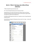
respond pick CONF3 then OK – Fig. 9.3
27 The screen will display the named viewport configuration
28 Using the Named viewport dialogue box, display the other named viewports then
restore the model in the original single viewport as opened
29 This completes the first viewport exercise. If you want to save the exercise (with the
viewport configurations) DO NOT USE THE NAME 3DWFM
60 Modelling with AutoCAD 2004
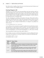
Figure 9.3 The Viewports dialogue box with the Named Viewports tab active.
Example 2
The first exercise used an already created 3D model to investigate the viewport com-
mand and configurations. This current exercise will create a new 3D wire-frame model
interactively using a four viewport configuration with preset 3D viewpoints. This will
allow the user to ‘see’ the model being created in all four viewports at the one time.
1 Open your 3DSTDA3 template file to display the black border at a 3D viewpoint with
layer MODEL current
2 Menu bar with View-Display-UCS Icon and check both On and Origin are active
(tick) – they should be!
3 Menu bar with Tools-New UCS-Origin and:
prompt Specify new origin point
enter 50,50,0 ϽRϾ
and icon moves to the entered point and is displayed as a UCS icon
4 Save this UCS position as BASE
5 Menu bar with View-Viewports-New Viewports and:
prompt Viewports dialogue box with New Viewports tab active
respond 1. New name: enter SCREEN DISPLAY 1
2. Standard viewports: pick Four: Equal
3. Apply to: Display
4. Setup: scroll and pick 3D
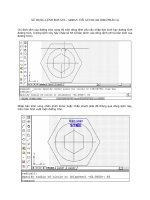
5. Change view to: do not alter (Fig. 9.4)
6. pick OK
Tiled viewports 61
Figure 9.4 The Viewports dialogue box with the New Viewports tab active.
6 The screen will display a four viewport configuration with the black border displayed
in each. Note the ‘appearance’ of the icon in the top two, and lower right viewports –
it has the same configuration in each, despite the different viewpoints set in the New
Viewports dialogue box (respond 4 in step 5).
7 Making each viewport active in turn, enter the following at the command line
UCSVP ϽRϾ and:
prompt Enter new value for UCSVPϽ1Ͼ
enter 0 ϽRϾ
8 Making each viewport active in turn, at the command line enter ZOOM ϽRϾ then
0.9 ϽRϾ
9 The screen layout at this stage is similar to Fig. 9.5(a)
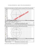
10 With the lower left viewport active, construct the model base using the LINE icon with:
Start point 0,0,0 ϽRϾ pt1
Next point @200,0,0 ϽRϾ pt2
Next point @0,120,0 ϽRϾ pt3
Next point @200Ͻ180,0 ϽRϾ pt4
Next point close – Fig. 9.5(b) in 3D
11 Using the LINE command construct the front vertical side with:
Start point Endpoint of pt1
Next point @20,0,100 ϽRϾ pt5
Next point @120,0,0 ϽRϾ pt6
Next point Endpoint of pt2
Next point right-click/enter – Fig. 9.5(c) in 3D
62 Modelling with AutoCAD 2004
Figure 9.5 Construction of model for viewport Example 2.
12 The top surface is created with the LINE command and:
Start point Endpoint of pt6
Next point @0,80,0 ϽRϾ pt7
Next point @Ϫ120,0,0 ϽRϾ pt8
Next point Endpoint of pt5
Next point right-click/enter – Fig. 9.5(d) in 3D
13 Add the sloped sides with lines joining points 3–7 and 4–8 as Fig. 9.5(e) in 3D
14 Make layer OBJECTS (blue) current and draw a circle with centre: 80,40,100 and radius:
25 – Fig. 9.5(f) in 3D
15 Menu bar with Draw-Surfaces-3D Surfaces and:
prompt 3D Objects dialogue box
respond pick Box3d then OK
prompt Specify corner of box and enter: 80,30,0
prompt Specify length of box and enter: 50
prompt Specify width of box and enter: 40
prompt Specify height of box and enter: 30
prompt Specify rotation angle of box about Z axis and enter: 20
16 a) Make layer TEXT current
b) Rotate UCS about X axis by 90 and save as FRONT
c) Menu bar with Draw-Text-Single Line Text and add the text item AutoCAD,
centred on 80,50 with height 20 and rotation 0
17 a) Set a 3 point UCS on the right sloped surface with:
1. origin: midpoint of line 23 – Fig. 9.5(e)
2. x axis: intersection of pt3
3. y axis: perpendicular to line 67
4. save UCS as SLOPE
b) Add the single line text item R2004, centred on Ϫ5,50 with a height of 15 and a
rotation angle of 0
18 The complete four viewport configuration display should be similar to Fig. 9.6
19 Save the drawing as MODR2004\TEST3D
20 This completes the two exercises on viewports
21 Notes:
1. A new system variable was used during this exercise, this being UCSVP. This vari-
able determines whether the UCS in an active viewport will ‘reflect’ the UCS orien-
tation of that active viewport and:
a) UCSVP 0: unlocked, i.e. the UCS will reflect the UCS of the current active viewport
b) UCSVP 1: locked, i.e. UCS is independent of the UCS in the current active viewport
2. The default UCSVP value is 1, i.e. locked
3. It is my personal recommendation that the UCSVP is set to 0, i.e. it should
always reflect the UCS position in any active viewport
4. The UCSVP must be set in every created viewport.
Tiled viewports 63
Summary
1 Viewports allow multi-screen configurations to be set
2 There are two types of viewport – TILED and UNTILED
3 The viewport type is controlled by the system variable TILEMODE and:
a) TILEMODE 1: tiled viewports (fixed)
b) TILEMODE 0: untiled viewports (movable) – more later
4 Tiled viewports can have between 1 and 4 ‘divisions’ and ‘fill the screen drawing area’
5 Multi-screen viewports are generally used with the viewpoint command and their full
benefit will not be appreciated until the various viewpoint options are discussed
6 Multiple viewport layouts are essential to 3D modelling.
64 Modelling with AutoCAD 2004
Figure 9.6 Completed viewport example 2 – TEST3D.
3D Views (or viewpoints) determine how the user ‘looks’ at a model and has been
used in previous chapters without any discussion about how it is used. In this chapter
we will investigate the command in detail using previously created models. When
combined with viewports, the user has a very powerful draughting aid – multiple
viewports displaying different views of a model.
The viewpoint command has the following selection options:
a) Isometric views: SW, SE, NE, NW
b) Orthographic views: Top, Bottom, Left, Right, Front, Back
c) Plan view: to current UCS, WCS, named UCS
d) Viewpoint: with rotate, compass and tripod, vector options
e) Viewpoint Presets: dialogue box selection
f) Real-time rotation with 3D Orbit
g) New Viewports dialogue box
In this chapter we will investigate all of the above selections.
The Viewpoint ROTATE option
This option requires two angles to be entered by the user:
a) the angle in XY plane from the X axis – the view direction
b) the angle from XY plane – the inclination (tilt)
1 Open your MODR2004\3DWFM drawing and:
a) erase any dimensions and hatching
b) leave all text items – they will act as a ‘reference’ as the model is viewed from
different angles
2 Layer MODEL current, UCS BASE and SE Isometric viewpoint
3 Refer to Fig. 10.1A
4 At the command line enter VPOINT ϽRϾ and:
prompt ***Switching to WCS***
and Current view direction: VIEWDIR=1.00,Ϫ1.00,1.00
then Specify a view point or [Rotate]Ͻdisplay compass and
tripodϾ
enter R ϽRϾ – the rotate option
prompt Enter angle in XY plane from X axis
enter 40 ϽRϾ
prompt Enter angle from XY plane
enter 0 ϽRϾ
prompt ***Returning to UCS***
then Regenerating drawing
and model displayed as Fig. 10.1(a1), i.e. looking towards the right-rear side
from a horizontal ‘stand-point’ – the view direction
Chapter 10
3D Views (Viewpoints)
5 At the command line enter VPOINT ϽRϾ and:
prompt Specify a view point or [Rotate]
enter R ϽRϾ – the rotate option
prompt Enter angle in XY plane from X axis and enter: 90 ϽRϾ
prompt Enter angle from XY plane and enter: 0 ϽRϾ
and model displayed as Fig. 10.1(a2)
6 Repeat the VPOINT command from the command line with the rotate option and
enter the following angle values at the prompts:
prompt 1 prompt 2 fig
215 0 a3
330 0 a4
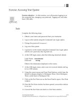
7 Restore the original SE Isometric viewpoint and refer to Fig. 10.1B
8 Use the VPOINT command with the rotate option, and enter the following angles at
the prompts:
prompt 1 prompt 2 fig
045b1
0 135 b2
0 270 (Ϫ90) b3
0 Ϫ45 (315) b4
66 Modelling with AutoCAD 2004
Figure 10.1 3D Views – the VPOINT Rotate option with 3DWFM.
9 Restore the SE Isometric viewpoint and refer to Fig. 10.1C. Activate the VPOINT
Rotate command and enter the following angles:
prompt 1 prompt 2 fig
40 70 c1
40 Ϫ30 c2
Ϫ20 20 c3
10 Restore the original SE Isometric viewpoint
11 Task
Make some other saved UCS settings current, e.g. SLOPE1, VERT1, etc and repeat the
Viewpoint Rotate command using some of the above angle entries. The model display
should be unaffected by the UCS position. Think about the prompt ***Switching to
the WCS***
12 Explanation of option
a) Prompt 1: angle in XY plane from the X axis
This is the viewer’s stand-point on the XY horizontal plane looking towards the
model, i.e. it is your view direction. If this angle is 0 degrees you are looking at the
model from the right side. If the angle is 270 degrees you are looking onto the front
of the model. The value of this angle can be between 0 and 360 degrees. It can also
be positive or negative and remember that 270 degrees is the same as Ϫ90 degrees.
b) Prompt 2: angle from the XY plane
This is the viewer’s ‘head inclination’ looking at the model, i.e. it is the angle of
tilt. A 0 degrees value means that you are looking at the model horizontally and a
90 degrees value is looking vertically down. The angle of tilt can vary between
0 and 360 degrees and be positive or negative with:
positive tilt: looking down on the model
negative tilt: looking up at the model.
13 Note:
The reader must realise that the displays in Fig. 10.1 have been ‘scaled’ to fit the one
sheet, and that your model displays will be larger than those illustrated.
VPOINT ROTATE using the presets dialogue box
1 3DWFM displayed at SE Isometric setting with UCS BASE?
2 Menu bar with View-3D Views-Viewpoint Presets and:
prompt Viewpoint Presets dialogue box – Fig. 10.2
with 1. viewing angle: absolute to WCS
2. angle from X axis: 315 – left-hand ‘clock’
3. angle from XY plane: 35.3 – right-hand ‘arc’
3 This dialogue box allows:
a) viewing angle to be absolute to WCS or relative to UCS
b) angles to be set by selecting clock/arc position
c) angles to be set by altering values at From: line
d) plan views to be set
4 Respond to the dialogue box with:
a) leave absolute to WCS
b) change the X axis angle from 315 to 150
c) change the XY plane angle from 35.3 to 10
d) pick OK
e) the model will be displayed at the entered viewpoint angles
3D Views (Viewpoints) 67
5 Make UCS SLOPE1 current
6 Menu bar with View-3D Views-Viewpoint Presets and:
a) make Relative to UCS active – black dot
b) leave the two angle values as 150 and 10
c) pick OK
d) the model is displayed at the entered viewpoint angles but differs from the step 4
display due to the UCS setting
7 Task
a) Try some other entries from the Viewpoint Presets dialogue box using both selec-
tion methods, i.e. the clock/arc and altering the angles
b) Investigate the difference in the display with the Absolute to WCS and Relative to
UCS selections
c) Restore UCS BASE and the SE Isometric viewpoint
8 This completes the Viewpoint Rotate exercise. Do not save any changes to the 3DWFM
model.
The Viewpoint COMPASS and TRIPOD option
This option allows the user to set ‘infinite viewpoints’. Older users of AutoCAD will
remember this as the bulls-eye and target method. We will demonstrate the command
with a different model so:
1 Open the MODR2004\TEST3D model created during the viewport exercise and refer
to Fig. 10.3
2 Ensure UCS BASE is current and make the lower left viewport active, i.e. the 3D
Viewport
3 Menu bar with View-Viewports-1 Viewport to display a single viewport of the
model at a 3D Viewpoint. This model ‘fills the screen’.
68 Modelling with AutoCAD 2004
Figure 10.2 The Viewpoint Presets dialogue box.
4 Menu bar with View-3D Views-Viewpoint and:
prompt 1. model ‘disappears’
2. screen displays the XYZ tripod and the compass
3. cursor replaced by a small cross (ϩ)
4. axes and cross (ϩ) move as mouse is moved
respond move the cross (ϩ) into the circle quadrant indicated in Fig. 10.3(a) and
left-click
and model displayed at this viewpoint, and is viewed from above
5 At the command line enter VPOINT ϽRϾ and:
prompt ***Switching to WCS***
then Specify a viewpoint or [Rotate]Ͻdisplay compass and
tripodϾ
respond press ϽRETURNϾ
prompt tripod and compass displayed
respond move the cross (ϩ) into the circle quadrant indicated in Fig. 10.3(b) and
left-click
and model displayed at this new viewpoint
6 Repeat the tripod viewpoint option (menu bar or command line) and position the
cross (ϩ) in the quadrants indicated in Fig. 10.3
i.e. (c)–(d): within the inner circle
(e)–(h): between the inner and outer circles
3D Views (Viewpoints) 69
Figure 10.3 3D Views – the Viewpoint COMPASS and tripod option with TEST3D.
7 Task
When you are capable of using the compass and tripod, try the following:
a) position the ϩ at different points on the two axes and observe the resultant displays
b) position the ϩ at different points on the circle circumferences and note the displays
8 Explanation of option
a) The ‘bulls-eye’ is in reality a representation of a glass globe and the model is located
at the centre of the globe. The XY plane is positioned at the equator. The north pole
of the globe is at the circle centres and the two concentric circles represent the
surface of the world, stretched out onto a flat plane with:
1. the circle centre: the north pole
2. the inner circle: the equator
3. the outer circle: the south pole
b) As the cross (ϩ) is moved about the circles, the user is moving around the surfaces
of the globe and:
Cross (ϩ) position View result
1. in inner circle above equator, looking down on model
2. in outer circle below equator, looking up at model
3. on inner circle looking horizontally at model
4. below horizontal viewing from the front
5. above horizontal viewing from the rear
9 This completes the tripod option exercise. Do not save changes.
The Viewpoint VECTOR option
1 Open MODR2004\3DWFM with UCS BASE and SE Isometric viewpoint
2 Erase any dimensions and hatching, but leave the text items as they will act as a ‘ref-
erence’ as the model viewpoint is altered
3 Refer to Fig. 10.4
4 Menu bar with View-3D Views-Viewpoint and:
prompt ***Switching to WCS***
then Current view direction
and Specify a view point or [Rotate]
enter 0,0,1 ϽRϾ
prompt ***Returning to the UCS***
and 1. the model will be displayed at the entered viewpoint
2. it is a top view – Fig. 10.4(a)
3. it ‘fills the screen’
6 At the command line enter VPOINT ϽRϾ and:
prompt Specify a view point or [Rotate]
enter 0,؊1,0 ϽRϾ
and model displayed as Fig. 10.4(b) – a front view
7 Repeat the viewpoint vector option (menu bar or command line) and enter the following
co-ordinates at the prompt line:
Vector entry resultant view fig (Fig. 10.4)
1,0,0 from right c
0,1,0 from rear d
Ϫ1,0,0 from left e
0,0,Ϫ1 from below f
1,1,1 3D from above g
Ϫ1,Ϫ1,Ϫ1 3D from below h
8 Restore the original SE Isometric viewpoint
70 Modelling with AutoCAD 2004
9 Task
Try some vector entries for yourself then restore the original SE Isometric viewpoint
10 Explanation of option
a) The vector option allows the user to enter x,y,z co-ordinates. These are the co-ordinates
of the viewers’ ‘stand-point’ looking at the model which is considered to be at the
origin. Thus if you enter 0,0,1 you are ‘standing’ at the point 0,0,1 looking towards
the origin. As this point is on the positive Z axis you are looking down on the
model, i.e. a top view.
b) The actual numerical value of the vector entered does not matter, i.e. 0,0,1; 0,0,12;
0,0,99.99; 0,0,3456 are all the same viewpoint entries. I prefer to use the number 1,
hence 0,0,1; Ϫ1,0,0 etc.
c) Certain vector entries give the same display as rotate option and the following lists
some of these similarities:
vector rotate view
0,0,1 0,90 top
0,Ϫ1,0 270,0 front
1,0,0 0,0 right
0,1,0 90,0 rear
Ϫ1,0,0 180,0 left
0,0,Ϫ10,Ϫ90 bottom
1,1,1 45,35 3D from above
Ϫ1,Ϫ1,Ϫ1 Ϫ135,Ϫ35 3D from below
11 This completes the vector option. Do not save any changes.
3D Views (Viewpoints) 71
Figure 10.4 3D Views – the Viewpoint VECTOR option with 3DWFM.
The isometric viewpoints
The isometric 3D Views allow the user to view a model from four ‘preset’ viewpoints,
these being SW, SE, NE and NW. These four viewpoints are used extensively as they
allow easy access to viewing a model in 3D.
1 Open model TEST3D to display the four viewport configuration saved from the previ-
ous chapter
2 Restore UCS BASE with layer MODEL current
3 Making the appropriate viewport active, menu bar with Views-3D Views and set the
following viewpoints:
viewport viewpoint
top left SW Isometric
top right SE Isometric
lower right NE Isometric
lower left NW Isometric
4 When the viewpoints have been entered, zoom-all in each viewport and the result
should be Fig. 10.5. This exercise does not need to be saved.
5 Notes:
a) The four preset isometric viewpoints only allow viewing from above. If a model is
to be viewed from below, another option is required. My choice for this is VPOINT
Rotate with a negative second angle value.
b) The equivalent VPOINT Rotate angles for the four isometric presets are:
3D View angle in XY plane angle from XY plane
SW Isometric 225 35.3
SE Isometric 315 35.3
NE Isometric 45 35.3
NW Isometric 135 35.3
72 Modelling with AutoCAD 2004
Figure 10.5 3D Views – the isometric presets with the TEST3D model.
The orthographic viewpoints
There are six ‘preset’ orthographic viewpoints these being Top, Bottom, Left, Right,
Front and Back. The options are independent of the UCS position.
1 Open model 3DWFM and erase any dimensions and hatching
2 Restore UCS BASE with layer MODEL current. Refer to Fig. 10.6
3 Menu bar with View-Viewports-2 Viewports and:
prompt Enter a configuration option and enter: H ϽRϾ
4 With the top viewport active, menu bar with View-Viewports-3 Viewports and:
prompt Enter a configuration option and enter: V ϽRϾ
5 With the bottom viewport active, repeat step 4
6 Making each viewport active, menu bar with View-3D Views and set the following
orthographic viewpoints:
viewport viewpoint
top left top
top middle bottom
top right left
lower right right
lower middle front
lower right back
7 This exercise does not need to be saved.
3D Views (Viewpoints) 73
Figure 10.6 3D Views – the six orthographic presets with the 3DWFM model.
Viewpoint PLAN
This viewpoint selection was discussed during the chapter on the UCS and gives a
view perpendicular to the current UCS position.
1 Open the four viewport configuration TEST3D and:
a) create a single viewport configuration of the 3D View
b) set any 3 viewport configuration
c) make UCS FRONT current and refer to Fig. 10.7
2 Make any viewport active and menu bar with View-3D Views-Plan View-Current
UCS and the model will be displayed as Fig. 10.7(a).
3 It is a plan view perpendicular to the UCS FRONT XY plane.
4 With another viewport active, menu bar with View-3D Views-Plan View-World
UCS and the model will be displayed as Fig. 10.7(b)
5 Make the third viewport active and select the menu bar sequence View-3D Views-
Plan View-Named UCS and:
prompt Enter name of UCS and enter: SLOPE ϽRϾ
6 The model will be displayed as a view perpendicular to the XY plane of UCS SLOPE as
Fig. 10.7(c)
7 This exercise does not need to be saved.
74 Modelling with AutoCAD 2004
Figure 10.7 3D Views – the PLAN options with model TEST3D.
The VIEW command
Different views of a model can be saved within the current drawing, thus allowing the
operator to create a series of ‘pictures’. These could be of the model being constructed,
of a completed model at differing viewpoints, etc. and these views (pictures) can be
recalled at any time.
1 Open the 3DWFM model and erase any dimensions and hatching (or freeze the
appropriate layers)
2 Model displayed at SE Isometric viewpoint with UCS BASE and layer MODEL current
3 At the command line enter -VIEW ϽRϾ and:
prompt Enter an option [?/Orthographic/Delete/Restore/Save
enter S ϽRϾ – the save option
prompt Enter view name to save
enter V1 ϽRϾ
4 Menu bar with View-3D Views and set to NW Isometric
5 Menu bar with View-Named Views and:
prompt View dialogue box – Named Views tab active
respond pick New
prompt New View dialogue box
respond 1. enter View name: V2
2. ensure Current display active, i.e. black dot
3. Save UCS with view active (tick)
4. UCS name: BASE – Fig. 10.8
5. pick OK
prompt View dialogue box with V2 added to list
respond pick OK
6 Menu bar with View-3D Views and set to SW Isometric
7 Menu bar with View-Named Views and from the View dialogue box:
a) pick New
b) View name: V3 with current display, UCS BASE then OK
c) View dialogue box as Fig. 10.9
d) pick OK
3D Views (Viewpoints) 75
Figure 10.8 The New View dialogue box.
8 At the command line enter -VIEW ϽRϾ and:
prompt Enter an option
enter R ϽRϾ – the restore option
prompt Enter view name to restore
enter V1 ϽRϾ
and saved view V1 displayed
9 Menu bar with View-Named Views and:
prompt View dialogue box
respond 1. pick V3
2. pick Set Current
3. pick OK
and screen displays the saved V3 view
10 Task
a) create, save and display some other views
b) investigate the Details option from the Named Views tab
c) investigate the Orthographic & Isometric Views tab
d) investigate altering the UCS with saved views
11 When complete, restore the SE Isometric viewpoint. Save if required but not as 3DWFM
12 Note:
a) Do not confuse the VIEW command with the View option of the UCS command.
They are two entirely different concepts
b) The save option of the VIEW command is used when scenes have to be rendered.
This will be demonstrated in the chapter on rendering solid models.
Viewports dialogue box
Viewpoints can be set using the various options of the 3D View command as well as
from the Viewports dialogue box. To investigate the Viewports dialogue box further:
1 Open the 3DWFM model – no dimensions or hatching
76 Modelling with AutoCAD 2004
Figure 10.9 The View dialogue box (Named Views tab active).
2 UCS BASE and layer MODEL both current
3 Menu bar with View-Viewports-Named Viewports and:
prompt Viewports dialogue box
respond 1. pick the New Viewports tab
2. enter View name: LAY1
3. pick Standard viewports: Four: Right
4. Setup: 3D
5. note Preview
6. leave view names as given – Fig. 10.10
7. pick OK
4 The screen will display a four viewport configuration with the appropriate views of
the model as Fig. 10.11.
5 Repeat the menu bar sequence View-Viewports-Named Viewports and:
a) pick the New Viewports tab
b) enter View name as LAY2
c) pick a Four Left standard viewport
d) apply to display with 3D setup
e) pick OK
f) screen displays the same four views of the model as before, but in a different view-
port configuration
6 Now restore the original single SE Isometric viewport layout
7 This completes this exercise which you can save if required.
3D Views (Viewpoints) 77
Figure 10.10 The Viewports dialogue box (New Viewports tab active).
The View toolbar
All commands have so far been activated from the command line or the menu bar.
The View toolbar has several icons which can be used to obtain several viewpoints of
a model. The toolbar is displayed in Fig. 10.12. The View toolbar can be activated
from the menu bar with View-Toolbars and ‘ticking’ the View toolbar. The Toolbars
dialogue box can then be closed, and the View toolbar positioned to suit.
78 Modelling with AutoCAD 2004
Figure 10.11 3DWFM using the Viewports dialogue box (New Viewports tab).
Left view
Right view
Front view
Back view
Bottom view
Top view
Named views
SW Isometric
SE Isometric
NE Isometric
Camera
NW Isometric
Figure 10.12 The View toolbar.
The user can now activate 3D commands by:
a) keyboard entry at the command line
b) using the menu bar selections
c) selecting an icon from the View toolbar
It is user preference as to which method is best suited to their own requirements.
Centring models in viewports
When 3D models are displayed in multiple viewport configurations, three ‘problems’
may initially occur:
a) the model may ‘fill the viewport’
b) the model may be displayed at different sizes in each viewports
c) the model views may not ‘line up’ between viewports
These ‘problems’ are easily overcome by zooming each viewport by a scale factor or
about a specified centre point determined by the user, who then decides on the ‘scale
effect’ in the viewports. We will demonstrate the concept with three previously
created models.
Example 1 – centring by scale
1 Open MODR2004\3DWFM of the wire-frame model and:
a) erase/freeze any dimensions and text
b) leave the hatching displayed
c) erase the black border
d) zoom-all and the model ‘fills the screen’
e) ensure UCS Icon is On and at Origin with menu bar View-Display-UCS Icon (these
should be active)
f) ensure UCS BASE is current
g) command line with UCSVP ϽRϾ and:
prompt Enter new value for UCSVP
respond enter: 0 ϽRϾ
2 Menu bar with View-Viewports-4 Viewports and the model is displayed in 3D in
each viewport
3 Menu bar with View-3D Views and set the following in the named active viewports:
viewport viewpoint
top left Right
top right Front
lower right Top
lower left SE Isometric
4 The model will be displayed at the viewpoints entered and will be of differing sizes in
each viewport. The model now needs to be centred about a specific point.
5 With the top left viewport active, menu bar with View-Zoom-Scale and:
prompt Enter a scale factor
respond enter: 1.75 ϽRϾ
6 Repeat the zoom-scale selection in the other three viewports, and enter a scale factor of
1.75 in the top right and lower right viewports, but 1 in the lower left (3D) viewport.
3D Views (Viewpoints) 79
7 When the zoom-scale command has been completed, the model will be ‘neatly centred’
in all viewports as Fig. 10.13
8 Save as MODR2004\MV3DWFM
Example 2 – centring about a user specified point
1 Open drawing TEST3D to display the four viewport configuration of the created model
with text on two ‘planes’
2 Erase the black border and zoom-all in each viewport and the model will be displayed
at different ‘sizes’ in the viewports
3 Ensure UCS BASE is current
4 a) ensure UCS Icon is On and at Origin
b) in each viewport use the command line UCSVP command and set the variable to 0
5 The model has a basic overall cuboid sizes of 200ϫ120ϫ100 and its ‘centre point’
relative to UCS BASE is at 100,60,50.
6 With the top left viewport active, menu bar with View-Zoom-Centre and:
prompt Specify centre point
enter 100,60,50 ϽRϾ
prompt Enter magnification or height Ͻsome valueϾ
enter 175 ϽRϾ
7 Repeat the zoom-centre command in the other three viewports and enter the centre
point as 100,60,50 and the magnification as 175 but 225 in the 3D Viewport
80 Modelling with AutoCAD 2004
Figure 10.13 Centring viewport Example 1 – 3DWFM by scale factor.
8 The model will be centred in each viewport as Fig. 10.14
9 Save this display as MODR2004\MVTEST3D.
Example 3 – centring with zoom-extents
1 Open the second saved 2
1
⁄2D model from Chapter 2. This model should be displayed in
3D at a SE Isometric viewpoint
2 Set a 4 viewport configuration with the menu bar sequence View-Viewports-4
Viewport
3 Menu bar with View-3D Views and set the following in the named active viewports:
viewport viewpoint
top left Right
top right Front
lower right Top
lower left SE Isometric
4 Menu bar with View-Zoom-Extents and the model will be displayed at different
sizes in each viewport
5 At the command line enter ZOOM then 1 in all viewports. If the model is not dis-
played ‘to your satisfaction’, try the ZOOM command with other values, e.g. 0.75,
1.25, 1.5 etc.
3D Views (Viewpoints) 81
Figure 10.14 Centre viewport Example 2 – TEST3D by centre/magnification.
6 When complete the screen layout should be as Fig. 10.15, which is displayed with the
hide effect. The layout can be saved if required.
Summary
1 The viewpoint command allows models to be viewed from different ‘stand-points’
2 The command has several selection options including:
a) four preset isometric views – SW, SE, NE and NW
b) six orthographic preset views – top bottom, left, right, front and back
c) three plan views – current UCS, world UCS, named UCS
d) VPOINT with three options – rotate, compass and tripod, vector
3 The VPOINT Rotate option requires two angles:
a) the angle ‘around’ the model – the direction
b) the angle of inclination – the tilt
4 The VPOINT Rotate option can be set from a dialogue box
5 The VPOINT compass/tripod option allows unlimited viewpoints
6 The VPOINT vector option requires an x,y,z co-ordinate entry
7 Viewpoints are generally set absolute to the WCS and the relative to the UCS option
is not recommended
82 Modelling with AutoCAD 2004
Figure 10.15 Centre viewport Example 3 – Extruded model using Zoom-Extents.
8 All wire-frame models exhibit ambiguity when the viewpoint command is used,
i.e. viewed from above or from below?
9 The VIEW command allows different views of a model to be saved in the current
drawing for future recall. This is useful when the model is being displayed at various
viewpoints.
10 Models can be centred in multiple tiled viewports using:
a) Zoom-scale, the user entering the scale factor
b) Zoom-centre, the user entering the centre point and the magnification. This centre
point is dependent on the UCS position.
c) Zoom-Extents then zoom with a value entered by the user
11 I personally prefer to either use:
a) the Zoom-Extents method
b) Zoom-centre relative to UCS BASE which is usually ‘set’ at a convenient base vertex.
12 The magnification value entered is a ‘scale’ effect and is relative to the given default,
e.g. if the default is Ͻ180Ͼ then:
a) a value less than 180 will increase the model size
b) a value greater than 180 will decrease the model size.
Assignment
A single activity has been included at this stage, which involves creating multiple tiled
viewports, setting viewpoints and centring the model. The model has already been
created and saved (hopefully) during the hatching activities.
Activity 8: The hatched pyramid of MACFARAMUS.
1 Open the hatched pyramid model from Activity 7 and erase the border
2 Using the New Viewports dialogue box, create a four viewport (left) configuration to
display a SE Isometric view as well as front, top and right views
3 Centre the model in the viewports (Zoom-Extents method is easy)
4 This activity should take no more than 5 minutes?
5 When complete, save as MODR2004\MVPYR
3D Views (Viewpoints) 83
AutoCAD 2004 has multi-view capabilities which allow the user to layout, organise
and plot multiple views of any 3D model. The multiple viewport concept has already
been used with our wire-frame models, these viewports being TILED, i.e. fixed.
In this chapter we will investigate how to create UNTILED or FLOATING viewports
which are used in the same way that the tiled viewports were used. The creation of
untiled viewports requires an understanding of the two AutoCAD drawing environ-
ments – model space and paper space.
The basic model/paper space concepts are, referring to Fig. 11.1:
1 Model space
This is the drawing environment that exists in any viewport and is the default. All
models that have so far been created have been completed in model space. Model space
is used for all draughting and design work and for setting 3D viewpoints. Multiple view-
ports are possible in model space but are TILED, i.e. they cannot be moved or altered
in size – Fig. 11.1(a). While model space multi-views are useful, they have one major
disadvantage – only the active viewport can be plotted, i.e. model space multiple view-
ports cannot be plotted on one sheet of paper.
2 Paper space
This is a drawing environment which is independent of model space. In paper space
the user creates the drawing sheet, i.e. border, title box, etc. as well as arranging the
multiple viewport layout. The viewports created in paper space are UNTILED, i.e. they
can be positioned to suit, altered in size and additional viewports can be added to the
layout – Fig. 11.1(b). In paper space the 3D viewpoint command is not valid although
objects (particularly text) can be added to the sheet layout. The real advantage of work-
ing with paper space multiple viewports is that any viewport configuration can be plotted
on the one sheet of paper.
3 Tilemode
The system variable which controls the ‘type’ of viewport to be created is TILEMODE
and:
a) TILEMODE 1: model space (FIXED) viewports and paper space are not available
b) TILEMODE 0: paper space (FLOATING) viewports and model space are both available
Tiled (model space) viewports are always displayed as edge-to-edge and fill the screen
like a tiled wall. Untiled (paper space) viewports can be positioned anywhere within
the screen area with spaces between them if required. They can also be copied, moved,
stretched, etc.
4 Icons
When working in model space the normal WCS/UCS icon will be displayed in all
viewports, orientated to the viewport viewpoint as Fig. 11.1(c). In paper space, the
paper space icon – Fig. 11.1(d) is displayed.
Chapter 11
Model space,
paper space and
untiled viewports