LightWave 3D 8 Lighting Wordware game and graphics library phần 8 pdf
Bạn đang xem bản rút gọn của tài liệu. Xem và tải ngay bản đầy đủ của tài liệu tại đây (1.63 MB, 55 trang )
Note: In my latest feature project, I employed expressions to
make the light cone angle automatically change to keep the light
cone just large enough to cover the CG element. This way, when
the lights were moved to set up a scene, the artist did not have to
go through every light to optimize the cone angle. It was done
automatically.
Adding a Skylight
Now that we’ve covered a bunch of different ways of making key sun
-
light or moonlight, it’s time to throw in a secondary light source, a “fill”
light as it were. Fill lights are so-named because they fill in the spaces
where the key light does not illuminate. When there is sunlight in the
sky (or moonlight for that matter), the most readily available fill light
source is usually the sky. During the daytime, this often means a bright
blue sky. During the night, it usually means barely perceptible starlight,
but we’ll deal with that later.
The main thing to understand about skylight is that it is, by nature,
omnidirectional and soft. In other words, the shadows, if any, are very
soft. This is because the entire sky is one big illumination source, so you
have light approaching from all directions, wrapping around objects and
causing very soft, sometimes imperceptible shadows.
So let’s start with the simple, cheap tricks we can use to simulate
skylight and then move gradually on to the more accurate and more
expensive methods after that.
Using Ambient Intensity
By far the easiest, cheapest method of creating any fill light is by throw
-
ing in a little ambient intensity. I know, I just finished talking about how
evil ambient intensity is, but, hey, we’re looking for the cheapest method
of creating a fill light. It doesn’t have to be good, just cheap!
Ambient intensity is something that only exists in the CG world.
LightWave just adds whatever percentage of illumination you choose to
every surface in the scene. The net effect of high ambient intensity is
that objects tend to look flat and fake. Figure 25.23 shows an image with
an ambient intensity of 50%.
···································
Tips, Tricks ’n’ Tutes
357
But used with subtlety, ambient intensity can help boost levels and pro
-
vide a marginally acceptable, if not exactly accurate, fill light source. The
problem, of course, is that since ambient intensity has no shadow provi-
sion, it does not produce the soft shadows with which skylight is
associated.
Figure 25.24 has ambient intensity set at 10%. It is subtle but provides
some illumination in areas that were otherwise black and completely
unlit. This low-level ambient intensity suggests that there is another
light source somewhere without providing any clues (such as shadows
and therefore directionality) to its position.
Once again, this is a cheap, inaccurate solution, but it can work,
especially in shots with a great deal of motion blur. (Did I mention that I
don’t like ambient intensity much?)
358
Chapter 25
···························
Figure 25.24
Figure 25.23
Using “No Shadows” Lights
This is an option that works something
like ambient intensity. But where ambient
intensity is omnidirectional with no source,
this option allows you to define the posi
-
tion and direction of the light source. Hey, I
know, let’s call it “directional ambient.” We
use a light with the shadow options
switched off in order to reduce render time
and provide more even lighting (objects
don’t get in the way). The benefit to this
over ambient intensity is that object self-
shadowing still creates shadows on the
polygons facing away from the light source.
In the first example, I’ve added a dis-
tant light to our bongo-vulture scene,
placed it directly above the object, and
pointed it straight down. I left the light at its default intensity of 50% and
turned shadows off for this light. See Figure 25.26. This technique is
lightning fast because there are no shadows for the new fill light to trace,
but a nice fill illumination is added, brightening up the darker areas of
the floor and adding some intensity to the top of the object.
Of course, since the distant light is directional, it is only illuminating sur
-
faces that are facing it. The underside of the object remains unlit. Also,
to be really accurate, there would be soft shadows beneath the object.
But because the distant light has its shadows turned off, there will be no
shadows beneath the object. But that’s OK, because if we turned
·························
Tips, Tricks ’n’ Tutes
359
Figure 25.26
Figure 25.25
shadows on, they would be ray-traced, hard-edged shadows, which are
completely wrong in this instance and would look worse than having no
shadows at all. Remember, there is only one sun in the sky at any given
time on this planet in the current eon. It’s unlikely that you can have
two competing hard-edged shadows from natural light only.
So the moral of the story is, if you choose to use a “no shadows” fill
option, remember to turn off the shadows.
You can use any light type you choose for this very simple and quick
option. Point lights, spotlights, even area lights — they all work pretty
much the same with shadows off. The only thing that changes is the
direction that the light beams go. With a point light, it’s all directions
(omnidirectional) and diverging from the source. With a spotlight, it’s in
a cone (usually). Linear and area lights act like arrays of point lights. Fid
-
dle with them if you wish. They all work for this trick.
Using an Area Light
Before global illumination came along, using an area light for a skylight
fill was the only way to get a really accurate-looking soft shadow. There
are those who will argue that the “spinning light” trick did this, or that
fuzzy spotlights worked, or that any one of a thousand other techniques
did the trick. All those techniques go some distance in creating the look
by cheating, faking, and working around technology limitations, but, in
my opinion, none of them quite reach it. Area lights have long been my
lighting tool of choice for just about everything. Remember, just because
it’s an area light doesn’t mean render times have to be outrageous.
Smaller area lights render very quickly, and you can also change the
quality setting to improve render times.
Chapter 25
······································
360
Figure 25.27
Note: If you want to get really tricky, and you are lucky enough
to have G2 from Worley Labs, you can improve area light quality
by improving the settings within G2. G2 uses its own rendering
engine to calculate area light shadows. This adds a little extra time
to the render but also seriously improves the shading quality. Your
call.
Single Light Setup
So let’s switch our newly added distant light to an area light on the Light
Properties panel. To recap, we now have a spotlight as our key and an
area light as our fill light. Once you have switched the distant light to an
area light, hit the F9 button and take a look.
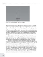
OK, that looks wrong! Where’s the nice soft shadow? Well, take a look at
the light size. The default area light is 1 meter square, and remember
that we moved the light high up above the object. So the area light is a
small light pretty far away from the subject. We know that the sky is
much larger than 1 meter. We need to make our area light much larger to
match. Let’s size it up to about 15 meters square and bring it down so
that it’s about six meters off the ground. Remember, this area light
should be pointing directly downward or have a pitch of 90 degrees. You
could also make the pitch –90 degrees. Area lights work equally well in
both directions.
···································
Tips, Tricks ’n’ Tutes
361
Figure 25.28
Well, that certainly increased render times. This frame took 1:22 to ren
-
der. But look at the beautiful soft shadows we are starting to get beneath
the bongos.
Note: Area lights and linear lights tend to create some “noise”
that is especially apparent during animated sequences. Higher
quality settings will reduce this noise, but you should always have
Shading Noise Reduction enabled in the Global Illumination panel
if you are using one of these light types. And don’t forget the pre-
vious note about G2!!
Note: Shading Noise Reduction works by blurring the diffuse
channel of objects. Keep this in mind when using diffuse maps;
they will become softer.
Chapter 25
······································
362
Figure 25.30
Figure 25.29
This is the same image as the previous one but with Shading Noise
Reduction enabled. It adds only a few seconds to each pass of the render
but really improves shadow quality by removing noise. If you closely
compare this image with the previous one, you will find that the fuzzi
-
ness of the shadow map is also softer and more pleasing.
Manual “Light Bowl” Setup
A single area light over the subject will often suffice as a soft sky fill
source. But there are times when you need a sky fill that is shaped more
like the sky. You can use global illumination, and we’ll get to that later,
but first let’s look at a slightly cheaper (and slightly less beautiful) tech
-
nique I call the area light bowl. It’s a simple setup, really. You add two,
three, four, five, or however many area lights you want in an inverted
bowl shape to light your scene from more than one plane. Remember,
the sky wraps around like an inverted bowl so this is more like a real sky
than a single area light pointing downward. It’s sort of a poor man’s
Backdrop Only global illumination. Bear in mind that as you add more
area lights, your rendering times may increase dramatically, so try to get
away with as few area lights as possible. Also keep in mind that as you
add more area lights to your “light bowl,” the light intensities will add
up, so as you add more lights, you will need to proportionately decrease
the intensity of every light in the “bowl.”
···································
Tips, Tricks ’n’ Tutes
363
Figure 25.31
Here are the respective rendering times for each of the light bowl set
-
ups I used. The renders were done with Enhanced Medium antialiasing
on a single-processor Athlon XP1800.
2 Lights 2:36
3 Lights 3:35
4 Lights 4:54
5 Lights 5:56
Figure 25.32 shows the
final five-light “light
bowl” area light setup.
The shadows are beauti
-
ful and soft. And really, a
render time under six
minutes is not exactly
outrageous. Obviously,
the more area lights you
add, the softer and more
pleasing the soft shadows will be. Since smaller area lights render more
quickly than large ones, you might try adding an array of smaller area
lights without too much of an increase from this time. But smaller area
lights become more directional, creating harder shadows, so be careful.
The nice thing is that you would have a more natural hemisphere shape
instead of the blocky shape produced by the five-light setup. But it’s a lot
of work to set up a large array of lights in a hemisphere, isn’t it? Not any
more. Looks like a job for luxigons!
A “Light Bowl” Using Luxigons
Luxigons are an absolutely prime tool for exactly this type of setup.
When you have a situation where you need to create a large array of
lights in specific positions, the fact is LightWave’s Modeler is so mature
and robust that it is much easier to create, clone, and reposition poly
-
gons than lights. So do it. Make all your polygons in Modeler in the
positions where you want lights. Import them into Layout and convert
luxigons. Done.
First, open up a fresh Modeler. Now for an array of area lights, I’d
like to have a nice, fairly even bowl of maybe 12 lights. More area lights
than that are really not necessary since each area light already behaves
like an array of point lights. As long as the coverage is even, the soft
shadows will be very nice indeed.
I start by creating a ball using the Numeric panel. I make the ball
have six sides and four segments.
Chapter 25
······································
364
Figure 25.32
···································
Tips, Tricks ’n’ Tutes
365
We’re only going to use the top hemisphere for our luxigon array, so let’s
remove the bottom half.
An important consideration when creating a luxigon array is the direc
-
tion of the polygon normals. The initial rotation of the light will be
whatever the direction of the normal is. We want all our lights pointing
Figure 25.33
Figure 25.34
inward, so let’s select all the polygons and flip them so that the normals
are facing inward.
Now there are a couple of ways to define what the light settings will be.
The first is done in Modeler, but the second method, done in Layout,
allows you to include many more settings not available in Modeler. Let’s
look at both methods.
For the Modeler
method, simply go to the
Construct panel, click the
Additional drop-down, and
select the plug-in Add
Luxigons. You will see the
following panel appear.
Using the Attach Light to Polygon panel, you can define the lights’
type, color, and intensity as well as whether shadows are on or off. If you
are using a spotlight, you will also get the option to use either ray-traced
shadows or shadow maps. I have set the light color to 6000 degrees Kel
-
vin and set the intensity to 5%. Remember, the light intensities are
additive, so 12 lights at 5% will produce sufficient illumination.
The second method of defining the light properties is to already
have one light in Layout before loading in the luxigon object. When you
convert luxigons in Layout, you will be presented with the option to
Chapter 25
······································
366
Figure 25.35
Figure 25.36
clone any light in Layout. As you can see, this is a great way to set up
very specific and detailed light settings for use with luxigons.
So now that we have our luxigon object set up, save it somewhere
and send it to Layout or, if you don’t use the Hub, switch to Layout and
load the luxigon object you just created.
In Layout, make sure you have your luxigon object selected. Select
your Generics drop-down in the Scene tab. There you will see the
ConvertLuxigons command. Select ConvertLuxigons.
When the Add Luxigon Lights dialog box pops up, you have two options.
You give all the lights a name and you can choose whether or not to
clone an existing light in the scene. If you choose not to clone a light, the
light settings from Modeler will be used for all the luxigon-generated
lights. If, on the other hand, you prefer a more complex light setup, you
can create a light in Layout and use that light as the template for all the
luxigon light properties. Say you wanted a projection image in the light,
or you wanted to specify object exclusion or perhaps a falloff option.
You’d set up a light in Layout with all the settings you want, then when
you convert luxigons, select that light as the clone object. All the
luxigon-generated lights will now have the same settings as that first
light you set up.
···································
Tips, Tricks ’n’ Tutes
367
Figure 25.37
In this case, though, we’re satisfied with the simple settings we
were able to set in Modeler, so we’ll just go ahead and hit OK. Let’s see
what we’ve come up with.
As you can see, there is an array of area lights coincident with the poly-
gons of the light bowl luxigon object. If you look at the Scene Editor,
you’ll also see that all the lights are parented to the luxigon object, so
you can move the whole array together by selecting and moving the
object. But the object may become cumbersome. In order to remove the
object, yet keep all the parenting info, it’s easy to replace the object with
a null under the Item tab’s Replace button.
Chapter 25
······································
368
Figure 25.39
Figure 25.38
And now, a quick render to see how our luxigon setup worked.
OK, that wasn’t exactly a quick render at 15:08, but the soft shadows
sure look nice. Of course, you don’t have to use 12 area lights either.
This image doesn’t show much better lighting quality than the five-light
setup we did (which took a third of the time to render).
A Light Bowl Using Distant Lights
We know that ray-traced lights such as distant lights render much more
quickly than area lights. We also know that an area light behaves like an
array of ray-traced lights. So rather than creating an array of area lights,
let’s try an array of ray-traced lights. First, go back into Modeler and
open up the luxigon object we created previously. Access the Add
Luxigons plug-in and this time use the settings in Figure 25-41:
This will ensure that the lights are distant lights, with ray tracing on, an
intensity of 5% each, and a light, sky blue color.
In Layout, load the light bowl object, and then convert luxigons,
being sure not to clone any of the lights in the scene.
···································
Tips, Tricks ’n’ Tutes
369
Figure 25.40
Figure 25.41
Don’t forget to open up the Object
Properties panel of the luxigon object
and make sure it’s unseen by cameras
and rays, and does not cast, receive, or
self shadow (or replace it with a null
object).
Now let’s take a look at the shadow
quality.
The shadows from the distant
light array are pretty mar
-
ginal. So let’s use a variation
of the “spinning light” trick to
improve the quality of the
soft shadows without increas
-
ing render times.
First, make sure the luxigon object has a keyframe at frame 0, with a
heading of 0 degrees. Then, rotate the luxigon object on its heading 720
degrees on frame 1 and make a keyframe. Open up the Graph Editor,
Chapter 25
······································
370
Figure 25.42
Figure 25.44
Figure 25.43
being sure the luxigon object is selected, and set Post Behavior to
Repeat, which makes the object rotate twice per frame.
Next, we set Motion Blur to 50% and Antialiasing to Enhanced Low
in our Camera Properties panel. This has the effect of spreading the
motion blur passes over 50% of the motion from the previous frame (720
degrees). Now in every frame, the array will rotate 50% of 720 degrees
each frame; in other words, 360 degrees. Render by pressing F9 and see
what you get (see Figure 25.45).
That provided a
slight improvement
in image quality with
no increase in render
time. We can
improve the shadow
quality even more by
increasing the anti-
aliasing quality. Of
course, that means
more render passes,
which means higher
render times. But so
far the render is
under a minute, so
let’s see an image
with Enhanced High
dithered antialiasing.
The shadow
quality is quite
improved from
Enhanced Low and
the render was under
4 minutes. Not quite
the quality of area
lights, but definitely
a time-saver. Of
course, there are no
shadows in Light
-
Wave superior to those created by LightWave’s Global Illumination tool.
···································
Tips, Tricks ’n’ Tutes
371
Figure 25.46
Figure 25.45
Global Illumination (Backdrop Only Radiosity)
Now we get to global illumination. Contrary to public belief, global illu
-
mination (and radiosity) does not necessarily have to signify outrageous
render times. There are a number of settings you can alter to improve
speed. In this case, we’re going to try out LightWave’s built-in solution
to our “light bowl” setup, and that is radiosity in Backdrop Only mode.
The best argument for this type of solution for a skylight fill is that
the shadows are very close to perfect. Global illumination in Background
Only mode works like an accessibility plug-in. In other words, object sur
-
faces are illuminated based on whether or not the sky backdrop can
“see” them. So portions of the surfaces that face the sky will be fully
illuminated with the radiosity intensity. Portions of the surfaces that are
partly occluded from the sky backdrop will be partly illuminated and por
-
tions of the surface that are completely occluded from the sky backdrop
will receive no illumination from it.
There are a number of ways to do a sky fill light using radiosity in
Backdrop Only mode. Let’s go ahead and turn radiosity on and set it to
Backdrop Only. Open your Light Properties panel and click the Global
Illumination button. In the Global Illumination panel, turn on Shading
Noise Reduction and Enable Radiosity. Set Type to Backdrop Only,
Intensity to 75%, and Rays Per Evaluation to3x9.Ifind that having
Shading Noise Reduction turned on often allows me to decrease the
Rays per Evaluation to3x9,thereby improving render times.
The next thing to do is to set up a backdrop. Open up your Backdrop
panel.
Chapter 25
······································
372
Figure 25.47
Figure 25.48
By default, LightWave sets the background to black, or 0, 0, 0. Black will
emit no light for a radiosity setup, so if we expect to get some skylight
illumination out of the backdrop we’ll have to make some changes. First,
let’s change the color. Click on the color box next to Backdrop Color.
When the LightWave color pick er pops up, select the Kelvin tab.
Note: To use the LightWave color picker instead of the default
Windows color picker, open your General Options panel in Layout
by hitting the “o” button, then next to Color Picker, change Default
to LW_ColrPikr by clicking and dragging the drop-down.
I always use the Kelvin tab when selecting skylight, since skylight is
usually measured in Kelvin degrees. On the K elvin scale, skylight
ranges between 10,000 and 20,000 degrees. Since LightWave’s color
picker only goes up to 11,000, I choose that number. So select 11,000
Kelvin as your color temperature and close the color picker. Now let’s
take a look at the render.
Now that is a fine-looking soft
shadow in anyone’s book. And
at 3:20 it’s not exactly a harsh
render time. Granted, there
are no textures and AA was set
to Enhanced Low, but it’s still
not difficult to argue the bene
-
fit of such beautiful shadows
for a reasonable increase in
render time.
There are a couple of other back
-
ground options to consider here as
well. For one, you can use
LightWave’s built-in Gradient Back
-
drop tool.
The big advantage to using a gra
-
dient backdrop is that you can vary
the background color. This is much
more realistic since background
radiosity comes from the ground as
···································
Tips, Tricks ’n’ Tutes
373
Figure 25.50
Figure 25.49
well as the sky. Also, you don’t really want sky fill color coming from
below in most cases. It would be nice to have blue above and green or
brown below to imply dirt or greenery (or whatever is on the ground in
the nearby environment). For details about setting up LightWave’s
built-in Gradient Backdrop, take a look through the manual.
As you can see, the
one real disadvantage
to the built-in Gradi
-
ent Backdrop is that
you don’t have any
control over where
the ground meets the
sky. If you are work
-
ing on a scene in
which the horizon is
not visible, this is not
a problem, and the
built-in Gradient
Backdrop is a very
quick backdrop solution. But if you want more control over your back-
drop and especially over the position of the horizon, just look a little
lower on the Backdrop panel.
Click on the Add Environment button and select Textured Environ-
ment from the drop-down.
Now double-click on the plug-in and a
small interface will open at the bot
-
tom of the panel.
Chapter 25
······································
374
Figure 25.51
Figure 25.52
Figure 25.53
Select the Y axis and click on the Texture button to open a new
interface.
In the Texture Editor,
change Layer Type to
Gradient and switch
Input Parameter to Pitch.
This ensures that your
gradient will be applied
so that the top of the gra
-
dient in this panel is at
the top of the backdrop
and the bottom of the
gradient is at bottom of
the backdrop. Now all
you have to do is set
some parameters in the
gradient and choose the
colors. I like to put two
parameters where I want
the horizon to be, then make a sky color and a ground color. Of course,
this is a simple setup. You can make the gradient as complex as you like.
Because I have con-
trol over exactly where
the horizon exists, I can
make sure it is not visible
above the ground plane
polygon if I wish.
One of the really
useful features of a gradi
-
ent background is that
you can alter the amount
of illumination by using
the Scale Values slider on
the right of the gradient
panel. If your render
turns out too bright, sim
-
ply scale the values
down. If too dark, scale
them up. Keep in mind that you can scale your color values above 255,
which provides much more illumination than was possible in the past.
Remember, we’re dealing with floating-point colors now. We are no
···································
Tips, Tricks ’n’ Tutes
375
Figure 25.55
Figure 25.54
longer limited to the 0 to 255 range. A value higher than 255 means
increased illumination. This value scaling works as a multiplier to the
radiosity intensity value you set in the Global Illumination panel.
As you can see in Figure
25.56, I have used a gradient
backdrop but placed the hori
-
zon just below my polygon
ground plane. The illumina
-
tion is good; I scaled the
values down a little, but I
could have just as easily
turned down the Intensity
setting in the Global Illumina
-
tion panel. The soft shadows
are very nice.
Using Textured Environ-
ment is one of my favorite
ways of creating a Backdrop
Only radiosity setup.
Sky Fill Using an Image
Of course, when using Textured Environment, you have the option of
using any textures available to you in the Surface Editor. That means not
only gradient but procedural and image textures. If you want some real-
istic-looking sky lighting, including variations in blue and white from
clouds and atmospheric changes or perhaps reds and oranges from sun
-
sets and whatnot, you can always add an image to Textured Environ
-
ment. You’d probably
use a cylindrical or
spherical map, maybe
something like the fol
-
lowing image.
Simply use an
image instead of a gradi
-
ent. For an image like
this, I like to increase
the Image Wrap setting
to 3 so the image isn’t
so stretched. You don’t
have to use an HDRI
image; any old image
Chapter 25
······································
376
Figure 25.56
Figure 25.57
will do. Background Only radiosity will use the background colors of the
image to calculate.
Because this is
not an HDRI image,
the illumination
range will not be as
high. In other words,
regular 8-bit RGB
images are capable of
only a certain level of
illumination. This
illumination level is
clamped at the white
point of the image.
For more precise
lighting, you will
wish to use the
HDRI method discussed later in this chapter. The nice thing about this
method is that it gives you subtle color variations in the lighting, which
are more natural than the smooth, homogeneous colors created by
gradients.
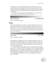
It is possible, however, to squeeze more illumination out of a regular
8-bit background image, but this method comes at a price.
Open your Image Editor, select
the background image, and select
the Editing tab (Figure 25.59).
Notice you have slider control
over brightness, contrast, hue, satu
-
ration, and gamma. By simply
sliding the Brightness control to
make the image brighter, the image
will provide a higher level of illumi
-
nation for a radiosity solution. I was
able to achieve some interesting
results by also fiddling with the sat
-
uration and contrast settings. Both
saturation and contrast helped me
maintain color in the image while
brightening it.
···································
Tips, Tricks ’n’ Tutes
377
Figure 25.59
Figure 25.58
If you look at the
quality of the back
-
ground image, you
will conclude that
this technique is
probably best used in
a situation where the
background is not
visible in the shot.
Radiosity Setups
Radiosity is the best thing to come to CG lighting since the invention of
ray-traced shadows. It embodies lighting that appears physically accu-
rate and real. First, let’s recall exactly what radiosity is.
Radiosity Recap
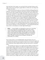
Radiosity, specularity, reflection, refraction, and caustics are all the redi-
rection of light. The main difference is how we see that redirected light
when it contacts a surface. In the case of radiosity, we are discussing a
diffused reflection of light, usually from one surface onto another sur
-
face. Radiosity can reflect many times. This is known in LightWave as
multi-bounce radiosity.
Note: If you have ever looked at two mirrors that are facing
each other, you have likely noticed how the image (and therefore
the light reflected from the surface) bounced back and forth into
infinity or until the light diffused enough that it became invisible.
This is radiosity in action. Although LightWave makes a distinction
between reflected images and reflected (bounced) light, they are
the same in the real world.
Earlier versions of LightWave were capable only of one radiosity bounce.
This kept calculations and render times relatively reasonable. Higher
order bounces increase render times exponentially, although more
bounces are more realistic and generally better looking. Here’s our bald
Chapter 25
······································
378
Figure 25.60
man again to demonstrate radiosity. Both images in Figure 25.61 use a
single spotlight as the key light source. The only difference is that sin
-
gle-bounce radiosity is turned on for the image on the right.
Radiosity generally distinguishes itself by the way it apparently “picks
up” the color from a surface off which it reflects. Sunlight that is
reflected off a yellow wall then becomes yellow reflected light. This is
caused not by “picking up” color as it appears, but, in fact, by “dropping
off” color. The yellow wall absorbs most of the blue wavelengths of the
sunlight, leaving only the red and green to be reflected. Red and green
light mix to make yellow.
Ambient Intensity and Radiosity
Ambient intensity has generally been viewed by lighting artists as a
blight and a plague on lighting, something to be ignored, scoffed at,
insulted, and spat upon except in the most extreme of time-constraint
situations. Even then, ambient intensity would be added reluctantly, with
dismay and disgust, sometimes forcing the artist to shower afterward to
wash off the “ickiness” of the debasement he had just performed.
Perhaps I embroider the facts slightly, but ambient lighting is very
unnatural and will make your lighting look flat. In a 3D environment, this
is not considered desirable.
But with the addition of radiosity into LightWave a couple of years
ago, ambient intensity has gained a new foothold in our lighting plans.
This is because ambient intensity, when coupled with radiosity, takes on
a new function that doesn’t just wash out and flatten our images. It actu
-
ally improves them and saves us render time. So you don’t have to flip
through the LightWave manual for this tidbit, here’s a quote:
···································
Tips, Tricks ’n’ Tutes
379
Figure 25.61
“Ambient light … is not directly added to surface points that are
shaded with radiosity — where radiosity rays originate. However, it
is added to points that are shaded without radiosity — where
radiosity rays hit a surface. If not for this, a new evaluation point
would be spawned at the hit points and render time would explode.
“Ambient light will still brighten every surface, but only indi
-
rectly, after bouncing off other surfaces. Thus it can simulate light
that would have come from further radiosity bounces.”
If this sounds confusing, bear with me. You’ll see just what this means
when we use ambient intensity with radiosity next.
Backdrop Only
LightWave’s radiosity in Backdrop Only mode is an extr emely useful
feature. It is, perhaps, the most useful of all the radiosity modes. For one
thing, it is the quickest-rendering of all the radiosity modes because it
does not calculate any light bounces. Illumination from the background
simply illuminates whatever surfaces are “visible” to the background.
Calculations are much simpler and quicker than single-bounce or
multi-bounce calculations. Further, the soft shadows created by Back-
drop Only radiosity are vastly superior to any soft shadows created by
any other method, technique, or “cheat” such as spinning lights, fuzzy
shadow maps, and even area lights.
Creating a Backdrop Only
radiosity setup in LightWave is a sim
-
ple and straightforward process.
Simply open your Light Properties
panel, click on the Global Illumination
button, select Enable Radiosity (and
Shading Noise Reduction), and set the
radiosity type to Backdrop Only.
Now that we are using Backdrop
Only mode, we’ll need a backdrop to
illuminate the scene. By default,
LightWave’s background is black.
Black will definitely not produce any
illumination for our scene. We have
several options: We can use
LightWave’s built-in Gradient Backdrop, we can add LightWave’s Tex
-
tured Environment and add an image, gradient, or procedural texture as
our backdrop (both of these methods are covered earlier in this chapter),
Chapter 25
······································
380
Figure 25.62
or we can just change the backdrop
color. For the simplest example of
Backdrop Only radiosity, we’ll just do
that. Open up your Backdrop sub-tab
in the Effects panel and select a nice
color for your backdrop. It doesn’t
matter what color for the purposes of
this tutorial, as long as the color is
bright enough to illuminate the scene.
I selected a color temperature of
11,000 from the Kelvin color picker.
By default, LightWave has one
distant light in the scene at 100%.
Turn that light off, and enable Ray
Trace Shadows in your Render
Options panel. Hit F9 and take a look
at those beautiful soft shadows.
As the least “expensive” render of the radiosity modes, it’s not too diffi
-
cult to see why Backdrop Only mode might get used a great deal for
photo-real work.
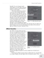
Monte Carlo
Monte Carlo is the Cadillac of radiosity modes in LightWave. With
Monte Carlo you can specify multiple light bounces that dramatically
improve the photo-realism of your lighting. There is no interpolation or
estimation here. Naturally, a dramatic increase in render time comes
with the dramatic improvement in visual quality. The big difference
···································
Tips, Tricks ’n’ Tutes
381
Figure 25.64
Figure 25.63