Introduction to AutoCAD 2008 2D and 3D Design phần 5 docx
Bạn đang xem bản rút gọn của tài liệu. Xem và tải ngay bản đầy đủ của tài liệu tại đây (8.64 MB, 38 trang )
140 Introduction to AutoCAD 2008
2. The section follows the general rule that parts such as screws, bolts,
nuts, rivets, other cylindrical objects, webs and ribs and other such
features are shown within sections as outside views.
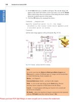
Third example – Associative hatching (Fig. 8.5)
Fig. 8.5 shows two end view of a house. After constructing the left-hand
view, it was found that the upper window had been placed in the wrong
1
2
3
4
Pick Point
Pick Point
Add centre line
after hatching
Hatch Pattern
ANSI31 at
Angle
= 0
Scale
= 1.5
left-click on
Preview button
if satisfied
left-click on
OK button
Change Hatch
Angle to 90
Pick Point
Pick Point
Fig. 8.4 Second example –
hatching rules for sections
Fig. 8.3 First example – Hatching
Ch08-H8512.qxd 4/4/07 6:45 PM Page 140
Hatching 141
position. Using the Move tool, the window was moved to a new position.
The brick hatching automatically adjusted to the new position. Such
Associative hatching is possible only if the check box against Associa-
tive in the Options area of the Hatch and Gradient dialog is ON – a tick
in the check box (Fig. 8.6).
Fourth example – Colour gradient hatching (Fig. 8.9)
Fig. 8.8 shows two examples of hatching from the Gradient sub-dialog of
the Hatch and Gradient dialog.
1. Construct two outlines each consisting of six rectangles (Fig. 8.9).
2. Click the Gradient tool icon in the 2D Draw control panel
(Fig. 8.7) or in the Draw toolbar. In the Hatch and Gradient dialog
which appears (Fig. 8.8) pick one of the gradient choices, followed
with a click on the Pick an internal point button. Click one of the
color panels in the dialog and when the dialog disappears, pick a single
area of one of the rectangles in the left-hand drawing, followed by a
click on the dialog’s OK button when the dialog reappears.
3. Repeat in each of the other rectangles of the left-hand drawing, chang-
ing the pattern in each of the rectangles.
4. Click the button ( ) to the right of the Color field, select a new colour
from the Select Color dialog which appears and repeat steps 3 and 4 in
the six rectangles.
The result is shown in Fig. 8.9.
Note
If the Two color radio button is set on (dot in circle) the colours involved
in the gradient hatch can be changed by clicking the button marked with
three dots ( ) on the right of the colour field. This brings a Select Color
dialog on screen, which offers three choices of sub-dialogs from which to
select colours.
End view of house
before moving
the upper
window
frame
After moving frame
hatching adjusts
to its new
position
Fig. 8.5 Third example –
Associative hatching
Fig. 8.6 Associative hatching set
On in the Hatch and Gradient
dialog
Fig. 8.7 The Gradient Hatch
tool icon from the 2D Draw
control panel
Ch08-H8512.qxd 4/4/07 6:45 PM Page 141
142 Introduction to AutoCAD 2008
Fifth example – Advanced hatching (Fig. 8.12)
If the arrow at the bottom right-hand corner of the Hatch and Gradient
dialog is clicked (Fig. 8.10) the dialog expands to show the Island
Display selections (Fig. 8.11).
1. Construct a drawing which includes three outlines as shown in the left-
hand drawing of Fig. 8.12 and copy it twice to produce three identical
drawings.
Fig. 8.8 The Hatch and
Gradient dialog
Fig. 8.9 Fourth example – Colour
Gradient hatching
Fig. 8.10 The More Options
arrow of the Hatch and
Gradient dialog
Ch08-H8512.qxd 4/4/07 6:45 PM Page 142
2. Select the hatch pattern HONEY at an angle of 0 and scale 1.
3. Click in the Normal radio button of the Island display style area.
4. Pick a point in the left-hand drawing. The drawing hatches as shown.
5. Repeat in the centre drawing with the radio button of the Outer style
set on (dot in button).
6. Repeat in the right-hand drawing with Ignore set on.
Sixth example – Text in hatching (Fig. 8.13)
1. Construct a pline rectangle using the sizes given in Fig. 8.13.
2. In the Text Style Manager dialog, set the text font to Arial and its
Height ϭ 25.
3. Using the Dtext tool enter the text as shown central to the rectangle.
4. Hatch the area using the HONEY hatch pattern set to an angle of 0
and scale of 1.
The result is shown in Fig. 8.13.
Note
Text will be entered with a surrounding boundary area free from hatching,
providing the Advanced Normal radio button is set on.
Hatching 143
Fig. 8.11 The Island display
style selections in the expanded
Hatch and Gradient dialog
pick points
Normal Outer Ignore
Fig. 8.12 Fifth example –
Advanced hatching
90
275
AutoCAD 2007
Fig. 8.13 Sixth example – Text in
hatching
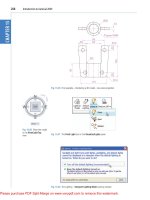
Seventh example – Advanced hatching (Fig. 8.20)
1. From the Layers control panel open the Layer list with a click on the
arrow to the right of the layers field.
2. Note the extra added layer (HATCH) in Fig. 8.14.
3. With the layer 0 current, construct the outline as given in Fig. 8.15.
4. Make layer Text current and construct the lines as shown in Fig. 8.16.
Ch08-H8512.qxd 4/4/07 6:45 PM Page 143
144 Introduction to AutoCAD 2008
Fig. 8.14 Seventh example – the
layers setup for the advanced
hatch example
Fig. 8.15 Seventh example –
construction on layer 0
Fig. 8.16 Seventh example –
construction on layer Te x t
Ch08-H8512.qxd 4/4/07 6:45 PM Page 144
5. Make the layer HATCH current and add hatching to the areas shown
in Fig. 8.17 using the hatch patterns ANGLE at scale 2 for the roof
and BRICK at a scale of 0.75 for the wall.
6. Finally turn the layer Text off. The result is given in Fig. 8.18.
Hatching 145
Fig. 8.17 Seventh example –
construction on layer HATCH
Fig. 8.18 Seventh example – the
finished drawing
Revision notes
1. A large variety of hatch patterns are available when working with
AutoCAD 2008.
2. In sectional views in engineering drawings it is usual to show items such
as bolts, screws, other cylindrical objects, webs and ribs as outside views.
Ch08-H8512.qxd 4/4/07 6:45 PM Page 145
146 Introduction to AutoCAD 2008
Fig. 8.19 Exercise 1 – a pictorial
view
Fig. 8.20 Exercise 1
3. When Associative hatching is set on and an object is moved within a
hatched area, the hatching accommodates to fit around the moved object.
4. Colour gradient hatching is available in AutoCAD 2008.
5. When hatching takes place around text, a space around the text will be
free from hatching.
Exercises
1. Fig. 8.19 shows a pictorial drawing of the component shown in the three-
view orthographic projection in Fig. 8.20. Construct the three views, with
the front view as a sectional view based on the section plane A-A.
2. Construct the three-view orthographic projection in Fig. 8.21 to the
given dimensions with the front view as the sectional view A-A.
Fig. 8.21 Exercise 2
Ch08-H8512.qxd 4/4/07 6:45 PM Page 146
3. Construct the drawing in Stage 5 following the descriptions of stages
given in Fig. 8. 22.
Hatching 147
Stage 1
Construct word
on Layer 0 and
offset on Layer 1
Stage 2
Hatch on Layer
HATCH01
Hatch with SOLID
Stage 3
Turn Layer 0 off
Turn HATCH01 off
Add lines as shown
Stage 4
Turn HATCH02 on
HATCH with ANSI31
at Angle 135 and
Scale 40
Turn HATCH02 off
Stage 5
Turn Layer 0 off
Turn HATCH01 on
Fig. 8.22 Exercise 3
4. Fig. 8.23 is a front view of a car with parts hatched. Construct a
similar drawing of any make of car, using hatching to emphasise the
shape.
Fig. 8.23 Exercise 4
5. Working to the notes given with the drawing in Fig. 8.24, construct the
end view of a house as shown. Use your own discretion about sizes for
the parts of the drawing.
6. Working to dimensions of your own choice, construct the three-view
projection of a two-storey house as shown in Fig. 8.25.
7. Construct Fig. 8.26 as follows:
(a) On layer Text, construct a circle of radius 90.
(b) Make layer 0 current.
Ch08-H8512.qxd 4/4/07 6:45 PM Page 147
(c) Construct the small drawing to the details as shown and save as a
block with a block name shape (see Chapter 9).
(d) Call the Divide tool by entering div at the command line:
Command: enter div right-click
Select object to divide: pick the circle
Enter number of segments or [Block]: enter b right-click
148 Introduction to AutoCAD 2008
Hatch Pattern
ANGLE at
Scale
= 0.025
Angle
= 0
Hatch Pattern
AE-BBB at
Scale
= 0.025
Angle
= 0
Hatch Pattern
SAND
Scale
= 0.1
Angle
= 0
Hatch Pattern
BRICK at
Scale
= 0.8
Angle
= 0
Hatch Pattern
BRSTONE
Scale
= 0.7
Angle
= 0
Hatch Pattern
AR-BBB at
Scale
= 0.4
Angle
= 0
Windows are
55
× 35 with
bars 1 and 2
wide
70
25
25 160
110
170
180
60
5
5
10
Fig. 8.24 Exercise 5
Fig. 8.25 Exercise 6
Ch08-H8512.qxd 4/4/07 6:45 PM Page 148
Enter name of block to insert: enter shape right-click
Align block with object? [Yes/No] ϽYϾ: right-click
Enter the number of segments: enter 20 right-click
Command:
(e) Turn the layer Text off.
Hatching 149
R70
30
35
40
Hatch with
STARS
Scale = 0.75
Fig. 8.26 Exercise 7
Ch08-H8512.qxd 4/4/07 6:45 PM Page 149
150
Garage door
Single bed
Table WC Bath Shrub
Double bed
Chair Chair2 Chair3
2.5
m window 2 m window Main door Room door
Fig. 9.1 First example – Blocks –
symbols to be saved as blocks
CHAPTER 9
Blocks and Inserts
Aims of this chapter
1. To describe the construction of blocks and wblocks (written blocks).
2. To introduce the insertion of blocks and wblocks into other drawings.
3. To introduce the use of the DesignCenter palette.
4. To explain the use of the Explode and Purge tools.
Introduction
Blocks are drawings which can be inserted into other drawings. Blocks
are contained in the data of the drawing in which they have been con-
structed. Wblocks (written blocks) are saved as drawings in their own
right, but can be inserted into other drawings if required.
Blocks
First example – Blocks (Fig. 9.3)
1. Construct the building symbols as shown in Fig. 9.1 to a scale
of 1:50.
Ch09-H8512.qxd 3/26/07 1:14 PM Page 150
Blocks and Inserts 151
2. Left-click the Make tool in the Block Attributes control panel
(Fig. 9.2). The Block Definition dialog (Fig. 9.3) appears. To make a
block of the Double bed symbol drawing:
(a) Enter double bed in the Name field.
(b) Click the Select objects button. The dialog disappears. Window the
drawing of the double bed. The dialog reappears. Note the icon of
the double bed in the top right-hand corner of the dialog.
(c) Click the Pick Point button. The dialog disappears. Click a point
on the double bed drawing to determine its insertion point. The
dialog reappears.
(d) If thought necessary enter a description in the Description field of
the dialog.
(e) Click the OK button. The drawing is now saved as a block in the
drawing.
Fig. 9.2 Click Make tool icon in
the Block Attributes control
panel
Fig. 9.3 The Block Definiton
dialog with entries for the
double bed
3. Repeat steps 1 and 2 to make blocks of all the other symbols in the
drawing.
4. Open the Block Definition dialog again and click the arrow on
the right of the Name field. Blocks saved in the drawing are listed
(Fig. 9.4).
Ch09-H8512.qxd 3/26/07 1:14 PM Page 151
152 Introduction to AutoCAD 2008
Inserting blocks into a drawing
There are two methods by which symbols saved as blocks can be inserted
into another drawing.
Example – first method of inserting blocks
Ensuring that all the symbols saved as blocks using the Make Block tool
are saved in the data of the drawing in which the symbols were con-
structed, erase the drawings of the symbols and in their place construct
the outline of the plan of a bungalow to a scale of 1:50 (Fig. 9.5). Then:
Fig. 9.4 The popup list in the
Name field of the Block
Definition dialog showing all
blocks saved in the drawing
16 m
7
m
4 m
12
m
Fig. 9.5 First example – inserting
blocks. Outline plan
Ch09-H8512.qxd 3/26/07 1:14 PM Page 152
Blocks and Inserts 153
1. Left-click the Insert Block tool icon in the 2D Draw control panel
(Fig. 9.6) or the Insert Block tool in the Draw toolbar. The Insert
dialog appears on screen (Fig. 9.7). From the Name popup list select
the name of the block which is to be inserted, in this example the
2.5 window.
2. Make sure the checkbox against Explode is off (no tick in box). Click
the dialog’s OK button, the dialog disappears. The symbol drawing
appears with its insertion point at the intersection of the cursor hairs
ready to be dragged into its position in the plan drawing.
3. Once all the block drawings are placed, their positions can be adjusted.
Blocks are single objects and can thus be dragged into new positions
as required under mouse control. Their angle of position can be
amended at the command line, which shows:
Command:
INSERT
Specify insertion point or [Basepoint/Scale/X/Y/Z/Rotate/PScale/
PX/PY/PZ/PRotate]: enter r (Rotate) right-click
Specify insertion angle: enter 180 right-click
Specify insertion point: pick
Command:
Selection from these prompts allows scaling, stretching along any axis,
previewing, etc. as the block is inserted.
4. Insert all necessary blocks and add other details as required to the plan
outline drawing. The result is given in Fig. 9.8.
Example – second method of inserting blocks
1. Save the drawing which includes all the blocks to a suitable file name
(e.g. building_symbols.dwg). Remember this drawing includes data of
the blocks in its file.
Fig. 9.6 The Insert Block
tool icon in the 2D Draw
control panel
Fig. 9.7 The Insert dialog with its
Name popup list displaying the
names of all blocks in the drawing
Ch09-H8512.qxd 3/26/07 1:14 PM Page 153
154 Introduction to AutoCAD 2008
2. Left-click DesignCenter in the Standard Annotation toolbar
(Fig. 9.9) or press the Ctrlϩ2 keys. The DesignCenter palette appears
on screen (Fig. 9.10).
3. With the outline plan (Fig. 9.5) on screen the symbols can all be
dragged into position from the DesignCenter.
Fig. 9.8 Example – first method of
inserting blocks
Fig. 9.9 Selecting DesignCenter
from the Standard Annotation
toolbar
Fig. 9.10 The DesignCenter
with the double bed block dragged
on screen
Ch09-H8512.qxd 3/26/07 1:14 PM Page 154
Blocks and Inserts 155
Notes about DesignCenter palette
1. As with other palettes, the DesignCenter palette can be re-sized by
dragging the palette to a new size from its edges or corners.
2. Clicks on one of the three icons at the top-right corner of the palette
(Fig. 9.11) have the following results:
(a) Tree View Toggle – changes from showing two areas – a Folder
List and icons of the blocks within a file – to a single area showing
the block icons (Fig. 9.12).
(b) Preview – a click on the icon opens a small area at the base of the
palette, showing an enlarged view of the selected block icon.
(c) Description – a click on the icon opens another small area with a
description of the block.
Fig. 9.11 The icons at the top-
right corner of the
DesignCenter palette
Fig. 9.12 The results of a click on
Tree View Toggle
Fig. 9.13 The Explode check box
in the Insert dialog
The Explode tool
A block is a single object no matter from how many objects it was origi-
nally constructed. This enables a block to be dragged about the drawing
area as a single object.
A check box in the bottom left-hand corner of the Insert dialog is
labelled Explode (Fig. 9.13). If the check box is ticked, Explode will be
set on and when a block is inserted it will be exploded into the objects
from which it was constructed.
Ch09-H8512.qxd 3/26/07 1:14 PM Page 155
Another way of exploding a block would be to use the Explode tool
from the DASHBOARD palette (Fig. 9.14). A click on the icon or enter-
ing ex at the command line brings prompts into the command line:
Command:_explode
Select objects: pick a block on screen 1 found.
Select objects: right-click
Command:
And the picked object is exploded into its original objects.
The Purge tool
The Purge tool can be called by entering pu at the command line or from
Drawing Utilities in the File drop-down menu (Fig. 9.15). When the tool
is called the Purge dialog appears on screen (Fig. 9.16).
156 Introduction to AutoCAD 2008
Fig. 9.14 The Explode tool icon
in the DASHBOARD palette
Fig. 9.15 Calling Purge from the
Drawing Utilities sub-menu of
the File drop-down menu
Fig. 9.16 The Purge dialog
Ch09-H8512.qxd 3/26/07 1:14 PM Page 156
The Purge tool can be used to remove the data of blocks within a
drawing thus saving file space when a drawing which includes blocks is
saved to disk.
To use the tool, in its dialog click the Purge All button and a sub-
dialog appears naming a block to be purged. A click on the Yes button
clears the data of the block from the drawing. Continue until all blocks
that are to be purged are removed.
Take the drawing in Fig. 9.8 (page 154) as an example. If all the blocks
are purged from the drawing, the file will be reduced from 145 to 67 Kb
when the drawing is saved to disk.
Using the DesignCenter (Fig. 9.19)
1. Construct the set of electric/electronic circuit symbols shown in
Fig. 9.17 and make a series of blocks from each of the symbols.
2. Save the drawing to a file Fig17.dwg.
3. Open the acadiso.dwt template. Open the DesignCenter with a click
on its icon in the Standard Annotation toolbar.
4. From the Folder list select the file Fig17.dwg and click on Blocks
under its file name. Then drag symbol icons from the DesignCenter
into the drawing area as shown in Fig. 9.18. Ensure they are placed in
Blocks and Inserts 157
9 V
Battery
INT
PNP
PRswitch
Resistor
Varres
Varres2
Signal
Lamp
Varcapac
LDR LSR
NPN
Bridge
Capacitor
Diode Switch
Fuse
Fig. 9.17 Using the DesignCenter –
a set of electric/electronic symbols
Fig. 9.18 Using the DesignCenter
Ch09-H8512.qxd 3/26/07 1:14 PM Page 157
appropriate positions in relation to each other to form a circuit. If nec-
essary either Move and/or Rotate the symbols into correct positions.
5. Close the DesignCenter palette with a click on the x in the top left-hand
corner.
6. Complete the circuit drawing as shown in Fig. 9.19.
Note
Fig. 9.19 does not represent an authentic electronics circuit.
158 Introduction to AutoCAD 2008
6 V
Fig. 9.19 Using the DesignCenter –
the completed circuit
Wblocks
Wblocks or written blocks are saved as drawing files in their own right
and are not part of the drawing in which they have been saved.
Example – wblock (Fig. 9.20)
1. Construct a light emitting diode (LED) symbol and enter w at the
command line. The Write Block dialog appears (Fig. 9.20).
2. Click the button marked with three dots ( ) to the right of the File
name and path field and from the Browse for Drawing File dialog
which comes to screen select an appropriate directory. The directory
name appears in the File name and path field. Add LED.dwg at the
end of the name.
3. Make sure the Insert units is set to Millimetres in its popup list.
4. Click the Select objects button, window the symbol drawing and when
the dialog reappears, click the Pick point button, followed by selecting
the left-hand end of the symbol.
5. Finally click the OK button of the dialog and the symbol is saved in its
selected directory as a drawing file LED.dwg in its own right.
Note on the DesignCenter
Drawings can be inserted into the AutoCAD window from the Design-
Center by dragging the icon representing the drawing into the window
(Fig. 9.21).
Ch09-H8512.qxd 3/26/07 1:14 PM Page 158
When such a drawing is dragged into the AutoCAD window, the
command line shows a sequence such as:
Command:_INSERT Enter block name or [?] ϽFig26Ͼ: "Chap-
ter07\inserts\Fig25.dwg"
Blocks and Inserts 159
Fig. 9.20 Example – Wblock
Fig. 9.21 An example of a drawing
dragged from the DesignCenter
Ch09-H8512.qxd 3/26/07 1:14 PM Page 159
Specify insertion point or [prompts]: pick
Enter X scale factor Ͻ1Ͼ: right-click
Enter Y scale factor Ͻuse X scale factorϾ: right-click
Specify rotation angle Ͻ0Ͼ: right-click
Command:
Revision notes
1. Blocks become part of the drawing file in which they were con-
structed.
2. Wblocks become drawing files in their own right.
3. Drawings or parts of drawings can be inserted in other drawings with
the Block tool.
4. Inserted blocks or drawings are single objects unless either the
Explode check box of the Insert dialog is checked or the block or
drawing is exploded with the Explode tool.
5. Drawings can be inserted into the AutoCAD drawing area using the
DesignCenter.
6. Blocks within drawings can be inserted into drawings from the
DesignCenter.
Exercises
1. Construct the building symbols in Fig. 9.22 in a drawing saved as
symbols.dwg. Then using the DesignCenter construct a building
drawing of the first floor of the house you are living in, making use of
the symbols. Do not bother too much about dimensions because this
exercise is designed to practise using the idea of making blocks and
using the DesignCenter.
160 Introduction to AutoCAD 2008
wall
partition
door02
window01 window02
up_and_over
door01
compass
bath cooker
sink
basin
frig
WC
boiler
MH
tree01 tree02
stair
pipe
B
R
C
Fig. 9.22 Exercise 1
2. Construct drawings of the electric/electronics symbols in Fig. 9.17
(page 157) and save them as blocks in a drawing file electronics.dwg.
3. Construct the electronics circuit given in Fig. 9.23 from the file
electronics.dwg using the DesignCenter.
Ch09-H8512.qxd 3/26/07 1:14 PM Page 160
4. Construct the electronics circuit given in Fig. 9.24 from the file
electronics.dwg using the DesignCenter.
Blocks and Inserts 161
9 V
Fig. 9.23 Exercise 3
Fig. 9.24 Exercise 4
Ch09-H8512.qxd 3/26/07 1:14 PM Page 161
162
CHAPTER 10
Other types of file format
Aims of this chapter
1. To introduce Object Linking and Embedding (OLE) and its uses.
2. To introduce the use of Encapsulated Postscript (EPS) files.
3. To introduce the use of Data Exchange Format (DXF) files.
4. To introduce raster files.
5. To introduce Xrefs.
Object linking and embedding
First example – copying and pasting (Fig. 10.3)
1. Open any drawing in the AutoCAD 2008 window (Fig. 10.1).
2. Left-click Copy Link in the Edit drop-down menu (Fig. 10.1).
Fig. 10.1 A drawing in the
AutoCAD 2008 window showing
Copy Link selected from the
Edit drop-down menu
Ch10-H8512.qxd 4/4/07 6:47 PM Page 162
3. Click the AutoCAD 2008 Minimize button and open the Clipboard
viewer. The copied drawing appears in the clipboard (Fig. 10.2).
Other types of file format 163
Fig. 10.2 The drawing from
AutoCAD copied to the
Clipboard
Fig. 10.3 Example – copying and
pasting
4. Open Microsoft Word and click on Paste in the Edit drop-down menu
(Fig. 10.3). The drawing from the Clipboard appears in the Microsoft
Word document (Fig. 10.3).
5. Add text as required.
Ch10-H8512.qxd 4/4/07 6:47 PM Page 163
164 Introduction to AutoCAD 2008
Notes
1. It is not common practice to have a Clipboard window showing on
screen, since it usually works in the background. It is shown opened
here to display its use in acting as an agent for transposing drawings,
etc. from one application to another.
2. Similar results can be obtained using the Copy and Copy with Base
Point tools from the Edit drop-down menu of AutoCAD 2008.
3. The drawing could also be pasted back into the AutoCAD window –
not that there would be much point in doing so, but anything in the
Clipboard window can be pasted into other applications.
Second example – EPS file (Fig. 10.5)
1. With the same drawing on screen click on Export in the File drop-
down menu. The Export Data dialog appears (Fig. 10.4). Pick Encapsu-
lated PS (*.eps) from the Files of type popup list, then enter a suitable
file name (building.eps) in the File name field and click the Save button.
Fig. 10.4 The Export Data
dialog of AutoCAD 2008
2. Open a desktop publishing application. That shown in Fig. 10.5 is
PageMaker.
3. From the File drop-down menu click Place A dialog appears listing
files which can be placed in a PageMaker document. Among the files
Ch10-H8512.qxd 4/4/07 6:47 PM Page 164