Introduction to AutoCAD 2008 2D and 3D Design phần 1 potx
Bạn đang xem bản rút gọn của tài liệu. Xem và tải ngay bản đầy đủ của tài liệu tại đây (6.8 MB, 38 trang )
Introduction to AutoCAD 2008
Prelims-H8512.qxd 4/4/07 7:00 PM Page i
Prelims-H8512.qxd 4/4/07 7:00 PM Page ii
This page intentionally left blank
Introduction to AutoCAD 2008
2D and 3D Design
Alf Yarwood
AMSTERDAM • BOSTON • HEIDELBERG • LONDON • NEW YORK
OXFORD • PARIS • SAN DIEGO • SAN FRANCISCO
S
INGAPORE • SYDNEY • TOKYO
Newnes is an imprint of Elsevier
Prelims-H8512.qxd 4/4/07 7:00 PM Page iii
Newnes is an imprint of Elsevier
Linacre House, Jordan Hill, Oxford, OX2 8DP
30 Corporate Drive, Burlington, MA 01803
First edition 2007
Copyright © 2007. Alf Yarwood. Published by Elsevier Ltd. All rights reserved
The right of Alf Yarwood to be identified as the author of this work has been
asserted in accordance with the Copyright, Designs and Patents Act 1988
No part of this publication may be reproduced, stored in a retrieval system or
transmitted in any form or by any means electronic, mechanical, photocopying,
recording or otherwise without the prior written permission of the publisher
Permission may be sought directly from Elsevier’s Science & Technology Rights
Department in Oxford, UK: phone (ϩ44) (0) 1865 843830; fax (ϩ44) (0) 1865 853333;
email: Alternatively you can submit your request online by
visiting the Elsevier web site at and selecting
Obtaining permission to use Elsevier material
Notice
No responsibility is assumed by the publisher for any injury and/or damage to persons
or property as a matter of products liability, negligence or otherwise, or from any use or
operation of any methods, products, instructions or ideas contained in the material herein.
Because of rapid advances in the medical sciences, in particular, independent verification
of diagnoses and drug dosages should be made
British Library Cataloguing in Publication Data
A catalogue record for this book is available from the British Library
Library of Congress Cataloging-in-Publication Data
A catalog record for this book is available from the Library of Congress
ISBN: 978-0-75-068512-2
For information on all Newnes publications
visit our web site at
Typeset by Integra Software Services Pvt. Ltd, Pondicherry, India
www.integra-india.com
Printed and bound in Italy
0708091011 1110987654321
Prelims-H8512.qxd 4/4/07 7:00 PM Page iv
v
Contents
Preface xi
Registered Trademarks xii
PART I – 2D Design
1. Introducing AutoCAD 2008 3
Aim of this chapter 3
Opening AutoCAD 2008 3
The mouse as a digitiser 6
Palettes 7
The DASHBOARD palette 8
Dialogs 9
Buttons in the status bar 11
The AutoCAD coordinate system 12
Drawing templates 14
Method of showing entries in the command palette 16
Tools and tool icons 17
Another AutoCAD workspace 17
The DASHBOARD 18
Revision notes 20
2. Introducing drawing 22
Aims of this chapter 22
The 2D Drafting & Annotation workspace 22
Drawing with the Line tool 22
Drawing with the Circle tool 28
The Erase tool 30
Undo and Redo tools 31
Drawing with the Polyline tool 32
Revision notes 36
Exercises 37
3. Draw tools, Osnap and AutoSnap 40
Aims of this chapter 40
Introduction 40
The Arc tool 40
The Ellipse tool 42
Saving drawings 44
Osnap, AutoSnap and Dynamic Input 44
Prelims-H8512.qxd 4/4/07 7:00 PM Page v
Object Snaps (Osnaps) 45
Using AutoSnap 48
Dynamic Input 50
Examples of using other Draw tools 52
The Polyline Edit tool 56
Transparent commands 58
The set variable PELLIPSE 59
Revision notes 59
Exercises 60
4. Zoom, Pan and templates 65
Aims of this chapter 65
Introduction 65
The Aerial View window 67
The Pan tool 68
Drawing templates 69
Revision notes 79
5. The Modify tools 81
Aim of this chapter 81
Introduction 81
The Copy tool 81
The Mirror tool 83
The Offset tool 84
The Array tool 85
The Move tool 89
The Rotate tool 90
The Scale tool 91
The Trim tool 91
The Stretch tool 93
The Break tool 95
The Join tool 96
The Extend tool 97
The Chamfer and Fillet tools 98
Revision notes 99
Exercises 101
6. Dimensions and Text 106
Aims of this chapter 106
Introduction 106
The Dimension tools 106
Adding dimensions using the tools 107
Adding dimensions from the command line 109
The Arc Length tool 113
The Jogged tool 114
Dimension tolerances 114
Text 118
Symbols used in text 120
vi Contents
Prelims-H8512.qxd 4/4/07 7:00 PM Page vi
Checking spelling 121
Revision notes 123
Exercises 124
7. Orthographic and isometric 126
Aim of this chapter 126
Orthographic projection 126
First angle and third angle 128
Sectional views 129
Isometric drawing 131
Examples of isometric drawings 132
Revision notes 134
Exercises 135
8. Hatching 138
Aim of this chapter 138
Introduction 138
Revision notes 145
Exercises 146
9. Blocks and Inserts 150
Aims of this chapter 150
Introduction 150
Blocks 150
Inserting blocks into a drawing 152
The Explode tool 155
The Purge tool 156
Using the DesignCenter 157
Wblocks 158
Revision notes 160
Exercises 160
10. Other types of file format 162
Aims of this chapter 162
Object linking and embedding 162
DXF (Data Exchange Format) files 166
Raster images 167
External References (Xrefs) 169
Dgnimport and Dgnexport 172
Multiple Document Environment (MDE) 173
Revision notes 174
Exercises 175
11. Sheet sets 178
Aims of this chapter 178
Sheet sets 178
A sheet set for 62 Pheasant Drive 178
62 Pheasant Drive DWF 182
Contents vii
Prelims-H8512.qxd 4/4/07 7:00 PM Page vii
Revision notes 183
Exercises 183
12. Building drawing 186
Aim of this chapter 186
Building drawings 186
Floor layouts 190
Revision notes 190
Exercises 190
PART II – 3D Design
13. Introducing 3D modelling 195
Aims of this chapter 195
Introduction 195
The 3D Modeling workspace 195
Methods of calling tools for 3D modelling 196
The Polysolid tool 198
2D outlines suitable for 3D models 199
The Extrude tool 201
The Revolve tool 203
Other tools from the 3D Make control panel 204
The Chamfer and Fillet tools 207
Constructing 3D surfaces using the Extrude tool 210
The Sweep tool 210
The Loft tool 212
Revision notes 213
Exercises 214
14. 3D models in viewports 220
Aim of this chapter 220
Setting up viewport systems 220
Revision notes 227
Exercises 227
15. The modification of 3D models 231
Aims of this chapter 231
Creating 3D model libraries 231
Constructing a 3D model 234
The 3D Array tool 236
The Mirror 3D tool 238
The Rotate 3D tool 240
The Slice tool 240
The Section tool 242
Views of 3D models 243
The Helix tool 247
Using DYN 248
viii Contents
Prelims-H8512.qxd 4/4/07 7:00 PM Page viii
3D Surfaces 248
Revision notes 250
Exercises 250
16. Rendering 254
Aims of this chapter 254
Setting up a new 3D template 254
The Render tools and dialogs 257
The Lights tools 257
Setting rendering background colour 260
First example – rendering a 3D model 263
Adding a material to a model 265
The 3D Orbit tool 268
Producing hardcopy 272
Other forms of hardcopy 273
Saving and opening 3D model drawings 273
Exercises 274
17. 3D space 277
Aims of this chapter 277
3D space 277
The User Coordinate System (UCS) 278
The variable UCSFOLLOW 278
The UCS icon 279
Examples of changing planes using the UCS 279
Saving UCS views 284
Constructing 2D objects in 3D space 284
The Surfaces tools 287
Surface meshes 287
The Edgesurf tool 288
The Rulesurf tool 289
The Tabsurf tool 289
Revision notes 290
Exercises 290
18. Editing 3D solid models 296
Aims of this chapter 296
The Solid Editing tools 296
Examples of more 3D models 301
Exercises 306
19. Other features of 3D modelling 311
Aims of this chapter 311
Raster images in AutoCAD drawings 311
Printing/Plotting 313
Polygonal viewports 317
Exercises 319
Contents ix
Prelims-H8512.qxd 4/4/07 7:00 PM Page ix
20. Internet tools and Help 324
Aim of this chapter 324
Emailing drawings 324
Creating a web page 324
The eTransmit tool 327
Help 328
The InfoCenter 329
21. Design and AutoCAD 2008 332
Ten reasons for using AutoCAD 332
The place of AutoCAD 2008 in designing 332
A design chart 333
Enhancements in AutoCAD 2008 334
Annotation scaling 335
Multileaders 335
System requirements for running AutoCAD 2008 338
Appendix A Printing/Plotting 340
Introduction 340
An example of a printout 341
Appendix B List of tools 343
Introduction 343
2D tools 343
3D tools 348
Internet tools 350
Appendix C Some of the set variables 351
Introduction 351
Some of the set variables 351
Index 353
x Contents
Prelims-H8512.qxd 4/4/07 7:00 PM Page x
Preface
The purpose of writing this book is to produce a text suitable for those in
Further and/or Higher Education who are required to learn how to use the
CAD software package AutoCAD
®
2008. Students taking examinations
based on computer-aided design will find the contents of the book of
great assistance. The book is also suitable for those in industry who wish
to learn how to construct technical drawings with the aid of AutoCAD
2008 and those who, having used previous releases of AutoCAD, wish to
update their skills in the use of AutoCAD.
The chapters dealing with two-dimensional (2D) drawing will also be
suitable for those who wish to learn how to use AutoCAD LT 2008, the
2D version of this latest release of AutoCAD.
Many readers using AutoCAD 2002, 2004, 2005, 2006 or 2007 will
find the book’s contents largely suitable for use with those versions of
AutoCAD, although AutoCAD 2008 has enhancements over AutoCAD
2002, 2004, 2005, 2006 and 2007 (see Chapter 21).
The contents of the book are basically a graded course of work, con-
sisting of chapters giving explanations and examples of methods of con-
structions, followed by exercises which allow the reader to practise what
has been learned in each chapter. The first 12 chapters are concerned with
constructing technical drawings in 2D. These are followed by chapters
detailing the construction of three-dimensional (3D) solid drawings and
rendering. The two final chapters describe the Internet tools of AutoCAD
2008 and the place of AutoCAD in the design process. The book finishes
with three appendices: printing and plotting; a list of tools with their
abbreviations; a list of some of the set variables upon which AutoCAD
2008 is based.
AutoCAD 2008 is very complex computer-aided design (CAD) soft-
ware package. A book of this size cannot possibly cover the complexities
of all the methods for constructing 2D and 3D drawings available when
working with AutoCAD 2008. However, it is hoped that by the time the
reader has worked through the contents of the book, they will be suffi-
ciently skilled with the methods of producing drawing with the software,
will be able to go on to more advanced constructions with its use, and will
have gained an interest in the more advanced possibilities available when
using AutoCAD.
Alf Yarwood
Salisbury 2007
xi
Prelims-H8512.qxd 4/4/07 7:00 PM Page xi
Registered Trademarks
Autodesk
®
and AutoCAD
®
are registered in the US Patent and Trademark
Office by Autodesk Inc.
Windows
®
is a registered trademark of the Microsoft Corporation.
Alf Yarwood is an Autodesk authorised author and a member of the
Autodesk Advanced Developer Network.
xii
Prelims-H8512.qxd 4/4/07 7:00 PM Page xii
PART I
2D Design
Ch01-H8512.qxd 4/4/07 6:31 PM Page 1
Ch01-H8512.qxd 4/4/07 6:31 PM Page 2
This page intentionally left blank
CHAPTER 1
Introducing AutoCAD 2008
Aim of this chapter
The contents of this chapter are designed to introduce features of the
AutoCAD 2008 window and methods of operating AutoCAD 2008.
Opening AutoCAD 2008
AutoCAD 2008 is designed to work in a Windows operating system. In
general, to open AutoCAD 2008, either double-click on the AutoCAD 2008
shortcut in the Windows desktop (Fig. 1.1), or right-click on the icon, fol-
lowed by a left-click on Open in the menu which then appears (Fig. 1.2).
3
Fig. 1.1 The AutoCAD 2008
shortcut icon on the Windows
desktop
Fig. 1.2 The right-click menu which
appears from the shortcut icon
When working in education or in industry, computers may be config-
ured to allow other methods of opening AutoCAD, such as a list appear-
ing on the computer in use when the computer is switched on, from which
the operator can select the program they wish to use.
Ch01-H8512.qxd 4/4/07 6:31 PM Page 3
When AutoCAD 2008 is opened a window appears, depending
upon whether a 3D Modeling, Classic AutoCAD or a 2D Drafting &
Annotation workspace has been used previously. In this example the 2D
Drafting & Annotation workspace is shown and includes the drop-down
menu from which a choice of the AutoCAD workspace to be opened
can be made (Fig. 1.3). This 2D Drafting & Annotation workspace
shows:
4 Introduction to AutoCAD 2008
Standard Annotation toolbar (Fig. 1.4) docked at the top of the Auto-
CAD window under the Menu bar.
Fig. 1.3 The AutoCAD 2008
2D Drafting & Annotation
workspace with its various parts
Fig. 1.4 The tools in the
Standard Annotation toolbar
Workspaces toolbar (Fig. 1.5) to the left of Standard Annotation.
Ch01-H8512.qxd 4/4/07 6:31 PM Page 4
Command palette can be dragged from its position at the bottom of the
AutoCAD window into the AutoCAD drawing area, when it can be
seen as a palette (Fig. 1.6). As with all palettes, an AutoHide icon and
a right-click menu is included:
Introducing AutoCAD 2008 5
Fig. 1.5 The Workspace
Settings dialog appearing when
the Workspace Settings icon
of the Workspaces toolbar is
clicked
Fig. 1.6 The command palette
when dragged from its position
at the bottom of the AutoCAD
window
DASHBOARD palette showing a number of Control panels. In Fig. 1.7
the names of the tools in the 2D Draw control panel are included.
Menu bar and menus: The menu bar is situated under the title bar
and contains names of menus from which commands can be selected.
Fig. 1.8 shows the View drop-down menu which appears with a left-
click on the name. Left-click 3D Views in the drop-down menu and a
submenu appears, from which other sub-menus can be selected if
required.
Ch01-H8512.qxd 4/4/07 6:31 PM Page 5
The mouse as a digitiser
Many operators working in AutoCAD will use a two-button mouse as the
digitiser. There are other digitisers which may be used – pucks with
tablets, a three-button mouse etc. Fig. 1.9 shows a mouse which has two
buttons and a wheel.
To operate this mouse pressing the Pick button is a left-click. Pressing
the Return button is a right-click. Pressing the Return button usually has
the same result as pressing the Enter key of the keyboard.
When the wheel is pressed drawings in the AutoCAD screen can
be panned. Moving the wheel forward enlarges (zooms in) the draw-
ing on screen. Moving the wheel backwards reduces the size of a
drawing.
The pick box at the intersection of the cursor hairs moves with the
cursor hairs in response to movements of the mouse. The AutoCAD
window as shown in Fig. 1.3 includes cursor hairs which stretch
across the drawing in both horizontal and vertical directions. Some
operators prefer cursors hairs to be shorter. The length of the cursor
hairs can be adjusted in the Display sub-menu of the Options dialog
(page 10).
6 Introduction to AutoCAD 2008
Fig. 1.7 The tools in the 2D
Draw control panel
Ch01-H8512.qxd 4/4/07 6:31 PM Page 6
Palettes
A palette has already been shown – the Command palette. Two palettes
which may be frequently used are the DesignCenter palette and the
Properties palette. These can be called to screen from icons in the
Standard Annotation toolbar. The icon for the DesignCenter is shown
in Fig. 1.10.
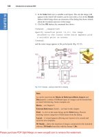
DesignCenter palette: Fig. 1.11 shows the palette showing the
Block drawings of electronics circuit symbols from an AutoCAD
directory DesignCenter from which the drawing file Basic Elec-
tronics has been selected. An electronics symbol drawing can be
dragged from the DesignCenter for inclusion in a drawing under
construction.
Properties palette: Fig. 1.12 shows the Properties palette, also called
from the Standard Annotation toolbar, in which the general and
Introducing AutoCAD 2008 7
Fig. 1.8 Menus and sub-menus
Fig. 1.9 A two-button mouse
Ch01-H8512.qxd 4/4/07 6:31 PM Page 7
geometrical features of a selected polyline are shown. The polyline
can be changed by the entering of new figures in parts of the
palette.
The DASHBOARD palette
Click on Tools in the menu bar and from the drop-down menu
which appears click Dashboard. The DASHBOARD palette appears
(Fig. 1.13). Right-click in the title bar of the palette and a popup
menu appears. Click on Control panels and click against names
which appear in the sub-menu. Parts of the DASHBOARD disappear
leaving only those control panels selected from the popup list.
This can be reduced in size by dragging at corners or edges, or hidden by
clicking on the Auto-hide icon, or moved by dragging on the Move icon.
8 Introduction to AutoCAD 2008
Fig. 1.10 A left-click on the
DesignCenter icon brings the
DesignCenter palette to screen
Fig. 1.11 The DesignCenter
palette
Ch01-H8512.qxd 4/4/07 6:31 PM Page 8
Notes
1. Throughout this book tools will be shown as selected from the
DASHBOARD control panels. It will be seen in Chapter 3 that tools
can be ‘called’ in a variety of ways but, in the main, tools will be
selected from the control panels in the DASHBOARD.
2. For more details about the DASHBOARD, see page 18.
Dialogs
Dialogs are an important feature of AutoCAD 2008. Settings can be made
in many of the dialogs, files can be saved and opened, and changes can be
made to variables.
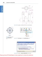
Examples of dialogs are shown in Figs 1.14 and 1.15. The first exam-
ple is taken from the Select File dialog (Fig. 1.14), opened with a click on
Open in the File drop-down menu (Fig. 1.16). The second example
shows part of the Options dialog (Fig. 1.15) in which many settings can
be made to allow operators the choice of their methods of constructing
Introducing AutoCAD 2008 9
Fig. 1.12 The Properties palette
Fig. 1.13 The DASHBOARD
palette
Ch01-H8512.qxd 4/4/07 6:31 PM Page 9
10 Introduction to AutoCAD 2008
Fig. 1.14 The Select File dialog
Fig. 1.15 Part of the Options
dialog
Ch01-H8512.qxd 4/4/07 6:31 PM Page 10
drawings. The Options dialog can be opened with a click on Options
in the right-click menu opened in the command window.
Note the following parts in the dialog many of which are common to
other AutoCAD dialogs:
Title bar: showing the name of the dialog.
Close dialog button: common to other dialogs.
Popup list:a left-click on the arrow to the right of the field brings down a
popup list which lists selections available in the dialog.
Buttons:a click on the Open button brings the selected drawing on
screen. A click on the Cancel button, closes the dialog.
Preview area: available in some dialogs – shows a miniature of the selected
drawing or other features, only part of which is shown in Fig. 1.14.
Note the following in the Options dialog:
Tabs:a click on any of the tabs in the dialog brings a sub-dialog on screen.
Check boxes: a tick appearing in a check box indicates the function
described against the box is on. No tick and the function is off. A click
in a check box toggles between the feature being off or on.
Radio buttons: a black dot in a radio button indicates the feature
described is on. No dot and the feature is off.
Slider: a slider pointer can be dragged to change sizes of the feature con-
trolled by the slider.
Buttons in the status bar
A number of buttons in the status bar can be used for toggling (turning
on/off) various functions when operating within AutoCAD 2008 (Fig. 1.17).
A click on a button turns that function on, if it is off, a click on a button when
it is off turns the function back on. Similar results can be obtained by using
function keys of the computer keyboard (keys F1 to F10).
SNAP: also toggled using the F9 key. When snap on, the cursor under
mouse control can only be moved in jumps from one snap point to
another. See also page 14.
Introducing AutoCAD 2008 11
Fig. 1.16 Opening the Select File
dialog from the File drop-down
menu
Ch01-H8512.qxd 4/4/07 6:31 PM Page 11
GRID: also toggled using the F7 key. When set on, a series of grid points
appears in the drawing area. See also page 14.
ORTHO: also toggled using the F8 key. When on, lines, etc. can only be
drawn vertically or horizontally.
POLAR: also toggled using the F10 key. When set on, a small tip appears
showing the direction and length of lines, etc. in degrees and units.
OSNAP: also toggled using the F3 key. When set on, an osnap icon
appears at the cursor pick box. See also page 45.
OTRACK: when set on, lines, etc. can be drawn at exact coordinate
points and precise angles.
DUCS: Dynamic UCS. Also toggled by the F6 key. Used when construct-
ing 3D solid models.
DYN: Dynamic Input. When set on, the x, y coordinates and prompts
show when the cursor hairs are moved.
LWT: when set on, lineweights show on screen. When set off,
lineweights only show in plotted/printed drawings.
Maximise Viewport: when in Paper Space a button can toggle Model
Space and Paper Space and a new button appears for toggling
between Maximizing and Minimizing the workspace.
Note the square light-blue button at the right-hand end of the status bar –
the Clean Screen button. Left-clickthis button and a screen clear of all but
the menu bar and the command palette appears. When in the Clean
Screen workspace another click on the button and the screen reverts to its
original state.
Note
When constructing drawings in AutoCAD 2008 it is advisable to toggle
between Snap, Ortho, Osnap and the other functions in order to make
constructing easier.
The AutoCAD coordinate system
In the AutoCAD 2D coordinate system, units are measured horizontally in
terms of X and vertically in terms of Y. A 2D point can be determined in
terms of X, Y (in this book referred to as x, y). x,y ϭ 0,0 is the origin of
the system. The coordinate point x,y ϭ 100,50 is 100 units to the right of
the origin and 50 units above the origin. The point x,y ϭϪ100,Ϫ50 is
100 units to the left of the origin and 50 points below the origin. Fig. 1.18
shows some 2D coordinate points in the AutoCAD window.
12 Introduction to AutoCAD 2008
Fig. 1.17 The buttons in the
status bar
Ch01-H8512.qxd 4/4/07 6:31 PM Page 12