Google SketchUp Cookbook phần 5 ppt
Bạn đang xem bản rút gọn của tài liệu. Xem và tải ngay bản đầy đủ của tài liệu tại đây (1.03 MB, 39 trang )
Unsticking Edges
|
139
Because the books themselves are not grouped, other
books will stick to them. In Figure 6-16, the second
vertical stack is moved next to the stack currently on
the bottom shelf, so that the adjacent orange and pink
books share a face.
Figure 6-16
If you try to move the new stack so that the large cyan
book aligns with the front of the shelf, the face and
common edges shared with the orange book move, too
(Figure 6-17).
The solution to this problem is to make each stack of
books into a group. In addition to preventing stickiness,
each book stack will be easy to select, using one click
instead of selection windows that can select more or less
than you need. (You could make the bookcase itself into
a group, too, but that won’t solve the problem of books
sticking to each other.)
Download my 1. Bookcase model (shown previously
in Figure 6-12) from the 3D Warehouse.
Make each stack of books into its own group (Fig-2.
ure 6-18).
Figure 6-17
Figure 6-18
Move one of the vertical stacks to the front-left 3.
corner of the bottom shelf (Figure 6-19).
Figure 6-19
140
|
Chapter 6: Groups: Protect and Defend
Move the stack a bit to the right (Figure 6-20), and 4.
the bookcase remains unchanged.
Figure 6-20
Place the other vertical stack so that the adjacent 5.
orange and pink books share a face (Figure 6-21).
Figure 6-21
This new stack protrudes into the back of the book-6.
case, so it needs to be moved a bit forward. Move
it so that the cyan book aligns with the front of the
bookcase. As shown in Figure 6-22, the two stacks
remain separate; the pink book does not remain
stuck to the orange book.
You could also move the stacks apart; they are not
glued at their common plane.
Figure 6-22
Protecting from Edits
|
141
Place the horizontal stack on the top shelf; align it 7.
at the front corner of the shelf (Figure 6-23).
Figure 6-23
Move the stack up (perhaps to make room for more 8.
books). The bookcase remains unchanged (Figure
6-24).
Figure 6-24
Protecting from Edits6.3
Problem
You have a floor and walls for a room, but when you create new objects in the room, the walls
and floor are changed.
Solution
Protect the room by making it a group. You can still use the faces and edges in the room group
as a basis for new objects.
Discussion
Objects inside a group cannot be changed (unless the group is open for editing). You can still
inference faces, edges, and points of grouped geometry when creating new objects, so you can
draw objects outside or around grouped walls and floors. But any objects created outside the
group will not affect anything inside the group.
142
|
Chapter 6: Groups: Protect and Defend
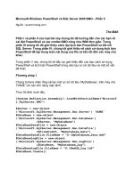
Consider the room shown in Figure 6-25, which has
two walls and the floor displayed. The goal is to add a
bureau in the corner where the rectangle is drawn on
the floor, and to add a clock to the wall where the circle
is drawn.
Figure 6-25
If the room is not grouped, there are three problems you
could encounter:
When you pull out these shapes, the objects that •
are created have the same material as the face from
which they were pulled (Figure 6-26). Obviously,
you could change the materials, but that takes some
extra steps.
Figure 6-26
The • Push/Pull operations affect the back faces of
the walls and floor (Figure 6-27). You could keep
the walls and floor whole by using the Ctrl/Option
key with Push/Pull, but the wall and floor faces
would still be divided by the original clock and
bureau edges.
Figure 6-27
If you select and move the bureau, the walls and •
floor become distorted (Figure 6-28), because two
edges of the bureau are shared with the walls and
floor, and they remain stuck together while moving.
(You should recognize this problem from Recipes
6.1 and 6.2.)
Figure 6-28
Protecting from Edits
|
143
You can solve all three problems by grouping the room.
Start with a box and remove two sides and the top. 1.
Paint the walls and floor.2.
Make the room into a group.3.
Draw a circle on the wall for a clock, and draw a 4.
rectangle on the corner of the floor for the bureau
(Figure 6-29). Even though the referenced faces
and edges are inside a group, you can use them as
a basis for the new objects. The edges of these new
shapes are bold, which means they are not inte-
grated into the walls and floor, and the new faces
are created in the default face color.
Note
The circle and rectangle faces can appear to have distorted, or
shimmering, materials when you orbit around the model. This
is due to SketchUp’s face confusion or Z-fighting. These faces
occupy the same exact planes as other faces, so SketchUp
doesn’t know which material to assign. This is why it looks like
both materials are visible when you orbit around. After you
give either new face some thickness, the material distortion
disappears.
Pull the faces out. As shown in Figure 6-30, the new 5.
objects have the default color, and if you orbit to the
back, you’ll see that the backs of the walls and floor
are not affected.
Move the bureau to another part of the room, and 6.
the walls and floor remain intact (Figure 6-31).
Figure 6-29
Figure 6-30
Figure 6-31
144
|
Chapter 6: Groups: Protect and Defend
Cutting and Slicing6.4
Problem
You want to make slices of a model in order to create floor plans, stripes, or other types of
patterns.
Solution
Make grouped faces to use as the slicing objects, and use the Intersect tool to create the slices.
Discussion
If you read Chapter 3, you’re familiar with the Intersect tool and with various ways that groups
and components can be used as cutting tools. This recipe focuses on using copied groups to
slice objects at set intervals.
The main example demonstrates using slicing groups to create floor plans for a tower. In the
“Other Uses” section, you’ll see how slicing groups can produce linear and rotational stripes.
Start with a tower model like the one in Figure 1.
6-32. You can create your model from scratch, or
download my Tower Floor Plans model from the
3D Warehouse.
Want to Create This Model Yourself?
Create two identical, rectangular towers that have the 1.
same height.
To make the top, horizontal portion, draw a rectangle 2.
at the top of one of the towers and pull it to meet the
other tower.
Erase extra edges.3.
To slope the sides, move the top-right and bottom-left 4.
edges.
To make the first slicing group, switch to Top view 2.
and draw a rectangle in blank space, large enough
to contain the entire tower.
The reason for drawing it in blank space is so that
the rectangle won’t affect the bottom of the tower.
If the rectangle touches any part of the tower, it will
create edges on the tower.
Make the rectangle into a group (Figure 6-33).3.
Figure 6-32
Figure 6-33
Cutting and Slicing
|
145
Move the grouped rectangle so that it encompasses 4.
the bottom of the tower (Figure 6-34).
Figure 6-34
Make several vertical copies of the group, from 5.
bottom to top (Figure 6-35). Erase the groups at the
very bottom and the very top.
To create edges where the groups meet the tower,
you could use the Intersect tool on the tower itself,
which would give you edges for each floor. But
these edges would be visible from the outside of the
tower and would break up the tower walls. To keep
the building exterior clean, with no edges along the
walls, you need to edit the groups instead.
To create one of the floors, open any of the slicing 6.
groups for editing.
Editing these groups is easier when the 7. rest of
model is hidden while editing. So open the Model
Info window (Window→Model Info) to the Compo-
nents page, and select the Hide checkbox for Rest of
Model.
Right-click on the rectangle and choose 8.
Intersect→Intersect with Model.
As you can see in Figure 6-36, the result is edges
on the face where the group meets the walls of the
tower.
Because these edges are along the tower walls, they 9.
would be visible from outside the tower. To create
the floor so that its edges cannot be seen from the
outside, use the Offset tool to offset the new faces
slightly inward (Figure 6-37). After you complete
one offset, you can double-click subsequent offset
faces to offset them by the same distance.
Figure 6-35
Figure 6-36
Figure 6-37
146
|
Chapter 6: Groups: Protect and Defend
Erase everything in the group except for the offset 10.
faces (Figure 6-38).
Figure 6-38
Close the group. As shown in Figure 6-39, you can 11.
see the floor inside the tower by switching to X-Ray
view.
For each remaining group, edit and intersect it, and 12.
then offset the edges to create the floors. Figure
6-40 shows the results in X-Ray view.
The advantage to using groups in the tower is that they
enable you to easily create one offset floor at a time,
without having the rest of the model in view. You could
get the same results without using grouped rectangles,
but it would be much harder to create the offsets and
erase the edges along the walls. If the building were
uniform, with each floor identical, you could have used
components for the slicing planes instead of groups.
Figure 6-39
Figure 6-40
Other Uses
You can use slicing groups to create stripes as well. The
advantage to using groups in these cases is that they are
easy to erase when they are no longer needed.
Striped bowl
The bowl shown in Figure 6-41 was created by using the
Follow Me tool to extrude a tall, oval shape around a
wavy path.
Note
For details on using Follow Me to create round objects, see
Recipe 2.5.
Figure 6-41
Cutting and Slicing
|
147
Create the slicing groups (again, be sure to create the
initial rectangle away from the bowl, group it, and
then move it into place). Make several copies along the
height of the bowl (Figure 6-42).
Figure 6-42
In this example, you do not need to intersect each indi-
vidual group. Instead, right-click on the bowl itself and
choose Intersect→Intersect with Model. This produces
the edges along the bowl, at which point the groups
are no longer needed. You can erase each group with
a simple click; erasing would be much more difficult
if groups were not used. Figure 6-43 shows the results
after painting the stripes.
Figure 6-43
Beach ball
In Recipe 2.6, you can see how to use two circles and
the Follow Me tool to make a sphere. In this example,
after the sphere is created, the larger of the two circles is
then made into a group and rotate-copied all around the
sphere (Figure 6-44). To make copying easier, it is help-
ful to add a center point to one of the circles and switch
to Wireframe view when copying.
Figure 6-44
Run Intersect on the sphere and erase each group to
produce the beach ball shown in Figure 6-45.
Figure 6-45
148
|
Chapter 6: Groups: Protect and Defend
Two-Sided Coloring6.5
Problem
You want to paint both sides of a set of faces.
Solution
Make the faces into a group. When you paint a group, that material or color is applied to all
sides of all faces that are not already assigned a material.
Discussion
When you paint a face, only the side you click gets the material. (The exception to this is when
you paint with a translucent material, which is applied to both sides of a face.) Even when you
use the Shift or Ctrl/Option key to paint multiple faces, either all front faces or all back faces are
painted, but not both sides. This is by design; “real-world” faces indeed have two sides. But in
some cases, you might want to paint both sides of a face, and you can use groups for this.
Note
Using the Shift and Ctrl/Option keys to paint multiple faces is
discussed in Recipe 8.4.
The main example shows how to paint both faces of
walls of a house. In “Other Uses,” you’ll see how two-
sided painting helps while making cut-throughs.
Consider the model of a house with a painted roof
shown in Figure 6-46. All faces other than the tops of
the roof have the default front and back colors.
Figure 6-46
If a wood material is activated, and is applied to any
front face while the Shift key is pressed, all front faces
are painted with wood (Figure 6-47). The back faces
still have the default back color.
Note
If you want to paint both sides of a set of faces without using
groups, you can use the Reverse Faces option. Select the faces
to paint, and paint all of the sides that are showing. Leave
the faces selected, right-click on one of them, and choose
Reverse Faces. This switches the front and back sides of the
face, so you can apply the same material to the sides that are
now showing.
Figure 6-47
Two-Sided Coloring
|
149
To paint the back faces to look like Figure 6-48, you
must Shift-click one of the inner walls.
If you want to paint both sides of faces at once, the solu-
tion is to make a group that includes the faces you want
to paint.
Create a house like the one in Figure 6-46, whose 1.
walls have the default colors and a painted roof. Cut
holes for windows so you can see the inside walls.
Make the entire house a group.2.
Activate a material and click the group. (Do not 3.
open the group for editing; simply click the group
while it is closed.) As shown in Figure 6-48, both
sides of the default-painted walls get the new mate-
rial. The only faces not painted are those at the top
of the roof, because they already had an assigned
material. (The underside of the roof faces do get the
new material, assuming you didn’t paint those faces
before you made the group.)
Other Uses
Recipe 3.3 demonstrated how to use groups or com-
ponents to cut through objects. The basic steps are as
follows:
Group the cutting object.•
Move the cutting group into place.•
Use the Intersect tool to get intersection edges.•
Explode the group.•
Trim extra edges.•
If you want the cut faces of the trimmed object to have
the same color as the cutting object itself, both sides of
the cutting object’s faces should be painted. (You could
just paint the back faces, but that’s rather difficult when
an object is closed.)
Consider a sphere like the one in Figure 6-49 that needs
a rectangular hole cut through it. The cutting object is a
long box that will pass through the sphere when moved
into place. The box is not a group (yet).
To paint the entire box, pick a color (green, in this case),
press and hold Shift, and click any face of the box. As
you can see in Figure 6-50, the outside faces become
green. But the inside faces of the box are not painted.
After painting, move the cutting object into place.
Figure 6-48
Figure 6-49
Figure 6-50
150
|
Chapter 6: Groups: Protect and Defend
The result after Intersect and trimming is shown in
Figure 6-51. The cutout walls have the default color, be-
cause the inside faces of the cutting box had the default
color.
Figure 6-51
Go back to the beginning. If the cutout face color is to
match the color of the cutting object, the cutting object
should be a group. Then paint the group (Figure 6-52).
Figure 6-52
Figure 6-53 shows the result after you move the group
into place, intersect, explode, and trim: the cutout walls
have the cutout color. This is because both front and
back faces of the cutting object were painted as a group.
Figure 6-53
Locking a Group
|
151
Locking a Group6.6
Problem
You want to prevent a group from being moved, erased, or edited.
Solution
Lock the group.
Discussion
If there is a portion of your model that you know will not change, or you want to prevent ob-
jects from accidental changes or deletion, the solution is to make these objects into a group (or
a component) and lock it. Lock (and Unlock) are available on a group’s pop-up menu, as well as
on the pop-up menu of a group in the Outliner.
Figure 6-54 shows a piece of terrain upon which a
model is to be built. For this example, you know that
no parts of the terrain, including the stream, hills, and
trees, will change, and you want to make sure these
objects will not inadvertently be moved or edited by you
or anyone else who works on the file.
Figure 6-54
The solution is to make all of these objects into a locked
group. Create the group and then right-click on the
group and choose Lock. The bounding box and edges of
a locked group are displayed in red (Figure 6-55).
Figure 6-55
If you open the Outliner (Window→Outliner), the
group’s symbol has a lock symbol, as indicated in Figure
6-56.
Note
When you use the Get Current View tool to import terrain
from Google Earth into SketchUp, the terrain is imported into
SketchUp as a locked group. This is to prevent the terrain from
being moved or edited. For more information, see Recipe 13.9.
Figure 6-56
An essential feature of SketchUp, components can
greatly increase your modeling efficiency as well as
keep your file size as trim as possible. Components
are geometrically similar to groups in that they are
“sealed” and protected from other geometry and are
selectable as a single object. Because components of-
fer additional features, however, you can do much
more with components than with groups.
If you’re unsure about when to use a component
versus a group, the general rule is that groups are
mainly used for keeping objects separate from
other objects, and they generally do not repeat.
Components are the better choice for the follow-
ing objects:
• Objects that will be repeated at least once in
the model
• Objects that will be saved into their own file
Objects that have • specific alignment or inser-
tion properties
Objects that will • cut faces, such as windows
and doors
• 2D objects that are to always face the camera
CHAPTER 7
Components: Efficiency in Repetition
The best-known feature of components is that
they can be used for repeated objects; if you edit
one, all copies of that component change as well.
Components can also cut faces, align to specific
faces, and always face the camera. Using repeated
components, rather than copying faces and
edges, can greatly decrease your file size, because
SketchUp has to recognize only one set of geo-
metric objects, and needs only location and size
information for each component instance.
This chapter delves into the many uses and fea-
tures of components, which no serious SketchUp
modeler can live without.
154
|
Chapter 7: Components: Efficiency in Repetition
Creating a Component7.1
Problem
You want to combine several objects into a component.
Solution
Use the Create Component window.
Discussion
To create a component from objects in the model, first select the objects to include in the com-
ponent. You can then do one of the following:
Choose Edit→• Make Component from the main menu.
Right-click on one of the selected objects and choose Make Component from the pop-up •
menu.
Click the Make Component icon.•
This opens the Create Component window.
Note
Although a component usually consists of more
than one object, you can make a component
from a single object. If only one face or edge is
selected, Make Component does not appear
in the pop-up menu, but you can choose
Edit→Make Component from the main menu,
or use the Make Component icon. If you want
to make a single face into a component, you
can activate Select and double-click the face.
Because this selects both the face and its edges
(more than one object is selected), Make Com-
ponent appears in the pop-up menu.
In the Create Component window (Figure 7-1), you can
assign a name for the component or accept the default
name. The description is optional.
Here is a quick description of the other options in the
Create Component window:
• Alignment options are used for objects that are
meant to align to all or specific faces (Recipe 7.10).
The “• Cut opening” checkbox is selected for objects
such as windows, which cut the faces within which
they are inserted (Recipe 7.12).
Use “• Always face camera” for 2D “cutout” compo-
nents such as people, animals, trees, and shrubs,
which always face the camera no matter the model
orientation, giving the illusion of 3D volume (see
Recipe 9.4). The “Shadows face sun” option is
relevant for these types of components as well, to
correct “skinny” shadows when the component’s
edges are along the sun’s orientation.
• Set Component Axes is used to define the compo-
nent’s insertion point and orientation.
If the “• Replace selection with component” checkbox
is selected, the selected objects will be replaced with
the new component. Always look at this option
when creating a component, because this option is
not always selected by default.
Figure 7-1
Using the Components Window
|
155
Using the Components Window7.2
Problem
You want to find, view, and insert components.
Solution
Use the Components window.
Discussion
From the Components window (choose Window→Components), you can view and manipulate
the components in your model, as well as find external models to use as components.
SketchUp comes with a few components installed,
which you can access through the Components window
(Figure 7-2). Users of the free version see only a Com-
ponents Sampler folder in the window, and Pro users
also have a folder with training examples for dynamic
components (Chapter 14). The models in these fold-
ers are stored on your hard drive, where SketchUp is
installed. (If you don’t see these folders in the Compo-
nents window, click the Select tab, click the arrow next
to the house icon, and choose Components from the
resulting drop-down menu.)
Note
The Components Sampler folder contains many dynamic
components, which are identifiable by the green and white
icon in the thumbnail. Free users can insert and interact with
dynamic components, just not create their own. This folder
also contains some “regular” (nondynamic) components.
This chapter focuses only on “regular” components; dynamic
components are described in Chapter 14.
Additional sampler components by Google are stored in
the 3D Warehouse. To access them, make sure the Select
tab is active and then click the arrow next to the house
icon to open the drop-down menu (Figure 7-3). Choos-
ing one of the links—Architecture, Landscape, Con-
struction, or People—takes you directly to the selected
collections on the 3D Warehouse website. To insert a
3D Warehouse model directly into your model, click
its thumbnail and click again in the model. Clicking
on a model’s name or a collection’s name will open that
component’s page in the 3D Warehouse, where there are
options to open or save the model.
Figure 7-2
Figure 7-3
156
|
Chapter 7: Components: Efficiency in Repetition
Note
For more details on finding models in the 3D Warehouse, see
Recipe 13.1.
When you insert a component into your model, Sketch-
Up automatically includes it in your In Model folder. To
open this folder, click the Select tab’s house icon (Figure
7-4).
To view or edit component properties, highlight the
component in the In Model folder and click the Edit
tab. (You can also right-click on a component thumb-
nail in the Components window and choose Properties
from the pop-up menu to open the Edit tab.) From the
Edit tab, you can change any of the properties (align-
ment, openings, and so on) that were set when the
component was originally created.
The Statistics tab shows how many edges, faces, im-
ages, and the like are included in the component.
This is a great way to see how complex, and therefore
resource-heavy, a component is. The Statistics tab also
lists Component Instances, which refers to the number
of nested components within the selected component,
not the number of components found in the model. The
number of component instances in the model is listed at
the bottom of the Statistics list (in Windows), or can be
found in a component’s Entity Info window.
Figure 7-4
Note
If you delete all instances of a component
from your model, the component will still ap-
pear in the In Model folder. This is intentional,
with the thought that you might change your
mind and want to use the component after all.
There is a Purge Unused option that will clean
out your Components window of unused
components. Purging components can greatly
speed up a heavy model.
Inserting a Component
|
157
Inserting a Component7.3
Problem
You want to insert a SketchUp model into your model as a component.
Solution
Use the Components window, or drag and drop from your file browser, or choose File→Import
from the main menu.
Discussion
Components that you do not create yourself from scratch within your current model come
from external SketchUp files. There are a few ways to insert models from outside your file:
As discussed in Recipe 7.2, you can find models in the • Components Sampler folder and in
sampler collections in the 3D Warehouse. To insert one of these models, click the model
thumbnail in the Components window, and click again to place the component in your
model.
If the SketchUp model you want to use as a component is on your hard drive, you can im-•
port it. From the main SketchUp menu, choose File→Import. In the Import window, make
sure you are searching for SketchUp files (as opposed to graphic files), and browse to the
file you want to insert as a component.
If the model file is on your hard drive, you can also use your computer’s file browser to in-•
sert the model. Simply click and drag the filename and drop it directly into the SketchUp
window.
158
|
Chapter 7: Components: Efficiency in Repetition
Editing or Exploding a Component7.4
Problem
You need to make changes to a component, or explode it so that it is no longer a component.
Solution
To change a component, you open it for editing, make changes, and close the component. To
explode a component, right-click on it and choose Explode.
Discussion
Editing and exploding a component is done the same way as for groups, which is covered in
Chapter 6. The difference with components is that when you edit one, all identical components
automatically get the same changes.
Exploding a single component, however, does not affect other components. If you want to ex-
plode more than one component, select them in advance. When you choose Explode from the
pop-up menu, all selected components will be exploded.
Note
If you work with layers, keep in mind this strange behavior of exploded components: If the original objects composing
the component are on Layer0 (SketchUp’s default layer), and the component is on a different layer, the original objects
will take on the new layer after the component is exploded. This does not happen if the original objects are on layers
other than Layer0.
Renaming a Component
|
159
Renaming a Component7.5
Problem
You want to rename a component.
Solution
Use the Definition Name field of the Components window or the Entity Info window.
Discussion
When you insert a component from the 3D Warehouse or import a SketchUp model as a
component, SketchUp inserts the component by using a name identical to the filename of the
inserted model. You might want to change this name. You might also want to change the name
of a component you created yourself, even though you assigned it a name upon creation. There
are two ways to change a component’s name: directly in the Components window or in the
Entity Info window.
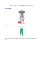
Figure 7-5 shows a room with three components: a sofa,
coffee table, and bookcase. When you examine these in
the Components window’s In Model folder (opened by
clicking the house icon as indicated in Figure 7-6), you
see that their names (listed in bold next to each com-
ponent thumbnail) were taken from the original model
files and are a bit awkward.
Note
Component names appear in Detail view but not in Thumb-
nails view. The view can be set by clicking the View Options
icon, located to the left of the house icon in the Components
window.
Figure 7-5
Figure 7-6
160
|
Chapter 7: Components: Efficiency in Repetition
One way to rename a component is directly in the
Components window. Select a component, such as the
bookcase, and enter a new name in the top field (Figure
7-7). Keep in mind that if you select a component to
rename this way, SketchUp thinks you want to insert the
component, and attaches an instance of the component
to your cursor when you move back to the model. You
can end this insertion mode by pressing the Esc key.
Figure 7-7
The second way to rename a component is to use the
Entity Info window. If this window is not already open,
right-click on the component to rename, and choose
Entity Info from the pop-up menu. If the Entity Info
window is already open, just select the component you
want to rename. Rename the component by entering the
new name in the Definition Name field (Figure 7-8).
Figure 7-8
Saving a Component in Its Own File7.6
Problem
You have objects in your model that you want to use in another model.
Solution
Make the objects into a component, and use the Save As option in the pop-up menu.
Discussion
If you want your entire model (which has not been made into one component) to be used later
as a component, the solution is simply to save the file. When you are ready to import the model
into a new file, you then choose File→Import, and find the saved model. It will be inserted as a
component, surrounded by a bounding box.
But what if you want to save only selected objects of the model for later use as a component?
Accessing Local Components
|
161
Figure 7-9 shows a model of a room containing a sofa,
bookcase, and coffee table. For this example, assume
that all of these objects were built from scratch within
SketchUp, not imported as components from external
files. The goal is to save the coffee table into its own file,
so that it can be imported into other models. Make the
coffee table into a component (Recipe 7.1); right-click
on the component, either in the model itself or in the
Components window; and choose Save As from the
pop-up menu. The default filename is the name you
assigned to the component when it was created; you can
change it if you want. After the file is saved, it can be
imported as a component in future files.
What you are saving into their own file are the objects
inside the component and not an instance of the com-
ponent. The component’s axes become the model axes
for the saved objects.
Keep in mind that many models in the 3D Warehouse
were not saved this way; they were first made into com-
ponents within their original file and then uploaded
to the 3D Warehouse. A component like this will have
a double bounding box when you insert it into your
model. Some 3D Warehouse models also have issues
with axes and insertion properties, which are explained
in Recipe 7.10.
Figure 7-9
Accessing Local Components7.7
Problem
You have folders of SketchUp model files on your hard drive and want to be able to access these
folders from the Components window.
Solution
Add the folders to your Components window’s Favorites.
Discussion
Google makes storing your models and collections easy in the 3D Warehouse, by providing
unlimited space and access, as well as providing security and privacy options. But some users
prefer to keep their component models local, stored either on their hard drive or on an internal
company network.
162
|
Chapter 7: Components: Efficiency in Repetition
Note
For details on storing your own models and collections in the
3D Warehouse, see Recipes 13.3 through 13.7.
The first step is to organize your models on your hard
drive. Figure 7-10 shows the folder My SketchUp Com-
ponents with three subfolders for Appliances, Cabin-
etry, and Furniture. The Furniture folder itself has three
subfolders. These folders contain SketchUp models.
Figure 7-10
To open My SketchUp Components from the Com-
ponents window, click the Details arrow indicated in
Figure 7-11. From the pop-up menu that opens, choose
“Open or create a local collection.” Browse to My
SketchUp Components and click OK. This folder is now
displayed in the Components window, and you can see
its subfolders (Figure 7-12).
To be able to access this folder without having to browse
for the folder each time, click the Details arrow again
and choose “Add to favorites.” My SketchUp Com-
ponents will now appear in the drop-down menu of
component folders.
To remove a folder from Favorites, open the folder and
use the “Remove from favorites” option from the De-
tails arrow pop-up menu.
Figure 7-11
Figure 7-12
Painting Components
|
163
Painting Components7.8
Problem
You want to paint components different materials or colors.
Solution
Use the default material for faces you want to paint. When you apply paint to a closed compo-
nent (a component not open for editing), all faces that have the default color will get the new
material.
Discussion
If repeating objects are identical except for their colors, there is no need to model each object
separately. The efficient solution is to make one component in which you leave the default
material for those faces you plan to paint later. Faces that already have a material assigned will
keep that material when the component is painted; only faces with the default material will be
painted when this technique is used. Because the face is painted from “without,” not during
component editing, the paint applies only to the individual component you are painting.
In the main example, you will create several identical houses that have different materials for
the walls, but the same materials for the roofs, doors, and windows. In the “Other Uses” section,
you’ll see how this technique can be applied to make colored racecars, and different gemstones
in identical settings.
Create a simple house with one window and one 1.
door (Figure 7-13). Paint the roof, door, and win-
dow, but leave the walls in the default color.
Make the entire house into a component (Recipe 2.
7.1).
Make several copies of the house component.3.
To paint each house, simply activate a material and 4.
click the house component. All inside and outside
walls are painted, but the front faces of the roof,
door, and window keep the materials they were
originally assigned (Figure 7-14).
To change the colors on the door, roof, or window,
you would need to edit the component (Recipe 7.4).
Note
Painting a component or group this way is a great way to
quickly paint both sides of a set of faces. For details, see
Recipe 6.5.
Figure 7-13
Figure 7-14