Báo cáo khoa học: "The GLAaS algorithm for portal dosimetry and quality assurance of RapidArc, an intensity modulated rotational therapy" pdf
Bạn đang xem bản rút gọn của tài liệu. Xem và tải ngay bản đầy đủ của tài liệu tại đây (838.79 KB, 10 trang )
BioMed Central
Page 1 of 10
(page number not for citation purposes)
Radiation Oncology
Open Access
Methodology
The GLAaS algorithm for portal dosimetry and quality assurance of
RapidArc, an intensity modulated rotational therapy
Giorgia Nicolini
1
, Eugenio Vanetti
1
, Alessandro Clivio
1,3
, Antonella Fogliata
1
,
Stine Korreman
4
, Jiri Bocanek
5
and Luca Cozzi*
1,2
Address:
1
Oncology Institute of Southern Switzerland, Medical Physics Unit, Bellinzona, Switzerland,
2
University of Lausanne, Faculty of
Medicine, Lausanne, Switzerland,
3
University of Milan, Medical Physics Specialisation School, Milan, Italy,
4
Rigshospitalet, Radiation Oncology
Dept, Copenhagen, Denmark and
5
Varian Medical Systems Int. AG, Zug, Switzerland
Email: Giorgia Nicolini - ; Eugenio Vanetti - ;
Alessandro Clivio - ; Antonella Fogliata - ; Stine Korreman - ;
Jiri Bocanek - ; Luca Cozzi* -
* Corresponding author
Abstract
Background: To expand and test the dosimetric procedure, known as GLAaS, for amorphous silicon
detectors to the RapidArc intensity modulated arc delivery with Varian infrastructures and to test the
RapidArc dosimetric reliability between calculation and delivery.
Methods: The GLAaS algorithm was applied and tested on a set of RapidArc fields at both low (6 MV)
and high (18 MV) beam energies with a PV-aS1000 detector. Pilot tests for short arcs were performed on
a 6 MV beam associated to a PV-aS500. RapidArc is a novel planning and delivery method in the category
of intensity modulated arc therapies aiming to deliver highly modulated plans with variable MLC shapes,
dose rate and gantry speed during rotation. Tests were repeated for entire (360 degrees) gantry rotations
on composite dose plans and for short partial arcs (of ~6 or 12 degrees) to assess GLAaS and RapidArc
mutual relationships on global and fine delivery scales. The gamma index concept of Low and the
Modulation Index concept of Webb were applied to compare quantitatively TPS dose matrices and dose
converted PV images.
Results: The Gamma Agreement Index computed for a Distance to Agreement of 3 mm and a Dose
Difference (ΔD) of 3% was, as mean ± 1 SD, 96.7 ± 1.2% at 6 MV and 94.9 ± 1.3% at 18 MV, over the field
area. These findings deteriorated slightly is ΔD was reduced to 2% (93.4 ± 3.2% and 90.1 ± 3.1%,
respectively) and improved with ΔD = 4% (98.3 ± 0.8% and 97.3 ± 0.9%, respectively). For all tests a grid
of 1 mm and the AAA photon dose calculation algorithm were applied. The spatial resolution of the PV-
aS1000 is 0.392 mm/pxl. The Modulation Index for calculations resulted 17.0 ± 3.2 at 6 MV and 15.3 ± 2.7
at 18 MV while the corresponding data for measurements were: 18.5 ± 3.7 and 17.5 ± 3.7. Partial arcs
findings were (for ΔD = 3%): GAI = 96.7 ± 0.9% for 6° rotations and 98.0 ± 1.1% for 12° rotations.
Conclusion: The GLAaS method can be considered as a valid Quality Assurance tool for the verification
of RapidArc fields. The two implementations (composite rotation or short arcs) allow the verification of
either the entire delivery or of short partial segments to possibly identify local discrepancies between
delivery and calculations. RapidArc, according to the findings, appears to be a safe delivery method in terms
of dosimetric accuracy allowing its clinical application.
Published: 9 September 2008
Radiation Oncology 2008, 3:24 doi:10.1186/1748-717X-3-24
Received: 21 July 2008
Accepted: 9 September 2008
This article is available from: />© 2008 Nicolini et al; licensee BioMed Central Ltd.
This is an Open Access article distributed under the terms of the Creative Commons Attribution License ( />),
which permits unrestricted use, distribution, and reproduction in any medium, provided the original work is properly cited.
Radiation Oncology 2008, 3:24 />Page 2 of 10
(page number not for citation purposes)
1. Background
Electronic portal imagers based on amorphous silicon flat
panels are quite largely utilized for dosimetric purposes
[1-7], mainly for pre-treatment IMRT verification beams,
allowing time sparing and good accuracy. Performances
and characteristics of the amorphous silicon detectors
have been investigated. In particular, solid results exist on
linear response in dose, non reproducibility of the off-axis
ratio, different response at different field sizes and differ-
ent energies and spectra, etc. In general, to manage unde-
sired aspects of these detectors, special algorithms have
been developed and adopted aiming to convert raw
images into dose readings.
Our group developed one similar algorithm, named
GLAaS [8,9] to convert PV-aS500 (and PV-aS1000) images
into dose matrices. The starting point for GLAaS develop-
ment was pre-treatment IMRT verifications and as such
GLAaS is routinely used and results were reported. GLAaS
is based on the application at pixel level of specific dose
response parameters distinguishing between primary and
transmitted radiation (from MLC or main jaws). In addi-
tion, GLAaS accounts for perturbations (e.g. the backscat-
tering from the support arm or the beam over-flattening
induced by the detector calibration for imaging) with
some specific correction factors. GLAaS was recently fur-
ther developed [10] to be used for dosimetric Quality
Assurance of linear accelerators (e.g. to measure beam
profiles for open and wedged, symmetric and asymmetric
fields or to measure output and wedge factors for con-
stancy checks).
The present report describes a new application of GLAaS
for dosimetric verification of intensity modulated arcs.
Recently, a novel technology called RapidArc was intro-
duced on Varian linear accelerators. RapidArc belongs to
the class of intensity modulated arc therapies [11-15].
This new delivery modality created the need of developing
appropriate approaches to machine and pre-treatment
verification processes. In literature so far, few publications
addressed the usage of two-dimensional arrays to verify
(modulated) arc fields. The usage of a 2D ion chamber
array with a phantom with an octagonal shape was
described in [16]. Other detectors have been used and
tested in the framework of the RapidArc development
teams and provided excellent results with the possibility
to develop different verification strategies. In general,
using external devices, particular attention shall be put to
spatial resolution (some detectors have resolution coarser
than 5 mm) and/or the usage of complementary phan-
toms. GLAaS constitutes an alternative to these
approaches. It has some potential factors of interest being
based on a detector (the PV-aS1000) available on Rapi-
dArc machines; it does not require any phantom for its
application and it operates converting images into abso-
lute dose matrices.
A possible limitation of GLAaS that has to be anticipated.
Given the mechanical mounting of the detector, integral
with the gantry, the arc verification is performed collaps-
ing the entire rotation onto a single verification plane, cre-
ating a sort of composite dosimetric measurement. This
feature could eventually mask the, unlikely, event of
destructive interference of independent delivery (or calcu-
lation) errors. To overcome this feature, a pilot study is
described in this report aiming to use GLAaS in a sort of
fine-angular resolution mode by means of consecutive
acquisition of short arc of few degrees in independent
shots to be individually analysed in sequence.
2. Methods
RapidArc technique
RapidArc is a novel planning and delivery technique for
volumetric delivery of intensity modulated arcs, based on
the concept as published by K. Otto [17]. It consists on a
single arc where MLC (max 5 mm/degree and 2.5 cm/s),
dose rate (max 600 MU/min), and gantry speed (max 72
s/turn, i.e. ~5 degrees/s) are optimized simultaneously to
achieve the desired degree of modulation. At planning
level, RapidArc consists of optimizing a dose distribution
from dose-volume objectives including in the optimiza-
tion the main characteristics of the linac head and the
MLC (e.g. speed, transmission, rounded leaf tip and
tongue and groove design). The entire gantry rotation is
described in the optimization process by a sequence of
177 control points, CP, (one CP every roughly 2° of rota-
tion). The final dose calculation is performed in Eclipse by
means of the AAA algorithm.
One key point of RapidArc planning and delivery is the
usage of collimator angles different from zero, typically in
the range of 35–45 degrees. A non zero collimator angle
implies that the tongue and groove effect, minimised by
the optimizer but not completely avoided, is smeared out
into non coplanar trajectories rather then being piled up
in ''rings" orthogonal to the patients axis as if collimator
would be set to zero.
The software version of both optimizer and dose calcula-
tion is a pre-clinical release of Eclipse 8.2.16. At delivery
level, RapidArc plans are transferred by DICOM-RT com-
munication to the 4D treatment console of the Varian
linacs. Here, the actual treatment parameters are deter-
mined and transferred to the various system controllers.
Particularly, the MLC controllers verifiy every 50 msec the
position of the leaves with respect to expected, previous
and following positions as well as the agreement of deliv-
ered dose. The linac controllers check, with the same fre-
quency and logic, the angular position of the gantry and
Radiation Oncology 2008, 3:24 />Page 3 of 10
(page number not for citation purposes)
the dose rate. Whatever discrepancy should be detected by
the controllers would generate immediate beam off inter-
lock and the delivery would be interrupted.
GLAaS algorithm
The GLAaS algorithm [8,9] has been used to convert raw
images acquired with the portal imager into dose matrices
at the depth of the maximum dose d
max
. No phantom is
used, and radiation field impinges directly onto the detec-
tor. This algorithm was originally developed for IMRT pre-
treatment verification, and here slightly adapted for Rapi-
dArc testing. A brief description of the algorithm follows.
For a given beam, the response of the amorphous silicon
detectors is linear (D(Gy) = m*R+q). IMRT and RapidArc
fields are, however, changing continuously during deliv-
ery. GLAaS accounts for those changes in time and posi-
tion, using different m and q values, and differentiating
between primary and transmitted (below the MLC) radia-
tion, on a pixel by pixel basis.
The total dose d
i
in the i-th pixel, over the entire field deliv-
ery is:
where: m and q are the slope and the intercept for a field
of size EwwF (Equivalent window width Field), r is the
reading attributed to the primary radiation for the seg-
ment/control point s, and R is the total PV reading; sub-
scripts pr refer to primary, tr to transmitted radiation. The
field is considered as a sum of N segments or control
points. In the case of single static field or RapidArc, the key
elements for GLAaS are the same: knowledge of the MLC
shape and of the dose progress at any instant of the deliv-
ery. This information is fully stored in the DICOM-RT
plans from the treatment planning system. In addition,
RapidArc is characterised by variable dose rate during
delivery. It was proven in [10] that the detector response
is independent on the dose rate; in this view the same cal-
ibration parameters set can be used for the whole field,
acquired at any (variable) dose rate.
The parameter values computed during the configuration
of the GLAaS to analytically obtain the slopes come from
the following empirical algorithm:
OF(EwwF) = [x + d·1n(EwwF)]
-1
(2)
where EwwF is the equivalent field size of each segment
m
pr
(OF) = a·OF + b (3)
where m
pr
is the slope for primary radiation, and OF is the
PV measured output factor as per equation (2).
For transmitted radiation the following relationship is
used:
m
tr
= k·m
pr
(4)
GLAaS configuration consists in the determination of a set
of empirical parameters: a, b, c, d, k, q
pr
and q
tr
.
GLAaS has been configured to convert images acquired
without any buildup on the PV cassette into dose at the
depth of maximum dose d
max
(1.5 cm and 3 cm for 6 and
18 MV respectively), at the source-detector distance SDD
= 100 cm.
The GLAaS algorithm was already tested [10] for verifica-
tion of fields with high doses, needed when RapidArc
fields are concerned, because the full dose is delivered in
only one field. This is guaranteed by the way the PV elec-
tronics works, averaging the reading per each pixel over a
number of frames, and recording the reading values and
the number of acquisition frames.
The equipment
To test the new RapidArc approach with GLAaS, a treat-
ment unit installed at Rigshospitalet in Copenhagen has
been used. It is a Clinac 2100iX, equipped with a Millen-
nium multileaf collimator MLC-120, two photon energies
of 6 and 18 MV, Portal Vision PV-aS1000 with full resolu-
tion (0.392 mm/pxl) and with Exact-arm support. The
system allowed RapidArc delivery through a preclinical
software release (vers. 8.2.13) that was installed during
the month of February 2008 to perform delivery investiga-
tions.
The relevant acquisition parameters were: Acquisition
Technique = Integrated Image, Readout = Sync-Integrated.
The pilot study on short arcs was instead performed on a
6 MV beam from a Clinac 6 EX equipped with a PV-aS500
installed at the Oncology Institute of Southern Switzer-
land. This was necessary since the linac in Copenhagen
was not further available for tests. Tests of short arcs were
therefore performed on a simplified RapidArc model
keeping both the dose rate and the gantry speed constant.
One preliminary test that was performed aimed to deter-
mine the eventual apparent PV displacement during gan-
try rotation. This could be to a true support arm
mechanical instability or to gantry sag. The test was
exploited measuring during entire arcs of 360°, clockwise
and counterclockwise, 'cine mode', i.e. with a sequence of
240 images acquired during the arc, a small field of 0.4 ×
0.4 cm
2
. The centres of mass of all images were recorded,
d d d m EwwF r q m R
ipritri prs isprs
s
N
tr i
=+= ⋅+
⎛
⎝
⎜
⎜
⎞
⎠
⎟
⎟
+⋅−
=
∑
,, , , ,
()
1
rrq
is
s
N
tr,
=
∑
⎛
⎝
⎜
⎜
⎞
⎠
⎟
⎟
+
⎛
⎝
⎜
⎜
⎞
⎠
⎟
⎟
1
(1)
Radiation Oncology 2008, 3:24 />Page 4 of 10
(page number not for citation purposes)
and differences with respect to the gantry at 180° (the
starting position) were analysed in x and y directions and
for both rotation directions.
GLAaS applied to RapidArc plans
Seven 'clinical' deliveries, i.e. from true RapidArc plans
optimized for test patients were selected from various
tumour sites (brain, head and neck, thorax, and pelvis).
Different dose prescriptions were applied (from 1.2 to 2.5
Gy/fraction, some including Simultaneous Integrated
Boost). Cases were selected to guarantee a variety of PTV
volumes (ranging from 110 to 1060 cm
3
). This wide vari-
ability was chosen to asses the GLAaS performances on
various RapidArc plan possibilities. Plans were delivered
for both 6 and 18 MV beams. MLC, dose rate and gantry
rotation were operated during the delivery as required by
the clinical plan generating a composite dose image on
the detector that rotates integral with the gantry.
Dose calculations for GLAaS comparison were obtained
from Eclipse. For each RapidArc plan, a "verification plan"
was generated on a water phantom, using the original
parameters (MLC and dose rate). This verification plan
was then "collapsed" on an infinitesimal gantry rotation,
generating a dose distribution of the whole arc on a single
plane, orthogonal to the beam central axis as the detector.
The calculated dose matrix therefore, as the measurement,
integrated the dose contributions delivered at various
angular positions into one single plane. The dose calcula-
tions in the phantom were based on the same algorithm
implemented for RapidArc plans. Every control point was
individually calculated and accumulated, computing the
dose distribution for each CP separately. This allowed to
build a verification plan equivalent to the actual patient
plan. In this study, dose distributions were exported from
Eclipse at d
max
and isocentre distance (given the SDD =
100 cm). Dose calculation grid of verification plans was
set to 1 mm, being the minimum allowed with AAA dose
calculation.
Measured matrices at d
max
converted into dose through
GLAaS were compared to the corresponding computed
doses. Evaluation was performed via the gamma index
[18] on the field area defined by the jaw setting. The eval-
uation criteria were chosen as follows: DTA (distance to
agreement) of 3 mm and ΔD (dose difference) of 2, 3 and
4%. ΔD was defined respect to the significant maximum
dose of the field. This was defined as [8] the maximum
dose value in the distribution of measured dose in the
field after cutting the highest 5% dose tail in the histo-
gram. The Gamma Agreement Index (GAI), defined as the
percentage of points inside the field passing the gamma
evaluation criteria, was computed for each case, and then
averaged over all the cases.
To further analyse their agreement, the Modulation Index
MI [19,20] was computed for both measured and calcu-
lated dose matrices for each field. As known, this parame-
ter is a measure of the degree of modulation:
Where Z(f) is the spectrum of the modulation pattern in
the field and the integration limit F was set to 1, as
described in [20]. The application of the MI on the dose
matrices instead of the fluence maps, allows a more direct
evaluation of the 2D dose maps to appreciate e.g. eventual
dependencies on the dose calculation grid. In this respect,
a comparison of the MI for measured and calculated doses
results in an appreciation of the relative compatibility
between calculation grid and detector resolution.
Partial arcs
A pilot study was performed to assess the GLAaS capabil-
ity to detect fine and local features of RapidArc dose calcu-
lation with respect to delivery. This was performed
computing and measuring, at various positions during the
arc rotation, some short consecutive partial arcs. For two
of the seven plans, three subsequent sub-arcs of ~6°
(178.0–171.8°, 171.8–165.7°, 165.7–159.6°) and of
~12° (178–165.7°, 165.7–153.4°, 153.4–141.2°) were
analysed. In these cases, interrupted plans were generated
in Eclipse selecting the starting and ending control points
(4 CP corresponding to 3 intervals for the 6° sub-arcs, 7
CP corresponding to 6 intervals for the 12° sub-arcs). Ver-
ification plans were computed with the same algorithm
used for the entire arc plan. Interrupted plans were used
also to acquire images. These tests were performed with
fixed dose rate and fixed gantry speed on the 6 MV beam
of the IOSI linac.
Analysis with the gamma evaluation was performed on
the minimum rectangular field area that includes the sub-
arc (instead of the jaws defined field) in order to have a
fair comparison between full arc and partial arc. From
gamma evaluation analysis the GAI were recorded, with
the criteria of DTA = 3 mm and ΔD = 3%.
For this pilot study, the short term stability of repeated
deliveries was tested through three consecutive measure-
ments of each sub-arc.
3. Results
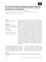
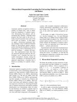
The results of the assessment of the apparent PV support
arm movement are reported in figure 1 where the dis-
placement of the center of mass of the small field is plot-
ted as a function of the gantry position. Blue and light
blue lines, that refer to the displacement in the transversal
MI F Z f df
F
() ()=
∫
0
Radiation Oncology 2008, 3:24 />Page 5 of 10
(page number not for citation purposes)
direction (x), present a small movement within 0.3 mm.
Red and orange lines relate to the longitudinal displace-
ment (y direction): here the movement is larger, showing
a maximum displacement of -1.5 mm around the gantry
0° position with respect to the 180° position.
GLAaS applied to RapidArc plans
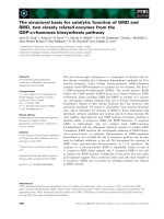
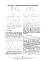
In figure 2 two examples of the analysis of one RapidArc
field relatively to the measured GLAaS dose image are
shown for 6 MV (a) and 18 MV (b). In the first column,
the computed (Eclipse) dose maps are shown. In the sec-
ond column the gamma maps are reproduced. The GLAaS
dose matrices are reproduced in the third column while in
the last column, an example of profile comparisons in the
y direction is presented. It can be seen how collapsing the
entire delivery onto a single plane introduces back into
the delivery the tongue and groove pattern that would be
smeared out (and almost cancelled) in the clinical case.
Summary of the results of the full arc deliveries is pre-
sented in table 1, with the GAI averaged over all the seven
plans (DTA = 3 mm, ΔD = 3%), as well as the MI for the
calculated and measured dose maps, for both 6 and 18
MV. GAI was better than 95% for all cases at 6 MV and in
average for 18 MV (with ~93% as minimum agreement).
The MI of the calculated dose map is lower than the MI for
measurements of about 8% for 6 MV, and the difference is
statistically significant (p = 0.001 with a paired t-test). As
a confirmation of the influence of calculation grid (or
detector resolution), the average MI of dose maps at 6 MV
computed with a 2.5 mm calculation grid is 15.9 ± 2.7
(instead of 17.0 at 1 mm). This value is 14% lower than
the MI from GLAaS and corresponds to smoother dose
calculations if compared to the 1 mm case. This feature
would be reflected also in lower GAI if 2.5 mm calcula-
tions would be used for comparison. In this latter case the
average GAI (6 MV) was 93.9 ± 2.4% with a minimum of
91.6%.
Evaluation of the data with different ΔD is reported in
table 2. For ΔD = 2% the agreement is, as expected poorer,
but it shall also be noticed that in this case value of the SD
is higher while it decreases when increasing ΔD. ΔD
thresholds should therefore be tuned also to balance
between desired precision and noise.
Apparent PV displacement relatively to the centre of rotation for a small field during full rotation in both directions (x and y), for clockwise and counter clockwise rotationsFigure 1
Apparent PV displacement relatively to the centre of rotation for a small field during full rotation in both directions (x and y),
for clockwise and counter clockwise rotations.
Radiation Oncology 2008, 3:24 />Page 6 of 10
(page number not for citation purposes)
Examples of QA for RapidArc plansFigure 2
Examples of QA for RapidArc plans. Columns refer to: Eclipse dose map, gamma evaluation map, GLAaS dose map, and profile
in a longitudinal direction. (a) 6 MV, (b) 18 MV.
Patient1
Patient2
Eclipse calc.
Gamma eval.
GLAaS meas.
y profile
Dose
Gamma
Patient1Patient2
y profile
Eclipse calc.
Gamma eval.
GLAaS meas.
Dose
Gamma
(a)
(b)
Radiation Oncology 2008, 3:24 />Page 7 of 10
(page number not for citation purposes)
Interrupted arcs
Figure 3 shows the GLAaS dose (first row) and the gamma
evaluation matrix (second row) for one plan and the three
sub-arcs for the 6 and 12° gantry movement.
In table 3 the GAI results are reported as mean values and
standard deviations of all the acquisitions per each gantry
interval. Also the mean values and standard deviations, as
well as the range, are reported as global mean of all the 6°
and 12° sub-arcs (both patients, the three acquisitions per
sub-arc). Those values, both for 6 and 12° sub-arcs (GAI
= 97 and 98%), are consistent with the corresponding full
arcs (GAI = 97%).
The results show better figures for larger arc intervals for
two reasons. Firstly the low number of MU for very small
arcs (in average 11 MU for 6°, 21 MU for 12° arcs)
enhances the uncertainty in measurements. Secondly the
highly jagged shape of the irradiated area, with regions
presenting alternate open and closed leaves enhances the
role of small discrepancies between measurements and
calculations of leaf edge penumbra due to the different
spatial resolutions.
Nevertheless, repeated measurements of small arcs
resulted in reproducible findings. The maximum observed
variation of the GAI during the three acquisitions was of
1.3%, with a mean variation of 0.7 ± 0.4%. This is a con-
firmation of the stability of the delivery, even in case of
small arcs. Plots of the repeatability over the three acqui-
sitions in all cases are shown in figure 4, where all the GAI
values are reported.
4. Discussion and conclusion
The usage of GLAaS to perform RapidArc pre-treatment
quality assurance, and in principle also any machine QA
based on modulated arcs, was presented in the present
report. RapidArc is a novel approach to intensity modu-
lated arc therapy with linacs. With RapidArc, in addition
to MLC based modulation, also the dose rate and the gan-
try rotation speed are varied during delivery to enhance
the modulation degree. Principal aim of RapidArc is to
deliver plans of high conformal avoidance with a single
arc and minimal delivery time. Dedicated quality assur-
ance processes are being developed by first RapidArc users
in the Council of Developers and investigations on GLAaS
belong to this category. The main benefits of GLAaS
applied to RapidArc can be summarized as follows: i)
GLAaS performances were proven for static field dynamic
IMRT and for standard machine quality assurance [8-10];
ii) GLAaS makes usage of the PV-aS1000 (or PV-aS500),
integrated in the delivery system and does not require
complementary phantoms or external systems; iii) GLAaS
allows to convert measured data into absolute doses at
d
max
and to directly compare these against calculations
from the planning system; iv) the spatial resolution of the
PV-aS1000 is superior to other currently available system.
Concerning spatial resolution, it was shown in this report
that care shall be put in selecting appropriate experimen-
tal settings to minimize perturbations. Particularly, if
GLAaS dosimetry with the PV-aS1000 is used, the dose
calculation grid in the planning system should be the fin-
est possible. On the other hand, with GLAaS it is possible,
in the composite and in the short arc modes, to identify
eventual computational problems that are hardly detecta-
ble by other systems. The analysis of Modulation Index
helped to investigate more the agreement between data-
sets and the relevance of calculation grid resolution. The
observed difference in MI between calculation and deliv-
ery derives from two possible sources. A dose calculation
grid of 1 mm could be still too coarse for a detector with
~0.4 mm spatial resolution (but 1 mm is the minimum
value selectable in Eclipse). The creation of composite ver-
ification plans could introduce some bias (either smooth-
ing or enhancing modulation) in the calculation or in the
delivery. Nevertheless the difference observed in MI, even
if statistically significant, was found to be small in abso-
lute terms.
Some items are specific of arc based delivery and to the
specific RapidArc implementation and should be
addressed for GLAaS. Concerning arcs, the first problem
was the assessment of the magnitude of the apparent dis-
placement of the detector with respect to the rotational
Table 1: Summary of the GLAaS results in terms of GAI and MI.
Energy GAI [%] MI calc MI GLAaS
6 MV Mean 96.7 ± 1.2 17.0 ± 3.2 18.5 ± 3.7
Range [95.3, 98.5] [11.4, 20.3] [11.9, 22.2]
18 MV Mean 94.9 ± 1.3 15.3 ± 2.7 17.5 ± 3.7
Range [92.9, 96.2] [11.3, 18.8] [11.8, 21.8]
Table 2: Summary of the GLAaS results: GAI values for different threshold criteria.
Energy GAI [%]
DTA, ΔD = 3 mm,2%
GAI [%]
DTA, ΔD = 3 mm,3%
GAI [%]
DTA, ΔD = 3 mm,4%
6 MV 93.4 ± 3.2 96.7 ± 1.2 98.3 ± 0.8
18 MV 90.1 ± 3.1 94.9 ± 1.3 97.3 ± 0.9
Radiation Oncology 2008, 3:24 />Page 8 of 10
(page number not for citation purposes)
GLAaS dose and gamma evaluation maps for the three consecutive sub-arcs of: (a) 6 degree, (b) 12 degreeFigure 3
GLAaS dose and gamma evaluation maps for the three consecutive sub-arcs of: (a) 6 degree, (b) 12 degree.
CP 2-5
CP 5-8
CP 8-11
GLAaS
Gamma eval.
(a)
CP 2-8
CP 8-14
CP 14-20
GLAaS
Gamma eval.
(b)
Radiation Oncology 2008, 3:24 />Page 9 of 10
(page number not for citation purposes)
axis (due to both gantry sag and real detector mechanical
instability). The movement along the transversal direction
was considered as negligible since it is of the same magni-
tude of the PV pixel size. Along the longitudinal direction
x, about one third of the whole rotation present a dis-
placement inferior to 1–1.5 mm. This value is roughly one
third of the penumbra of the lateral leaf's edge. These two
reasons (only 30% of the delivery is affected and the cor-
relation to penumbra size) allowed the decision to
exclude from the GLAaS development for arc the need, at
first order, of dedicated corrections for the apparent detec-
tor displacement with respect to the axis of rotation.
Would a specific system require it, it would be possible to
implement an off line correction. A feasibility test was per-
formed by applying or not to GLAaS such a correction.
The difference was negligible, and the GAI difference
between the two cases was less than 0.5%.
A second item was linked to the usage of variable dose rate
during delivery. This issue was not addressed in this report
since it was already investigated for Enhanced Dynamic
Wedges in [10]. In that report it was shown how GLAaS
based dosimetry is independent from the dose rate due to
the characteristics of the PV-aS detectors.
Onether potential limitation to mentione is that, what-
ever the collimator angle, being the detector integral with
the gantry, the residual tongue and groove effect is
brought back in the measurements as noticed in figures 2
and 3. This is likely the main contributor to the GAI devi-
ation from 100% but, as results proved, it does not com-
promise the high quality of results. The presence of the
tongue and groove patterns would be solved if the detec-
tor would be detached from the gantry and left fixed on
the couch. Another issue to mention is that, RapidArc ver-
ification through composite planes does not allow any
direct verification of the gantry rotation and that fluctua-
tions linked to this are eventually lost. To minimize the
relevance of this limitation, partial short arcs should be
verified and included in the standard procedures. The
application of GLAaS to short arcs would also basically
solve the issue of tongue and groove effect (at least would
not enhance it through its pile-up)
Notwithstanding the above limitations, the results sum-
marised in this report are quite satisfactory. In the com-
posite mode, average GAI equal or higher than 95% were
obtained for both low and high energy modes and the
range of findings never fell below 90%. These results are
consistent with the current clinical experience from
GLAaS applied to standard IMRT verification where, at
low energy, an average GAI of ~98% is observed [9]. At
low energy, the tests performed on short arcs showed sim-
ilar results with GAI higher than 96% and with a highly
Table 3: Summary of the interrupted arc analysis
Arc interval GAI [%] mean ± SD GAI [%] Range
178.0–171.8° 96.0 ± 0.7
171.8–165.7° 97.0 ± 0.8
165.7–159.6° 97.2 ± 0.7
6° 96.7 ± 0.9% [95.1, 98.0]
178.0–165.7° 98.6 ± 0.5
165.7–153.4° 97.8 ± 0.2
153.4–141.2° 96.6 ± 0.9
12° 98.0 ± 1.1% [95.6, 99.0]
GAI results (DTA = 3 mm, ΔD = 3%) for all acquisition of sub-arcs findings showing repeated measurementsFigure 4
GAI results (DTA = 3 mm, ΔD = 3%) for all acquisition of sub-arcs findings showing repeated measurements.
Publish with BioMed Central and every
scientist can read your work free of charge
"BioMed Central will be the most significant development for
disseminating the results of biomedical research in our lifetime."
Sir Paul Nurse, Cancer Research UK
Your research papers will be:
available free of charge to the entire biomedical community
peer reviewed and published immediately upon acceptance
cited in PubMed and archived on PubMed Central
yours — you keep the copyright
Submit your manuscript here:
/>BioMedcentral
Radiation Oncology 2008, 3:24 />Page 10 of 10
(page number not for citation purposes)
reproducible pattern for repeated measures on the short
term.
In absence of any general consensus on acceptance levels
for modulated arc delivery, it is authors opinion that a
threshold to GAI = 95% could be applied to define accept-
able pre-treatment delivery verifications. For GAI in the
range between 90 and 95% care should be paid to investi-
gate more in detail potential sources of errors by perform-
ing complementary tests (e.g. controlling leaf motion,
dose rate or gantry speed performances). GAI should
likely be computed with DTA = 3 mm and ΔD = 3% since
calculation uncertainties from TPS and detector vs. calcu-
lation spatial resolution issues would weaken reliability of
findings optained with more stringent parameters.
To conclude, GLAaS can be considered as a promising
approach to RapidArc delivery Quality Assurance in both
the composite and short arcs approaches. Further devel-
opment are needed to make the short arc more automatic
but do not require changes to the model. At the same
time, RapidArc delivery was tested for a variety of different
indications and results are satisfactory and allow consid-
ering safe its clinical introduction.
Competing interests
The authors declare that they have no competing interests.
Dr Luca Cozzi acts as scientific consultant to Varian Med-
ical Systems AG. Jiri Bocanek is a Varian Medical System
employee.
Authors' contributions
GN, AF and LC designed the study. LC wrote the manu-
script. GN, EV, AC, SK, JB performed data acquisition and
processing. AF, GN, LC, EV and AC developed the algo-
rithms. EV, AC and GN wrote the computer programmes.
All authors reviewed and approved the manuscript.
References
1. Berger L, François P, Gaboriaud G, Rosenwald JC: Performance
optimization of the Varian aS500 EPID system. J Appl Clin Med
Phys 2006, 7:105-114.
2. Greer PB, Popescu CC: Dosimetric properties of an amorphous
silicon electronic portal imaging device for verification of
dynamic intensity modulated radiation therapy. Med Phys
2003, 30:1618-1627.
3. Greer PB: Off-axis dose response characteristics of an amor-
phous silicon electronic portal imaging device. Med Phys 2007,
34:3815-3824.
4. Greer PB, Vial P, Oliver L, Baldock C: Experimental investigation
of the response of an amorphous silicon EPID to intensity
modulated radiotherapy beams. Med Phys 2007, 34:4389-4398.
5. Grein EE, Lee R, Luchka K: An investigation of a new amorphous
silicon portal imaging device for transit dosimetry. Med Phys
2002, 29:2262-2268.
6. Parent L, Fielding AL, Dance DR, Seco J, Evans PM: Amorphous sil-
icon EPID calibration for dosimetric applications: compari-
son of a method based on Monte Carlo prediction of
response with existing techniques. Phys Med Biol 2007,
52:3351-3368.
7. Winkler P, Hefner A, Georg D: Dose-response characteristics of
an amorphous silicon EPID. Med Phys 2005, 32:3095-3105.
8. Nicolini G, Fogliata A, Vanetti E, Clivio A, Cozzi L: GLAaS: an abso-
lute dose calibration algorithm for an amorphous silicon por-
tal imager. Applications to IMRT verification. Med Phys 2006,
33:2839-2851.
9. Nicolini G, Fogliata A, Vanetti E, Clivio A, Vetterli D, Cozzi L: Test-
ing the GLAaS algorithm for dose measurements on an
amorphous silicon portal imager on low and high energy
photon beams. Med Phys 2008, 35:464-472.
10. Nicolini G, Vanetti E, Clivio A, Fogliata A, Boka G, Cozzi L: Testing
the portal imager GLAaS algorithm for machine quality
assurance. Radiat Oncol 2008, 3:14.
11. Duthoy W, De Gersem W, Vergote K, et al.:
Clinical implementa-
tion of intensity-modulated arc therapy (IMAT) for rectal
cancer. Int J Radiat Oncol Biol Phys 2004, 60:794-806.
12. Earl MA, Shepard DM, Naqvi S, Li XA, Yu CX: Inverse planning for
intensity-modulated arc therapy using direct aperture opti-
mization. Phys Med Biol 2003, 48:1075-89.
13. Wong E, Chen JZ, Greenland J: Intensity-modulated arc therapy
simiplified. Int J Radiat Oncol Biol Phys 2002, 53:222-35.
14. Yu CX: Intensity modulated arc therapy with dynamic multi-
leaf collimation: an alternative to TomoTherapy. Phys Med
Biol 1995, 40:1435-49.
15. Yu CX, Li XA, Ma L, et al.: Clinical Implementation of intensity-
modulated arch therapy. Int J Radiat Oncol Biol Phys 2002,
53:453-63.
16. van Esch A, Clermont C, Devillers M, Iori M, Huyskens DP: On-line
quality assurance of rotational radiotherapy treatment
delivery by means of a 2D ion chamber array and the
Octavius phantom. Med Phys 2007, 34:3825-37.
17. Otto K: Volumetric modulated arc therapy: IMRT in a single
gantry arc. Med Phys 2008, 35:310-7.
18. Low DA, Harms WB, Mutic S, Purdy JA: A technique for the quan-
titative evaluation of dose distributions. Med Phys 1998,
25:656-660.
19. Webb S: Use of a quantitative index of beam modulation to
characterize dose conformality: illustration by a comparison
of full beamlet IMRT, few-segment IMRT (fsIMRT) and con-
formal unmodulated radiotherapy. Phys Med Biol 2003,
48:2051-2062.
20. Nicolini G, Fogliata A, Vanetti E, Clivio A, Ammazzalorso F, Cozzi L:
What is an acceptably smoothed fluence? Dosimetric and
delivery considerations for dynamic sliding window IMRT.
Radiat Oncol 2007, 2:42.