autocad 2008 autocad lt 2008 no experience required - phần 2 ppt
Bạn đang xem bản rút gọn của tài liệu. Xem và tải ngay bản đầy đủ của tài liệu tại đây (1.13 MB, 73 trang )
FIGURE 2.22: Lines are trimmed to make the opening.
NOTE
If you trim the wrong line or wrong part of a line, you can click
the Undo button on the Standard toolbar. This undoes the last trim without
canceling the Trim command, and you can try again.
Now let’s remove the extra part of the trimming guidelines:
1. Press ↵ twice—once to end the Trim command and again to restart it.
This will let you pick new cutting edges for another trim operation.
2. Pick the two upper horizontal lines next to the opening as your cut-
ting edges, shown in Figure 2.23, and press ↵.
FIGURE 2.23: Lines picked to be cutting edges
Cutting edges
Completing the Box 49
26531ch02.qxd 3/30/07 5:01 PM Page 49
3. Pick the two vertical lines that extend above the new opening. Be
sure to pick them above the opening (see Figure 2.24). The lines are
trimmed away, and the opening is complete. Press ↵ to end the Trim
command (see Figure 2.25).
FIGURE 2.24: Lines picked to be trimmed
FIGURE 2.25: The completed trim
Congratulations! You’ve just completed the first drawing project in this book
using all the tools covered in this chapter. These skills will be useful as you learn
how to work on drawings for actual projects.
Lines to be trimmed
Chapter 2 • Learning Basic Commands to Get Started50
26531ch02.qxd 3/30/07 5:01 PM Page 50
A valuable exercise at this time would be to draw this box two or three more
times, until you can do it without the instructions. This will be a confidence
builder and will get you ready to take on the new information in the next chap-
ter, where you’ll set up a drawing for a building.
The box you drew was 6 units by 5 units, but how big was it? You really don’t
know at this time, because the units could represent any actual distance: inches,
feet, meters, miles, and so on. Also, the box was positioned conveniently on the
screen so you didn’t have any problem viewing it. What if you were drawing a
building that was 200 feet long and 60 feet wide or a portion of a microchip cir-
cuit that was only a few thousandths of an inch long? In the next chapter, you’ll
learn how to set up a drawing for a project of a specific size.
You can exit AutoCAD now without saving this drawing. To do so, choose
File
➣ Exit. When the dialog box asks whether you want to save changes, click
No. Or, you can leave AutoCAD open and go to the following practice section or
the next chapter.
If You Would Like More Practice…
Draw the object shown in Figure 2.26.
FIGURE 2.26: Practice drawing
If You Would Like More Practice… 51
26531ch02.qxd 3/30/07 5:01 PM Page 51
You can use the same tools and strategy used to draw the box. Choose File ➣
New to start a new drawing, and then use the acad.dwt template file. Here’s a
summary of the steps to follow:
1. Ignore the three openings at first.
2. Draw the outside edge of the shape using one of the relative coordi-
nate systems. To make sure the box fits on your screen, start the out-
line of the box in the lower-left corner at the absolute coordinate
of 1,0.5.
3. Offset the outside lines to create the inside wall.
4. Fillet the corners to clean them up. (Lines that aren’t touching can
be filleted just like lines that intersect.)
5. Use the Offset, Extend, and Trim commands to create the three
openings.
Don’t worry about trying to put in the dimensions, centerline, or hatch lines.
You’ll learn how to create those objects later in the book.
Are You Experienced?
Now you can…
0 understand the basics of coordinates
0 discern between absolute and the two relative coordinate
systems used by AutoCAD
0 use the Line, Erase, Offset, Fillet, Extend, and Trim commands
to create a drawing
Chapter 2 • Learning Basic Commands to Get Started52
26531ch02.qxd 3/30/07 5:01 PM Page 52
CHAPTER 3
Setting Up
a Drawing
Ǡ
Setting up drawing units
Ǡ
Using AutoCAD’s grid
Ǡ
Zooming in and out of a drawing
Ǡ
Naming and saving a file
26531ch03.qxd 3/30/07 5:03 PM Page 53
I
n Chapter 2, you explored the default drawing area that is set up when you
open a new drawing. It’s probably 9 units high by 12 to 16 units wide, depend-
ing on the size of your monitor. You drew a box within this area. If you drew
the additional diagram offered as a supplemental exercise, the drawing area
was set up the same way.
For most of the rest of this book, you’ll be developing drawings for a cabin with
outside wall dimensions of 25'
× 16', but the tools you use and the skills you learn
will enable you to draw objects of any size. In this chapter, you’ll learn how to set
up the drawing area to lay out the floor plan for a building of a specific size. You’ll
change the decimal units with which you have been drawing until now to feet and
inches, and you’ll transform the drawing area so it can represent an area large
enough to display the floor plan of the cabin you’ll be drawing.
I’ll introduce you to some new tools that will help you visualize the area your
screen represents and allow you to draw lines to a specified incremental dis-
tance, such as to the nearest foot. Finally, you’ll save this drawing to a special
folder on your hard disk. At the end of the chapter is a general summary of the
various kinds of units that AutoCAD supports.
Setting Up the Drawing Units
When you draw lines of a precise length in AutoCAD, you use one of five kinds of
linear units. Angular units can also be any of five types. You can select the type of
units to use, or you can accept the default decimal units that you used in the
previous chapter.
When you start a new drawing, AutoCAD displays a blank drawing called
Drawingn.dwg with the linear and angular units set to decimal numbers. The
units and other basic setup parameters applied to this new drawing are based on
a prototype drawing with default settings—including those for the units. This
chapter covers some of the tools for changing the basic parameters of a new
drawing so you can tailor it to the cabin project or for your own project. Begin
by setting up new units:
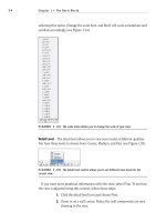
1. With AutoCAD running, close all drawings, and then click the New
button (on the Standard toolbar) to start a new drawing. In the Select
Template dialog box, click the arrow to the right of the Open button,
and select Open with No Template – Imperial (see Figure 3.1).
To get started with the steps in this chapter, check to be sure that, for
now, all the status bar buttons except Model are clicked to the off
position—that is, they appear unpushed. When we get to Chapter 10,
you’ll see how to use templates to set up drawings.
Chapter 3 • Setting Up a Drawing54
26531ch03.qxd 3/30/07 5:03 PM Page 54
FIGURE 3.1: The Select Template dialog box
2. Choose Format ➣ Units to open the Drawing Units dialog box (see
Figure 3.2). In the Length area, Decimal is currently selected. Simi-
larly, in the Angle area, Decimal Degrees is the default.
NOTE
You might notice that several items listed in the menus are fol-
lowed by an ellipsis (…). The ellipsis indicates that the option opens a dialog
box, rather than executing a command. The same convention applies to but-
tons with ellipses included on their labels.
FIGURE 3.2: The Drawing Units dialog box
Setting Up the Drawing Units 55
ǡ
You can also open
the Drawing Units
dialog box by
typing un↵.
26531ch03.qxd 3/30/07 5:03 PM Page 55
3. In the Length area, click the arrow in the Type drop-down list, and
select Architectural. These units are feet and inches, which you’ll use
for the cabin project.
Notice the two Precision drop-down lists at the bottom of the Length
and Angle areas. When you changed the linear units specification
from the Decimal setting to the Architectural setting, the number in
the Precision drop-down list on the left changed from 0.0000 to
0'-0 1/16". At this level of precision, linear distances are displayed
to the nearest 1/16".
4. Select some of the other Length unit types from the list, and notice
the way the units appear in the Sample Output area at the bottom
of the dialog box. Then select Architectural again.
NOTE
Drop-down lists are lists of choices with only the selected choice
displayed. When you click the arrow, the list opens. When you make another
selection, the list closes, and your choice is displayed. When an item on the
list is selected and is the focus of the program, indicated by a blue highlight,
you can change the available options using the scroll wheel on a mouse or the
up and down arrows on the keyboard.You can choose only one item at a time
from the list.
5. Click the arrow in the Precision drop-down list in the Length area to
display the choices of precision for architectural units (see Figure 3.3).
This setting controls the degree of precision to which AutoCAD dis-
plays a linear distance. If it’s set to 0'-0 1/16", any line that is drawn
more precisely—such as a line 6'-3
1
⁄32" long, when queried, displays a
length value to the nearest
1
⁄16" or, in the example, as 6'-3
1
⁄16". But the
line is still 6'-3
1
⁄32" long.
If you change the precision setting to 0'-0 1/32" and then use the Dis-
tance command (explained in Chapter 7) to measure the line, you’ll
see that its length is 6'-3
1
⁄32".
6. Click 0'-0 1/16" to maintain the precision for display of linear units
at
1
⁄16".
Chapter 3 • Setting Up a Drawing56
26531ch03.qxd 3/30/07 5:03 PM Page 56
FIGURE 3.3: The Precision drop-down list for architectural units
If you open the Type drop-down list in the Angle area, you see a choice
between Decimal Degrees and Deg/Min/Sec, among others. Most AutoCAD users
find the decimal angular units the most practical, but the default precision set-
ting is to the nearest degree. This might not be accurate enough, so you should
change it to the nearest hundredth of a degree:
1. Click the arrow in the Precision drop-down list in the Angle area.
2. Click 0.00. The Drawing Units dialog box will now indicate that, in
your drawing, you plan to use architectural length units with a pre-
cision of
1
⁄16" and decimal angular units with a precision of 0.00 (see
Figure 3.4). This doesn’t restrict the precision at which you draw,
just the values that AutoCAD reports.
FIGURE 3.4: The Drawing Units dialog box after changes
Setting Up the Drawing Units 57
26531ch03.qxd 3/30/07 5:03 PM Page 57
Clicking the Direction button at the bottom of the Drawing Units dialog
box opens the Direction Control dialog box, which has settings to con-
trol the direction of 0 degrees. By default, 0 degrees is to the right (east),
and positive angular displacement goes in counterclockwise direction.
(See Figure 2.7 in Chapter 2 for an explanation.) These are the standard
settings for most uses of CAD. You don’t need to change them from the
defaults. If you want to take a look, open the Direction Control dialog
box, note the choices, and then click OK. You won’t have occasion in the
course of this book to change any of those settings.
NOTE
You’ll have a chance to work with surveyor’s angular units later
in the book, in Chapter 12, when you develop a site plan for the cabin.
3. Click OK in the Drawing Units dialog box to accept the changes and
close the dialog box. Notice the coordinate readout in the lower-left
corner of the screen: it now displays in feet and inches.
This tour of the Drawing Units dialog box has introduced you to the choices
you have for the types of units and the degree of precision for linear and angular
measurement. The next step in setting up a drawing is to determine its size.
NOTE
If you accidentally click when the cursor is on a blank part of the
drawing area, AutoCAD starts a rectangular window. I’ll talk about these win-
dows soon, but for now, just press the Esc key to close the window.
Setting Up the Drawing Size
As you discovered earlier, the default drawing area on the screen for a new draw-
ing is 12 to 16 units wide and 9 units high. After changing the units to architec-
tural, the same drawing area is now 12 to 16 inches wide and 9 inches high. You
can check this by moving the crosshair cursor around on the drawing area and
looking at the coordinate readout, as you did in the previous chapter.
TIP
When you change decimal units to architectural units, 1 decimal unit
translates to 1 inch. Some industries, such as civil engineering, often use deci-
mal units to represent feet instead of inches. If the units in their drawings are
switched to architectural units, a distance that was a foot now measures as an
inch. To correct this, you must scale the entire drawing up by a factor of 12.
Chapter 3 • Setting Up a Drawing58
26531ch03.qxd 3/30/07 5:03 PM Page 58
As you know, the drawing area is defined as the part of the screen in which
you draw. You can make the distance across the drawing area larger or smaller
through a process known as zooming in or zooming out. To see how this works,
you’ll learn about a tool called the grid that helps you draw and visualize the size
of your drawing.
Using the Grid
The AutoCAD grid is a pattern of regularly spaced dots used as an aid to drawing.
You can set the grid to be visible or invisible. The area covered by the grid depends
on the Drawing Limits setting. To learn how to manipulate the grid size, you’ll
make the grid visible, use the Zoom In and Zoom Out commands to vary the view
of the grid, and then change the area over which the grid extends by resetting the
drawing limits. Before doing this, however, let’s turn off the UCS icon that cur-
rently sits in the lower-left corner of the drawing area. You’ll display it again and
learn how to use it in Chapter 10.
1. At the
Command: prompt, enter ucsicon↵, and then type off↵. The
icon disappears.
2. At the
Command: prompt, move the crosshair cursor to the status bar
at the bottom of the screen, and click the Grid button. The button
appears to have been pushed down, and dots appear on most of the
drawing area (see Figure 3.5). These dots are the grid. They are preset
by default to be
1
⁄2" apart, and they extend from the 0,0 point (the ori-
gin) out to the right and up to the coordinate point 1'-0",0'-9".
FIGURE 3.5: The AutoCAD grid
Setting Up the Drawing Size 59
ǡ
You can also control
the visibility of the
UCS icon by choosing
View
➣ Display ➣
UCS Icon ➣ On. If
On has a checkmark,
clicking it turns off
the UCS icon. If it
doesn’t, clicking turns
the icon back on.
26531ch03.qxd 3/30/07 5:03 PM Page 59
3. Right-click the Grid button and then choose Settings from the con-
text menu that appears to open the Drafting Settings dialog box.
TIP
Right-clicking any of the buttons on the status bar (except Ducs,
Lwt, Ortho, or Model) and choosing Settings opens the Drafting Settings dia-
log box to the tab with the parameters that relate to the specific button. You
can also open the Drafting Settings dialog box by typing ds↵ or by choosing
Tools
➣ Drafting Settings from the menu bar.
4. The Snap and Grid tab should be active (see Figure 3.6). If it’s not,
click the tab. In the Grid Behavior area, be sure Adaptive Grid and
Display Grid Beyond Limits are checked. Then click OK. The grid
now covers the area only from 0',0" to 1',9", the area defined by the
limits of the drawing. (I’ll discuss limits in the next section.) The
Adaptive Grid options causes AutoCAD to proportionately reduce the
number of the grid’s columns and rows whenever the zoom factor
would cause the grid to become too dense to be effective.
FIGURE 3.6: The Snap and Grid tab of the Drafting Settings dialog box
Chapter 3 • Setting Up a Drawing60
26531ch03.qxd 3/30/07 5:03 PM Page 60
Notice that rows of grid dots run right along the left edge, top, and
bottom of the drawing area, but the dots don’t extend all the way to
the right side. The grid dot at the 0'0", 0'0" point is positioned exactly
at the lower-left corner of the screen, and the grid dot at 1'-0",0'-9" is
on the top edge, not too far from the upper-right corner.
5. For a better view of the entire grid, use the Zoom Out command.
Choose View
➣ Zoom ➣ Out or choose Zoom Out from the Zoom
fly-out menu on the Standard toolbar. The view changes, and there
are fewer grid dots (see Figure 3.7). You might need to perform the
zoom twice to see the effect. Move the crosshair cursor to the lower-
left corner of the grid, and then move it to the upper-right corner.
Notice the coordinate readout in the lower left of your screen. These
two points should read as approximately 0'-0",0'-0" and 0'-10",0'-7
1
⁄2",
respectively.
FIGURE 3.7: The grid after zooming out
6. On the status bar, next to the Grid button, click the Snap button;
then, move the cursor back onto the grid, and look at the coordinate
readout again. The cursor stops at each grid point, even those that
are no longer displayed because of the zoom factor, and the readout is
to the nearest half inch. Now, when you place the crosshair cursor on
the lower-left corner of the grid, the readout is exactly 0'-0",0'-0", and
it’s 0'-10",0'-7
1
⁄2" for the upper-right corner. The Snap tool locks the
cursor onto the grid dots; even when the cursor isn’t on the grid but
somewhere outside it on the drawing area, the cursor maintains the
grid spacing and jumps from one location to another.
Setting Up the Drawing Size 61
26531ch03.qxd 3/30/07 5:03 PM Page 61
7. Use the Zoom Out command a few more times.
8. Choose View
➣ Zoom ➣ In or use the scroll wheel on your mouse
enough times to bring the view of the grid back to the way it was in
Figure 3.5. You aren’t changing the size of the grid, just the view of it.
It’s like switching from a regular lens to a telephoto lens on a camera.
The grid is more a guide than an actual boundary of your drawing. You can
change a setting to force lines to be drawn only in the area covered by the grid,
but this isn’t ordinarily done. For most purposes, you can draw anywhere on the
screen. The grid merely serves as a tool for visualizing how your drawing will be
laid out.
Because it serves as a layout tool for this project, you need to increase the area
covered by the grid from its present size of 1'
× 9" to 60' × 40'. Because the Draw-
ing Limits setting controls the size of the grid, you need to change it.
Setting Up Drawing Limits
The Drawing Limits setting records the coordinates of the lower-left and upper-
right corners of the grid. The coordinates for the lower-left corner are 0,0 by
default and are usually left at that setting. You need to change the coordinates
only for the upper-right corner:
1. Be sure the Command window displays the
Command: prompt; then
choose Format
➣ Drawing Limits, or enter limits↵. Notice how the
Command window has changed.
The bottom command line tells you that the first step is to decide
whether to change the default X and Y coordinates for the lower-left
limits, both of which are currently set at 0',0". You don’t need to
change these.
2. Press ↵ to accept the 0'0", 0'0" coordinates for this corner. The bot-
tom command line changes and now displays the coordinates for the
upper-right corner of the limits. This is the setting you want to
change.
3. Enter 60',40'↵. Be sure to include the foot sign (').
Chapter 3 • Setting Up a Drawing62
26531ch03.qxd 3/30/07 5:03 PM Page 62
NOTE
AutoCAD requires that, when using architectural units, you
always indicate that a distance is measured in feet by using the foot sign (').
You don’t have to use the inch sign (") to indicate inches.
The grid now appears to extend to the top-right edge of the drawing
area (see Figure 3.8), but it actually extends far past the edges. It was
1 foot wide, and now it’s 60 times that, but the drawing area shows
only the first foot or so.
FIGURE 3.8: The same view with the grid extended to 60' × 40'
4. To bring the whole grid onto the screen, use the Zoom command
again, but this time use the All option: choose View
➣ Zoom ➣ All, or
enter z↵ a↵. The grid fills the screen, but there are fewer dots. The
All option zooms the view to display all the objects in the drawing or,
in a blank drawing, zooms to the limits.
5. Move the cursor from one dot to another, and watch the coordinate
readout. The coordinates are still displayed to the nearest half inch,
but the dots are much more than half an inch apart.
By default, when you zoom in or out, AutoCAD adjusts the grid spacing to keep
the dots from getting too close together or too far apart. In this case, remember
that you found the grid spacing to be
1
⁄2" by default. If the drawing area is giving
you a view of a 60'
× 40' grid with dots at
1
⁄2", the grid is 1,440 dots wide and 960
dots high. If the whole grid were to be shown on the screen, the dots would be so
close together that they would be about only 1 pixel in size and would solidly fill
Setting Up the Drawing Size 63
26531ch03.qxd 3/30/07 5:03 PM Page 63
the drawing area. So, AutoCAD adjusts the spacing of the dots to keep the grid
readable. You need to change that spacing.
For the drawing task ahead, it will be more useful to have the spacing set dif-
ferently. Remember how you turned on Snap and the cursor stopped at each dot?
If you set the dot spacing to 12", you can use Grid and Snap modes to help you
draw the outline of the cabin, because the dimensions of the outside wall line are
in whole feet: 25'
× 16'. Here’s how:
1. Right-click the Grid button on the status bar, and choose Settings
from the context menu that opens. The Drafting Settings dialog box
opens, and the Snap and Grid tab is active. The settings in both the
Grid and Snap areas include X Spacing and Y Spacing settings. Notice
that they’re all set for a spacing of
1
⁄2".
2. In the Grid area, click in the Grid X Spacing text box, and change 1/2"
to 4'. Then, click the Grid Y Spacing text box. It automatically changes
to match the Grid X Spacing text box. If you want different Grid X
and Grid Y Spacing values, you must uncheck the Equal X and Y
Spacing option in the Snap Spacing area.
3. In the Snap section, change the Snap X Spacing setting to 12. The
inch sign isn’t required. Then, click the Snap Y Spacing setting. It
automatically changes to match the Snap X Spacing setting and
changes both text boxes to display 1' instead of 12" (see Figure 3.9).
FIGURE 3.9: New settings on the Snap and Grid tab of the Drafting Set-
tings dialog box
Chapter 3 • Setting Up a Drawing64
Ǡ
If you set the Grid
Spacing to 0, the grid
takes on whatever
spacing you set for
the Snap X Spacing
and Snap Y Spacing
text boxes. This is
how you lock the
snap and grid
together.
26531ch03.qxd 3/30/07 5:03 PM Page 64
4. In the Snap Type area, be sure Grid Snap and Rectangular Snap are
selected.
5. In the Grid Behavior area, only Adaptive Grid should be checked.
With the grid set this way, AutoCAD will adjust the number of dots
displayed as you zoom in and out but won’t add dots between the low-
est grid spacing.
6. The Snap On and Grid On check boxes at the top of the dialog box
should be selected. If they aren’t, click them.
7. Click OK. The new 4' grid is now visible (see Figure 3.10). Move the
cursor around on the grid—be sure Snap is on. (Check the Snap but-
ton on the status bar; it’s pressed when Snap is on.) Notice the coor-
dinate readout. It’s displaying coordinates to the nearest foot to
conform to the new 12" snap spacing. The cursor stops at three snap
points between each grid dot.
FIGURE 3.10: The new 60' × 40' grid with 4' dot spacing
8. Move the crosshair cursor to the upper-right corner of the grid, and
check the coordinate readout. It should display 60'-0", 40'-0", 0'-0".
(In LT, you won’t have the third coordinate.)
Setting Up the Drawing Size 65
26531ch03.qxd 3/30/07 5:03 PM Page 65
Drawing with Grid and Snap
Your drawing area now has the proper settings and is zoomed to a convenient
magnification. You’re ready to draw the first lines of the cabin:
1. When the Command window displays the
Command: prompt, start the
Line command. (Click the Line button on the Draw toolbar, or enter
l↵.) Enter 8',8'↵ (see Figure 3.11).
FIGURE 3.11: One point picked on the grid
2. On the status bar, click Dyn to activate dynamic display, and then
hold the crosshair cursor above and to the right of the point you just
picked. AutoCAD shows dashed linear and angular dimensions that
dynamically display the length and angle of the first line segment as
the cursor moves, and a tooltip displays the current prompt for the
Line command.
3. Don’t click yet. Hold the crosshair cursor directly out to the right of
the first point picked, and note how the linear dimension displays a
distance in whole feet. The angular dimension should have an angle
of 0.00°.
Length
Prompt
Angle
Chapter 3 • Setting Up a Drawing66
26531ch03.qxd 3/30/07 5:03 PM Page 66
4. Continue moving the crosshair cursor left or right until the dashed
linear dimension displays 25'. At this point, click the left mouse but-
ton to draw the first line of the cabin wall (see Figure 3.12).
FIGURE 3.12: Drawing the first line of the cabin wall
5. Move the crosshair cursor directly above the last point picked to a
position such that the dashed linear dimension displays 16' and the
dashed angular dimension displays 90.00°, and pick that point.
6. Move the crosshair cursor directly left of the last point picked until
the dashed linear dimension displays 25' and the dashed angular
dimension displays 180.00°, and pick that point (see Figure 3.13).
FIGURE 3.13: Drawing the second and third wall lines
Drawing with Grid and Snap 67
26531ch03.qxd 3/30/07 5:03 PM Page 67
7. Finally, enter c↵ to close the box. This tells AutoCAD to draw a line
from the last point picked to the first point picked and, in effect,
closes the box. AutoCAD then automatically ends the Line command
(see Figure 3.14).
FIGURE 3.14: The completed outside wall lines
This method for laying out building lines by using Snap and Grid and the
dynamic display is useful if the dimensions all conform to a convenient rounded-
off number, such as the nearest six inches or, as in this case, the nearest foot.
The key advantage to this method over just typing the relative coordinates—as
you did with the box in Chapter 2—is that you avoid having to enter the num-
bers. You should, however, assess whether the layout you need to draw has char-
acteristics that lend themselves to using Grid, Snap, and the dynamic display or
whether typing the relative coordinates would be more efficient. As you get more
comfortable with AutoCAD, you’ll see that this sort of question comes up often:
which way is the most efficient? This happy dilemma is inevitable in an applica-
tion with enough tools to give you many strategic choices. In Chapters 4 and 5,
you’ll learn other techniques for drawing rectangles.
Chapter 3 • Setting Up a Drawing68
26531ch03.qxd 3/30/07 5:03 PM Page 68
Taking a Closer Look at Dynamic Display
The kind of information shown in dynamic display is similar to that shown in
the Command window and the intent of this feature is to keep your eyes on the
screen as much as possible. Like the information on the Command line, it
depends on what you’re doing at the time and on several settings that you access
by right-clicking the Dyn button on the status bar and selecting Settings from
the shortcut menu. This opens the Drafting Settings dialog box with the
Dynamic Input tab activated (see Figure 3.15).
FIGURE 3.15: The Dynamic Input tab of the Drafting Settings dialog box
This tab has three check boxes, two at the top and one near the middle on the
right, and three buttons to open three Settings dialog boxes. To make the dynamic
input conform to what is shown in the book, do the following:
1. Be sure all three check boxes are selected.
2. In the Pointer Input area, click the Settings button to open the Pointer
Input Settings dialog box (see Figure 3.16). In the Format area, the
Polar Format and Relative Coordinates radio buttons should be
selected. Click OK.
Taking a Closer Look at Dynamic Display 69
26531ch03.qxd 3/30/07 5:03 PM Page 69
FIGURE 3.16: The Pointer Input Settings dialog box
3. In the Dimension Input area, click the Settings button to open the
Dimension Input Settings dialog box (see Figure 3.17).
FIGURE 3.17: The Dimension Input Settings dialog box
4. Be sure the Show 2 Dimension Input Fields at a Time radio button is
selected, and then click OK.
5. Below the Dynamic Prompts area of the Drafting Settings dialog
box, click the Drafting Tooltip Appearance button to open the
Tooltip Appearance dialog box (see Figure 3.18). In the Apply To
Chapter 3 • Setting Up a Drawing70
26531ch03.qxd 3/30/07 5:03 PM Page 70
area at the bottom of the box, be sure the Use Settings Only for
Dynamic Input Tooltips radio button is selected. Vary the Colors,
Size, and Transparency settings according to your preference. (I
used a setting of 1 for Size and 0% for Transparency. Don’t worry
about Layout Color for now; you’ll come back to it in Chapter 13
when you work with layouts.) The model color you choose depends
on whether your drawing area has a light or dark background.
Experiment. When you’re finished, click OK.
FIGURE 3.18: The Tooltip Appearance dialog box
6. Click OK again to close the Drafting Settings dialog box.
If you decide to disable dynamic display, you can easily do so by clicking the
Dyn button in the status bar so that it’s in unpushed mode. After this chapter,
I’ll direct you to turn off Snap and Grid because you won’t use them for the
rest of the book. I’ll also direct you to turn off dynamic display, because it’s
generally off in the book illustrations. However, you’ll turn it back on when
you’re doing an action in which the feature might be useful. If you prefer to
keep it on, feel free to do so.
Taking a Closer Look at Dynamic Display 71
26531ch03.qxd 3/30/07 5:03 PM Page 71
Saving Your Work
As with all Windows-compliant applications, when you save a file for the first
time by choosing File
➣ Save, you can designate a name for the file and a folder
in which to store it. I recommend you create a special folder, called something
like
Training Data, for storing the files you’ll generate as you work your way
through this book. This will keep them separate from project work already on
your computer, and you’ll always know where to save or find a training drawing.
To save your drawing, follow these steps:
1. In AutoCAD, click the Save button on the Standard toolbar, or choose
File
➣ Save. Because you haven’t named this file yet, the Save Draw-
ing As dialog box opens, as shown in Figure 3.19.
FIGURE 3.19: The Save Drawing As dialog box
The Save button in the Standard toolbar, the Save menu item, and
the Ctrl+S key combination actually invoke the QSave (Quick Save)
command in AutoCAD. This is evident when you place your cursor
over the Save button or menu item and then look at the far left side
of the status bar. This area displays the command information regard-
ing the tool the cursor is hovering over (see Figure 3.20).
Chapter 3 • Setting Up a Drawing72
26531ch03.qxd 3/30/07 5:03 PM Page 72
FIGURE 3.20: The status bar reflecting the command associated with the
menu item unter the cursor
QSave asks only for a filename when the drawing has not yet been
saved for the first time, after which it simply overwrites the existing
file with no prompting. Entering the Save command at the command
line (save↵) always opens the Save Drawing As dialog where you can
modify the filename and path.
NOTE
The actual folders and files might be different on your computer.
2. In the Save In drop-down list, designate the drive and folder where
you want to save the drawing. If you’re saving it on the hard drive or
server, navigate to the folder in which you want to place the new
Training Data folder.
Saving Your Work 73
26531ch03.qxd 3/30/07 5:03 PM Page 73