Apress beginning google sketchup for 3d printing - phần 4 docx
Bạn đang xem bản rút gọn của tài liệu. Xem và tải ngay bản đầy đủ của tài liệu tại đây (2.21 MB, 41 trang )
C H A P T E R 5
■ ■ ■
89
Tools and Techniques
to Save Time
In this chapter, you’ll explore a few tools and techniques you can use to save time and increase
productivity as you model. As you might have noticed in Chapter 4, the models you design can very
easily get complicated with multiple parts and sections. To start the chapter off, you’ll explore the
Outliner, a built-in feature of SketchUp for organizing models.
Halfway through the chapter, you’ll switch gears to learn about SketchUp plug-ins. You’ll learn how
to use the Shapes, Volume Calculator 21, Flattery Papercraft, and CADspan plug-ins. You don’t have to
worry about purchasing any of the plug-ins, because they are free for download—isn’t that great? Let’s
get rolling!
Organizing Your Models
One of the most important features of SketchUp is its ability to organize your models. With the
organizational tools in SketchUp, you can isolate and view specific parts of your model without having
to manage the entire model simultaneously. Organization improves the visualization, editing, and
presentation of your models. Most importantly, if the model is well organized, you can save time and
solve any problem effectively.
Without installing any plug-ins, right of the bat you can use some built-in features that come with
SketchUp to help you organize your models. These are the Outliner, Make Group, Make Component,
and Layers Manager tools. In the next section, we will go through each, demonstrating how they can be
used during the modeling process and while organizing models. These tools are important when you
design anything that has many parts, such as a car or furniture in a house. They are also very useful
when your model has a lot of copies of the same part.
A Quick Look at the Outliner
The Outliner is where all the details of your model are stored. Think of it as a map showing where each part
in your model goes. Right now, if you take a look at the Outliner dialog box, which is accessed through the
Window ➤ Outliner, you will notice that it is empty, except for the term Untitled (Figure 5–1). This is
because the modeling window in SketchUp is empty.
CHAPTER 5 ■ TOOLS AND TECHNIQUES TO SAVE TIME
90
Figure 5–1. Outliner dialog box, empty
As you make a group, make a component, add a model, or add a layer in the Modeling window, the
Outliner dialog box will start organizing everything into a hierarchical tree. By clicking each entry in the
Outliner window, you can then access the different groups, components, and parts of the model.
What Is a Group?
Groups in SketchUp are used to combine all the parts of a model. All the surfaces and edges are grouped
into a single entity that you can easily move or copy. If models were not grouped, you would have to first
select all the surfaces before making a copy or moving them. To create a group, select all the parts of the
model you want to combine, and then right-click and select Make Group.
What Is a Component?
You create a component when you will be using multiple copies of a part in a model. The great thing
about a component is each copy you make is an instance of the original. So, any changes made to one of
the instances will automatically be updated into the other copies. To create a component, select the
parts of the model you want to combine, and then right-click and select Make Component.
CHAPTER 5 ■ TOOLS AND TECHNIQUES TO SAVE TIME
91
What Is a Layer?
Create a layer in your model if there are certain parts of the model you want to hide. For example, you
might want to hide a house you modeled in SketchUp and display only the furniture within the house.
You can also use layers to assist you in hiding parts of a model that is interfering with your design. To
activate the Layers Manager, select Window ➤ Layers from the menu bar.
Using the Outliner
Let’s add a couple of shapes to the modeling window and observe the changes in the Outliner. In the
Outliner, you will see the hierarchical tree structure that makes up each of the boxes when you first draw
them.
To get started, follow these steps:
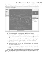
1. Draw three boxes as shown in Figure 5–2. I have labeled the boxes 1, 2, and 3 for
easy reference (you don’t have to label them). Follow the steps to see whether
you can create a similar structure in the Outliner.
2. After you draw the models, you must then identify them as groups,
components, or layers. Select Box 1, right-click, and choose Make Component.
3. From the Window menu, select Layers. The Layer dialog box will appear (Figure
5–2b). Click the + sign to add a new layer. Select Layer1, and then draw the
second box. Make sure the Visible box is selected and that the radio button is
clicked on Layer1.
4. Select the Layer0 radio button, and then create a third box. Select the box, right-
click, and choose Make Group.
Once you are all done, your Outliner should look like Figure 5–2a.
CHAPTER 5 ■ TOOLS AND TECHNIQUES TO SAVE TIME
92
a.
b.
Figure 5–2. Three boxes and the Outliner
Now you can control each of the boxes within the Outliner. The first box is grouped as a
component so you see four small squares and <Group#1>. The second and third boxes are
groups and in the Outliner are denoted by a solid square.
5. Right-click the first group in the Outliner. From the drop-down menu, select
Hide. The first box will be hidden from display. Try to hide the other boxes to
see whether you can produce a similar effect.
Download from Wow! eBook <www.wowebook.com>
CHAPTER 5 ■ TOOLS AND TECHNIQUES TO SAVE TIME
93
6. Open the Layers dialog box again, and deselect the Visible check box for Layer1
(Figure 5–3a). Notice that Box 2 disappears. It’s not actually gone. It’s still on
Layer1, but Layer1 is now hidden. To hide Boxes 1 and 3, select Layer1, and
deselect the Layer0 radio button. Now Box 2 should be visible (Figure 5–3b).
a.
b.
Figure 5–3. (a) Layer1, deselected; (b) Layer0, deselected
CHAPTER 5 ■ TOOLS AND TECHNIQUES TO SAVE TIME
94
What else can you do within the Outliner? Right-clicking each entity within the Outliner will present
you with a set of options (Figure 5–4).
Figure 5–4. Outliner options
• Entity Info allows you to choose additional options such as Layers, Hidden,
Locked, Cast Shadows, and Receive Shadows.
• Erase deletes the group or component in the model.
• Hide hides the group or component in the model.
• Lock disables the ability to move the object.
• Edit Group allows you to edit the object.
• Explode breaks your model into its individual entities.
• Make Component converts each group into a component.
We have just gone through a simple example showing how you can use the Outliner to organize and
control the visibility of your model. In the next section, you’ll look at a model that has several parts and
see how the Outliner is structured.
Using the Outliner with a Complex Model
In the previous section, you saw an example of how the Outliner looks when you are working with a very
simple model. But things can get quite complicated if the model has a lot of parts to it. In this example,
you will look at a table that has several parts so you can better understand the power of the Outliner.
Figure 5–5 shows a model of a desk; this is based on the desk that I’m using in my study. All of the parts
that make up the desk have been divided into groups and components. Rather than have you
reconstruct the model and the groups and components, you can simply download a copy of the model
from the Apress Catalog page for this book. Look in the Chapter 5 folder for a file titled Grouped table.
Open the grouped table in SketchUp. Once it’s open, you should see a model similar to the one shown in
Figure 5–5.
CHAPTER 5 ■ TOOLS AND TECHNIQUES TO SAVE TIME
95
Figure 5–5. Desk model
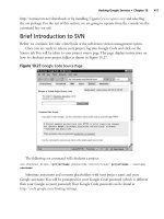
When you look at the Outliner box for this model as shown in Figure 5–6, all the components in the
model have been divided into sets: Back Support, Legs, and Horizontal Shelf. When you created a group
of the box in the previous section, you selected all the surfaces and edges that made up the box and
grouped it. With the table in Figure 5–6, you first grouped all of the individual sets into components and
then made a group of the components. The solid square indicates a group. The checkered squares
indicate components and subcomponents. You can create a component within a component to
organize your models also.
1. Click the Back Support drop-down list. What you should see are the
components that make up the back support of the table.
2. Select each component one by one within the back support, and notice those
components are highlighted on the table.
To access all the components in the model, double-click the group in the Outliner. If you want to
edit a component, then double-click it. Once within a component, you can edit it using any of the tools
in SketchUp.
CHAPTER 5 ■ TOOLS AND TECHNIQUES TO SAVE TIME
96
Figure 5–6. To the right of the model is the populated Outliner dialog box.
Hiding Groups and Components from Within the Outliner
If you were creating an instruction manual for putting together this table, then using the Outliner would
be a great option. All you would need to do is create all the parts of the table and place them into groups
or components.
1. To hide the back support of the table, right-click, and from the drop-down
menu select Hide. If you just want to hide a single component within Back
Support Tree list, right-click the component, and from the drop-down menu
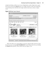
select Hide. Figure 5–7a shows the model’s back support hidden, Figure 5–7b
shows the horizontal shelf hidden, and Figure 5–7c shows the legs hidden.
If you wanted to hide a select set of components in a group, hold down the Ctrl
key, and select the components. Right-click and select Hide. Now only those
components you have selected will be hidden.
CHAPTER 5 ■ TOOLS AND TECHNIQUES TO SAVE TIME
97
a.
b.
c.
Figure 5–7 (a.) Back support hidden in the model; (b.) all of the horizontal surfaces hidden in the model;
(c.) all the legs hidden in the model
CHAPTER 5 ■ TOOLS AND TECHNIQUES TO SAVE TIME
98
This process of organization within a model can greatly reduce modeling and debugging time. It
also prepares the model for easy presentation to the customer and upload for 3D printing to Shapeways.
You can easily delete groups and components and upload only those parts that you want to develop. In
the next section, I’ll go over a few plug-ins you can utilize to increase your overall productivity during the
modeling process and before sending your model off for 3D printing.
Working with Plug-ins
A plug-in is a program that works within a software application, in this case Google SketchUp, to execute
a function. Plug-ins allow the user to enhance modeling functionality, reducing modeling time and
easing modeling frustrations.
Online you can find an assortment of plug-ins free for download. A search for the keywords
SketchUp plug-ins will present you with an abundance of plug-ins to choose from. Table 5–1 provides a
list of some of sites to visit.
Table 5–1. List of SketchUp Plug-in Sites
Website Description
www.sketchuptips.blogspot.com
This is a site called Jims SketchUp [Plugins] Blog. Here you will find
an assortment of plug-ins to download as well as resources for
Google SketchUp.
www.sketchup.google.com/
download/plug-ins.html#lightup
Google SketchUp has put together a list of plug-ins that you can
download.
www.alexschreyer.net
Alexander C. Schreyer, a PhD student at the University of
Massachusetts, has put together a great set of plug-ins. Check out
some of his other projects and video tutorials as well.
www.smustard.com/scripts/
This site offers a collection of plug-ins developed by the SketchUp
community.
In the next couple of sections, you’ll look at a few plug-ins that can assist you while you are
modeling and a few plug-ins you can use to predevelop your models even before sending them for 3D
printing: Shapes, Volume Calculator, Flattery Papercraft, and CADspan. So, let our adventure begin.
Shapes Plug-in
You will find the Shapes plug-in useful at cutting down your modeling time when you have to design
geometric shapes. Developed by @Last Software, Inc., you can use the Shapes plug-in to model boxes,
cylinders, cones, toruses, tubes, prisms, pyramids, and domes with only a few clicks of your mouse.
Before you get started and see how the model works, you will need to download the plug-in and place it
the Plugins folder of Google SketchUp. To access the Plugins folder, you need to follow a path similar to
this C:\Program Files\Google\Google SketchUp 8\Plugins. It might be different depending on the
computer you are using. You can download a copy of the plug-in from
The plug-in requires that you also
install parametric.rb and mesh_additions.rb, which are available on the site.
CHAPTER 5 ■ TOOLS AND TECHNIQUES TO SAVE TIME
99
1. Once you download and place the three files into the Plugins folder, open
SketchUp.
2. From the menu bar in Google SketchUp, select Draw ➤ Shapes. You will then
be presented with a list of shapes to choose from (Figure 5–8a).
3. When you select a shape from the list, a dialog box will appear asking for the
parameters of the model you want to create (Figure 5–8b). Enter them, and click
OK.
a. b.
Figure 5–8. (a.) List of shapes; (b.) enter the dimensions on the shape.
Figure 5–9 shows models of the shapes created with the Shapes plug-in.
Figure 5–9. A pyramid, prism, dome, tube, box, cylinder, cone, and torus—all modeled with the shape.rb
plug-in
Wasn’t that easy to model? If you were to draw these shapes from scratch using the tools in
SketchUp, it would take you a lot longer. You have saved a lot of time, so now you can work on other
parts of the model. Do you see the benefit of using a plug-in in SketchUp? Well, continue reading, and I’ll
show you couple more plug-ins I’m sure you will find useful.
CHAPTER 5 ■ TOOLS AND TECHNIQUES TO SAVE TIME
100
Volume Calculator Plug-in
Knowing the volume of a model can be very important for determining its price. As you have noticed on
Shapeways, the cost of the model depends on the amount of material you use. Using Volume Calculator
21, developed by TGI, you can easily calculate the volume and make adjustments to your models. This
tool is especially helpful when you’re working with complex volumes. Let’s go through the basic steps of
using Volume Calculator 21. You can download a copy of the plug-in from www.cad-
addict.com/2008/11/sketchup-plug-ins-volume-calculator.html.
1. Right-click, select the VolumeCalculator21.rb link, and from the drop-down list
select Save Link As. Save the file in your Google SketchUp 8 Plugins folder.
Before we dive in and do volume calculations with the plug-in, take a look at
Table 5–2, where I have done some calculations based on the formula of each
shape using the Constants in Feet values. The solution of each formula is shown
under Hand Calculation. Use the table a reference to test the calculations from
Volume Calculator 21.
Table 5–2. Volume Formulas
Shape Formula Constants in Feet Hand Calculation
Cone
25.12 cu. ft.
Cube
8 cu. ft.
Cylinder
50.24 cu. ft.
Rectangular prism
24 cu. ft.
Pyramid
2 cu. ft.
Sphere
33.49 cu. ft.
2. If you have SketchUp open from the previous example, close and reopen the
program. When SketchUp is open and you place a plug-in into the Plugins
folder, SketchUp does not detect it. Only when you open SketchUp does it
check all the files within that folder.
3. Using the Line and Push/Pull tools, create a cube that has a length, width, and
height of 2 feet. Remember to enter 2 feet; in SketchUp, you would use 2'.
4. After you draw the cube, make it into a group, or else Volume Calculator 21 will
not work. To do that, highlight the entire model, and right-click it. From the
drop-down menu, select Make Group. When you select the model now, it will
be surrounded by a blue box.
CHAPTER 5 ■ TOOLS AND TECHNIQUES TO SAVE TIME
101
5. Right-click the model, and from the drop-down menu select Volume. The
Volume Parameters dialog box will appear (Figure 5–10).
6. To calculate the volume of the cube, select Units as cu.ft, because you will be
using cubic feet. The Layer option lets you choose the layer, Hide Edges
presents you with the edges, and Color allows you to set the desired color for
the job.
Figure 5–10. Volume Parameters dialog box
7. Once all the selections have been made in the Volume Parameters dialog box,
click OK. The calculated volume of the cube should be 8 cu. ft. Compare your
results with the hand calculations in Table 5–1. If the results do not match, try
drawing the model again. This time, make sure the constants shown in Table 5–
1 are used when modeling the cube. Figure 5–11 shows the cube modeled in
SketchUp. Try to see whether you can get similar results with the other shapes
in Table 5–2.
Figure 5–11. The volume of a cube (8 cu. ft.)
Flattery Papercraft Tool
Flattery is a 3D imaging plug-in developed by Google. Flattery is a unique plug-in in that you can use it
to unfold any of your models on 2D planes. This plug-in is especially useful to 3D designers when they
CHAPTER 5 ■ TOOLS AND TECHNIQUES TO SAVE TIME
102
need quick mock-ups of their designs for demonstrations and feedback. Having a design that you can
easily print with your personal desktop printer is much easier and cheaper than sending it out for 3D
printing. On top of all that, it is free for download. You can download a copy of Flattery from
www.pumpkinpirate.info/flattery/. Unzip the download, and place the files in the Flattery folder with
your Google SketchUp Plugins folder on your computer. Once you have placed the files, remember to
reopen SketchUp for the install to take effect.
Once Flattery is installed, SketchUp will display the Flattery toolbar in SketchUp. The toolbar
consists of five buttons: Index Edges, Reunite Edges, Add Tabs, and SVG Export (Figure 5–12).
Figure 5–12. Flattery toolbar
Using the Flattery plug-in is very simple. First you will need a model to unfold. So, construct a
pyramid in SketchUp. You can choose any dimension you like.
1. Now select the entire pyramid, and click the Index Edges button.
This will create an index of all the edges in your model so that Flattery knows
which edges were connected for the Reunite Edges tool.
2. Now deselect the entire pyramid in SketchUp, and then click the Unfold Faces
button.
To deselect the model, simply click in an open space in the modeling window
before clicking the Unfold Faces button.
3. Click any surface in the model, and then click a neighboring surface.
Each surface in the model will unfold and align itself with every new surface
you click (Figure 5–13a). Continue selecting all the surfaces in the model until
all of them have been unfolded (Figure 5–13b). The next two steps are optional;
you can skip them and continue with step 7.
a. b.
Figure 5–13. Unfolding of the surfaces using the Flattery plug-in
Download from Wow! eBook <www.wowebook.com>
CHAPTER 5 ■ TOOLS AND TECHNIQUES TO SAVE TIME
103
4. With the Selector tool, double-click to enter the grouped surfaces, and select
the Reunite Edges tool.
You can use the Reunite Edges tool to readjust the location of each surface in
the model.
5. Click the surface or surfaces in the model that you want to move. Place the
cursor over one of the edges of the model, and the corresponding edge on the
selected surface will appear in red (Figure 5–14a).
6. Click the edge, and the surface will attach to the selected edge (Figure 5–14b).
This is a great tool to use especially when you have a complex model with many surfaces.
a. b.
Figure 5–14. Using the Reunite Edges tool to move surfaces
Next you’ll add tabs to the surfaces.
7. Select the Tab tool, and place the cursor over an edge.
Its corresponding edge will appear red.
8. Click the edge once, and drag the mouse to view an outline of the tab being
created (Figure 5–15a). Click again once you are happy with the outline to
create the tab.
a. b.
Figure 5–15. Creating the tabs for your model
CHAPTER 5 ■ TOOLS AND TECHNIQUES TO SAVE TIME
104
9. Continue the process to draw in all the tabs in the model.
All that is left for you to do is export the model for printing.
10. Select the SVG Export tool, and save an export of the file onto your computer.
You are all done; now, using a photo-editing program such as Inkscape or Photoshop, you can easily
print the design onto paper to be cut out and fold. As mentioned earlier, you can unfold your 3D models
and print them effortlessly, saving time and money. This is a great way to test your design before sending
it off for 3D printing.
CADspan Plug-in
CADspan is great for converting your models from SketchUp files with the .skp extension to an STL file,
especially if you need to upload your file for 3D printing to another service other than Shapeways. In
Chapter 12, I discuss a few companies that use STL files for 3D printing their models. On top of being a
file converter, CADspan can be used to debug your models for any problems. In addition to converting
models to STL files, the plug-in has features such as Resurface, Layerize, Unsmooth Model, Preview
Style, Import Geometry, and Export to Raw STL (Figure 5–16).
Figure 5–16. CADspan dialog box in SketchUp
So, what does each tool do in SketchUp?
• Resurface creates a mesh around the model to convert the model into a solid
structure.
• The Layerize tool allows you to select the entire model or surfaces and place them
on a layer.
• The Unsmooth tool is used to remove smooth surfaces from the model.
• Preview Style highlights all the problematic areas in the model with a red color.
• Import Geometry allows you to import STL files for checking before uploading to
CADspan.
Before you see how you can use CADspan in assisting in debugging and converting your models,
you will first need to download a copy of the CADspan plug-in. To download your own copy, visit
www.cadspan.com and on right of the web site click CADspan Plugin (Figure 5–17). Then on the next page,
click to download the plug-in. This will direct you to the download page where you can select the version
of CADspan to download. On a Windows computer, click Windows: Google SketchUp 8 to download the
plug-in onto your computer.
Unlike other plug-ins you have installed, this plug-in downloads as an executable file. Double-click
the executable file, and follow the on-screen instructions to install the plug-in.
CHAPTER 5 ■ TOOLS AND TECHNIQUES TO SAVE TIME
105
Figure 5–17. CADspan web site
After installation, open Google SketchUp. The plug-in will appear on your Getting Started toolbar.
Understanding the STL Format
Now that the plug-in is installed, you’ll take the lighthouse model you designed in Chapter 4 and convert
it into an STL file. But before doing that, let’s briefly review what an STL file is.
The .stl file is a common 3D printing file format that you will encounter as you continue 3D
modeling beyond just this book. STL files store triangulated information of 3D surfaces. Each surface is
broken down into smaller triangles that are described by three points and a perpendicular direction. You
can think of describing a 3D surface with a mesh of triangles. It is this mesh that describes the shape and
form of the model. Think of the Eiffel Tower in Paris, France. It is built with a mesh of triangles.
An STL file is described by facets. Each facet consists of a triangle and a norm that is perpendicular
to the triangular surface (Figure 5–18). Each of the vertices of the triangle is described by three data
points
, , , and the norm is described by , , . In total, there are 12 points that describe a
single facet. Following the right-hand rule, with your thumb facing norm and fingers pointing in the
counterclockwise direction, the vertices are all positive values.
CHAPTER 5 ■ TOOLS AND TECHNIQUES TO SAVE TIME
106
Figure 5–18. Twelve points that describe a single facet
You will encounter two types of STL file formats: ASCII and binary. Although ASCII STL files are
more popular when testing or debugging a system, they are very big and impractical to use. Binary STL
files are much more commonly used and far more practical than ASCII.
Converting to an STL File
Now you’ll take the lighthouse model that you designed in Chapter 4 and convert it into an STL file.
1. Open the Lighthouse.skp file from Chapter 4, and select Preview Style.
This will highlight the model in either of two colors, brown or red. If any of the
outer surfaces of the model are red, then the surface must be reversed. In that
case, reverse the surface so that you see brown on the outside. If you see a red
surface facing outside, then one or more of your surfaces is facing outward.
During 3D printing, this will appear as an error, and Shapeways will not upload
your model. Right-click, and select Reverse Faces from the drop-down list to
reverse all the red faces. You should now have a model like Figure 5–19.
CHAPTER 5 ■ TOOLS AND TECHNIQUES TO SAVE TIME
107
Figure 5–19. Lighthouse model to preview style
2. Now select Resurface, and the CADspan Resurfacer dialog box will appear
(Figure 5–20a).
If this is your first time opening the CADspan Resurfacer dialog box, then you
will need to register for a user name and password. Click Register to create your
user name and password on CADspan.
CHAPTER 5 ■ TOOLS AND TECHNIQUES TO SAVE TIME
108
a. b.
Figure 5–20. CADspan Resurfacer
Once logged in, the CADspan Resurfacer menu options appear (Figure 5–20b).
1. Within Resurfacer are six tabs; select the CADspan tab. Under CADspan are File
Details, Processing Options, and Status. There is a 7,500 polygon upload limit
for the free version of CADspan. In the center of the CADspan window, you will
see two sliders: Gap Fill and Resolution. Gap Fill is used to fill in holes in the
model. Higher settings are recommended for models with many holes. Lower
settings are recommended for models with fewer holes. Too high or too low of a
setting could result in webbing or could create leaks in the model. Higher-
resolution models will produce better-looking .stl files. For this example, you
will stay with the default settings.
2. Click Upload to upload the model to the CADspan server, and then select
Process. CADspan then converts the design to an .stl file format. The process
takes a few seconds to a few hours depending on the complexity of the model.
Once processing is complete, the progress bar will read Complete. The
lighthouse model uploaded has 474 polygons/triangles. Then click Download.
3. The File Download box will appear (Figure 5–21). Click Save to save the zip file
on your computer. Unzip the file after download to access its contents.
CHAPTER 5 ■ TOOLS AND TECHNIQUES TO SAVE TIME
109
Figure 5–21. File Download dialog box
Within the ZIP file will be the STL file. You are now ready to upload the file to Shapeways or any other 3D
printing service that accepts STL files. Check out Chapter 12 where I go over a couple of other 3D
printing services that will accept STL file uploads.
Summary
In this chapter, you learned about the Outliner and how you can use it to organize models within
SketchUp. You also learned about groups, components, and layers and saw how each can be used to
organize a model and speed up modeling time. Then you explored a few plug-ins and saw how they can
be a great resource when working with models in SketchUp. In the next chapter, you will learn all about
modeling curved shapes and applying groups and components to model a sundial.
CHAPTER 5 ■ TOOLS AND TECHNIQUES TO SAVE TIME
110
C H A P T E R 6
■ ■ ■
111
Breaking the Barrier
In this chapter, you’ll design two models. The first model you will design is a chess pawn where you will
learn the techniques of modeling objects with curved surfaces for 3D printing. In the second half of the
chapter, you’ll switch gears and learn how to design a sundial. By designing the sundial, you will learn
how to use groups, components, and shadow settings when developing and testing the model.
Designing Curved Models
You must be wondering by now how on Earth you could model that jar, cup, bottle, lamp shade, or
ceiling fixture in your house using SketchUp. So far, you have modeled objects that have flat surfaces.
Well, there is a way to design objects that have curved surfaces in SketchUp. The tools you will need to
use are Follow Me and Arc. In this section, I’ll demonstrate the steps of designing a chess pawn using
both tools. If you were designing a lamp shade or bottle, similar methods would apply.
Creating the Pawn Template
To construct the pawn, you first have to change the view of the modeling window. From the menu bar,
select Camera ➤ Standard Views ➤ Front (Figure 6–1). Once in the front view, you are ready to start
modeling.
The pawn piece that you will be designing is based on the original Staunton chess piece. From
rough measurements, the pawn has a width of 14mm and a height of 28mm. Since you already know
what you are modeling, I have skipped the steps of developing a mind map and sketches of the model.
I recommend you develop a few sketches of your model if you decide to model something different.
CHAPTER 6 ■ BREAKING THE BARRIER
112
Figure 6–1. Changing the view of your modeling window
Starting from the center of the axis, follow these steps:
1. Select the Rectangle tool, click the axis, and then type 7mm, 28mm.
You will create only half the model and then copy the rest to the other half
(Figure 6–2a).
2. Using the Tape Measure tool, create guidelines from the bottom of the box at
2mm, 6mm, 7mm, 8mm, 19mm, 20mm, and 21mm in height (Figure 6–2b).
3. Once the guidelines are in place, draw the outer edge that defines the pawn
(Figure 6–2c).
You can use the template in Figure 6–2c to guide you in constructing the edges
of the pawn piece or observe an actual Staunton chess pawn online.
Download from Wow! eBook <www.wowebook.com>
CHAPTER 6 ■ BREAKING THE BARRIER
113
a. b. c.
Figure 6–2. Constructing the pawn template in SketchUp
4. Select the Arc tool, and then click the bottom-right corner and then the first
guideline from the bottom at 2mm. Drag the cursor outward to create an arc.
Click once more to lock the arc in place.
Continue the same process to create all the other arcs that define the pawn, as
shown in Figure 6–2c. Once you have drawn the entire outer edge of the model,
make sure there are no broken lines.
5. Select the surface on the left side of the arc.
If the left half is highlighted with blue dots, then there are no broken edges in
the model. If not, then the line must be broken some place along the curved
path you created. In this case, you need to zoom into the curve. Select the Zoom
tool, and press and hold the left mouse key in the modeling window. Move the
cursor left to right to zoom in and out of the model.
6. Once the broken lines are fixed, select and delete all the edges and surfaces to
the right of the model.
You do not need the guidelines either. You can delete them or hide them in case you need them
later. Click each guideline, and from the drop-down menu, select Hide. All you should be left with now is
an outline of half a pawn (Figure 6–3, without the circle at the bottom).