adobe InDesign CS5 Bible for dummies PHẦN 4 docx
Bạn đang xem bản rút gọn của tài liệu. Xem và tải ngay bản đầy đủ của tài liệu tại đây (1.47 MB, 46 trang )
Part III
Object Essentials
12_614495-pp03.indd 11712_614495-pp03.indd 117 4/2/10 1:28 PM4/2/10 1:28 PM
In this part . . .
T
he rubber really hits the road when you’ve got your
basic layout structure in place. Now you can focus on
the meat of your documents: the objects that contain your
text and graphics. It’s amazing all the objects you can cre-
ate — from simple rectangles to complex curves. And it’s
equally amazing all the things you can do to objects, such
as rotate them, color and align them, and apply special
effects, such as drop shadows and directional feathers.
And you can even save a lot of these settings so that you
can apply them consistently to other objects later — a
real timesaver that also ensures quality results.
Note that you can apply most of these effects to objects
whether or not they already contain their graphics and
text — so if you’re a really structured kind of person,
you’ll probably create your basic object containers first,
apply your effects to them, and then bring in the text and
graphics. But if you’re more free-form in your approach,
you’ll likely bring in all your text and graphics, and then
start arranging the objects that contain them to produce
your final layout. That’s fine. Either way, you just apply
the techniques in this part while doing so.
12_614495-pp03.indd 11812_614495-pp03.indd 118 4/2/10 1:28 PM4/2/10 1:28 PM
Chapter 7
Adding Essential Elements
In This Chapter
▶ Creating frames and shapes
▶ Making lines and paths
▶ Working with text shapes and paths
▶ Using strokes
T
he fundamental components of any layout are its objects. This chapter
explains how to create these building blocks: frames, shapes, lines, and
paths, as well as the strokes you apply to them.
Working with Frames and Shapes
An object is a container that can (but doesn’t have to) hold text or graph-
ics, as well as display attributes such as color, strokes, and gradients. When
an object contains an imported graphic or text, or if an object is created as
a placeholder for a graphic or text, it’s referred to as a frame in InDesign.
Otherwise, it’s called a shape.
The difference between frames and shapes is artificial. Because a shape can
easily become a frame simply by placing text or graphics into it, it’s easiest to
think of shapes and frames as the same thing. I tend to use the word “frame”
to mean either frames or shapes.
Designing pages in InDesign is largely a matter of creating and modifying
frames and shapes, as well as modifying the text and graphics that the frames
contain.
Creating frames and shapes
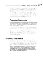
As Figure 7-1 shows, the Tools panel contains several tools for creating both
shapes and frames:
13_614495-ch07.indd 11913_614495-ch07.indd 119 4/2/10 1:27 PM4/2/10 1:27 PM
120
Part III: Object Essentials
✓ The Rectangle, Ellipse, and Polygon shape tools: The Ellipse and
Polygon tools are available through the pop-up menu that appears if you
click and hold on the Rectangle tool.
✓ The Rectangle Frame, Ellipse Frame, and Polygon Frame tools: The
Ellipse Frame and Polygon Frame tools are available through the pop-up
menu that appears if you click and hold on the Rectangle Frame tool.
✓ The Type tool: You can use this tool to create rectangular text frames in
addition to letting you work with text.
Figure 7-1:
The
frame- and
shape-
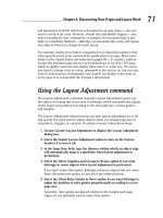
creating
tools in the
Tools panel,
as well as
the other
tools to
create and
manipulate
lines and
paths.
Type tool
Pencil tool
Line tool
Here’s how to create a frame (or shape):
1. Select the desired tool from the Tools panel.
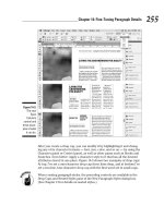
2. Optionally, set up the polygon’s number of sides and the depth of its
spikes.
To do so, double-click the tool you’re using (Polygon or Polygon Frame)
so the Polygon Settings dialog box appears. Figure 7-2 shows that dialog
box and example starburst. Adjust the number of sides and their depth
(the Star Inset field) as desired, and then click OK. If you don’t adjust
the polygon’s settings and instead just begin drawing on as in the next
steps, InDesign will use the last-used settings for the selected tool.
3. Move the mouse pointer anywhere within the currently displayed
page or on the pasteboard.
13_614495-ch07.indd 12013_614495-ch07.indd 120 4/2/10 1:27 PM4/2/10 1:27 PM
121
Chapter 7: Adding Essential Elements
Figure 7-2:
The Polygon
Settings
dialog box
lets you
specify the
number of
sides your
polygons
will have.
4. Click and drag in any direction.
As you drag, a cross-hair pointer appears in the corner opposite your
starting point; a colored rectangle indicates the boundary of the frame.
(The color is blue for objects on the default layer; objects on other
layers have those layers’ respective colors. See Chapter 4 for more on
layers.) You can look at the width and height values displayed in the
Control panel or the Transform panel as you drag to help you get the
size you want. Holding down the Shift key as you drag limits the tool to
creating a frame or shape within a square bounding box.
5. When the frame is the size and shape you want, release the mouse
button.
Pretty easy, huh? At this point, you can begin typing in the frame, paste text
or a graphic into it, or import a text or a graphics file, as Chapters 10 and 16
explain.
If you create a text frame with the Type tool, be sure not to click in an existing
text frame when your intention is to create a new one. If you click within an
existing frame when the Type tool is selected, the flashing cursor appears, and
InDesign thinks you want to type text.
InDesign CS5 lets you create multiple frames at the same time, using a new
capability that Adobe calls gridified frame creation. While dragging the mouse
to create a frame, press the → key to add an additional frame horizontally
(a new “column”) or the ↑ key to add an additional frame vertically (a new
“row”). Each time you press → or ↑, you add another column or row of frames.
Press ← to delete a column and ↓ to delete a row.
13_614495-ch07.indd 12113_614495-ch07.indd 121 4/2/10 1:27 PM4/2/10 1:27 PM
122
Part III: Object Essentials
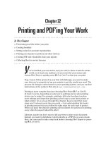
As Figure 7-3 shows, when you release the mouse, InDesign creates a grid of
frames, all with the same shape and size. If you’re creating text frames, all
the text frames in such a grid are automatically threaded for text flow. The
thread follows the order you dragged the mouse when creating the frame: If
you dragged from upper left to lower right, the thread starts at the leftmost
text frame in the top row and continues to each adjacent text frame, then
continues at the leftmost text frame in the next row, and so on.
Figure 7-3:
The gridified
frame-creation
capability
lets you
create
multiple
frames at
once.
When any of the frame-creation tools is selected, you can create as many
new frames as you want. Simply keep clicking, dragging, and releasing. After
you create a graphics frame, you can modify it (without changing tools) by
adding a border or a colored background or by applying any of the effects —
such as rotation, shear, and scale — in the Control panel. You can also move
or resize a graphics frame, but you have to switch to the Selection tool or the
Direct Selection tool to do so. Chapter 8 explains how to resize, move, delete,
and otherwise manipulate frames and other objects.
Reshaping frames and shapes
Sometimes, a frame or shape needs to be more than resized or moved. It
needs to be reshaped. InDesign makes it easy to change an object’s shape:
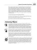
✓ The simplest way is to select an object with the Direct Selection tool
and then drag any of the handles or frame edges. Notice how the frame’s
shape actually changes, as shown in Figure 7-4.
13_614495-ch07.indd 12213_614495-ch07.indd 122 4/2/10 1:27 PM4/2/10 1:27 PM
123
Chapter 7: Adding Essential Elements
✓ To change a shape more radically, choose the desired shape from
Object➪Convert Shape’s submenu. Your choices are Rectangle,
Rounded Rectangle, Beveled Rectangle, Inverse Rounded Rectangle,
Ellipse, Triangle, Polygon, Line, and Orthogonal Line. (Note that if you
choose Polygon, InDesign will use whatever the last polygon settings
were, which you can see by double-clicking the Polygon or Polygon
Frame tool. Also, if you try to convert a text frame into a line, InDesign
will abort the action, telling you it can’t do the conversion.)
✓ You can manually edit a shape by adding or removing anchor points —
the points in a shape’s edges that you can adjust, as described in the
next section.
If you’re working with frames that contain graphics, InDesign CS5 has a quick
way to switch from the Selection tool to the Direct Selection tool: Just click the
content grabber (the doughnut shape at the frame’s center when you hover
the mouse over the frame). If the content grabber does not display, turn it
on by choosing View➪Extras➪Show Content Grabber. Note that in InDesign
CS5 double-clicking a frame no longer switches between the Selection and
Direction Selection tools.
Figure 7-4:
After
creating a
frame (left),
reshape it
by drag-
ging its
handle with
the Direct
Selection
tool (right).
Creating Lines and Paths
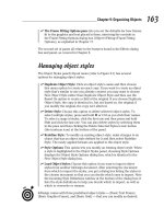
When you’re drawing the old-fashioned way, with pen and paper, you typi-
cally use one tool to draw straight lines, curved lines, and free-form objects.
InDesign is less flexible, using different tools for different kinds of lines.
InDesign lets you create straight lines with the Line tool and zigzag lines,
13_614495-ch07.indd 12313_614495-ch07.indd 123 4/2/10 1:27 PM4/2/10 1:27 PM
124
Part III: Object Essentials
curved lines, and free-form shapes with the Pen and Type on a Path tools.
(Those nonstraight lines and free-form shapes are called paths in InDesign.)
Figure 7-1, earlier in this chapter, shows these tools on the Tools panel.
Drawing a straight line
Although not as flashy or versatile as shapes and paths, lines can serve many
useful purposes in well-designed pages. For example, you can use plain ol’
vertical rules to separate columns of text in a multicolumn page or the rows
and columns of data in a table. Dashed lines are useful for indicating folds
and cut lines on brochures and coupons. And lines with arrowheads are
handy if you have to create a map or a technical illustration.
Follow these steps to draw a simple, straight line:
1. Select the Line tool (or press \).
2. Move the pointer anywhere within the currently displayed page or on
the pasteboard.
3. Click and drag the mouse in any direction.
As you drag, a thin, blue line appears from the point where you first
clicked to the current position of the cross-hair pointer. Holding down
the Shift key as you drag constrains the line to a horizontal, vertical, or
45-degree diagonal line.
4. When the line is the length and angle you want, release the mouse
button.
Don’t worry too much about being precise when you create a line. You
can always go back later and fine-tune it.
When you release the mouse button after creating a line, the line is active.
As illustrated in Figure 7-5, if the Selection tool was previously selected, the
line appears within a rectangular bounding box, which contains eight resiz-
ing handles. If the Direct Selection tool was previously selected, moveable
anchor points appear at the ends of the line. In either case, you have to
choose the right tool if you want to change the shape or size of the bounding
box or the line:
✓ The Selection tool lets you change the shape of the line’s bounding box
(which also changes the angle and length of the line) by dragging any of
the resizing handles.
✓ The Direct Selection tool lets you change the length and angle of the line
itself by moving anchor points on the frame.
As long as the Line tool is selected, you can create as many new lines as you
want. Simply keep clicking, dragging, and releasing.
13_614495-ch07.indd 12413_614495-ch07.indd 124 4/2/10 1:27 PM4/2/10 1:27 PM
125
Chapter 7: Adding Essential Elements
Figure 7-5:
A line
selected
with the
Selection
tool (left)
and the
Direct
Selection
tool (right).
When you create a line, it takes on the characteristics specified in the Stroke
panel (Window➪Stroke [Ô+F10 or Ctrl+F10]), covered in the “Applying
strokes” section later in this chapter. When you first open a document, the
default line width is 1 point. If you want to change the appearance of your
lines, double-click the Line tool and adjust the Weight setting in the Stroke
panel that appears. If you make this adjustment when no document is open,
all new documents will use the new line settings.
Understanding paths
Paths are a lot more complex than lines, so you need to understand some of
the theory behind paths so that you can create and manipulate them more
easily.
Every object you create with InDesign’s object-creation tools is a path.
Regardless of the tool you use to create a path, you can change its appear-
ance by modifying any of four properties that all paths share:
✓ Closure: A path is either open or closed. Straight lines created with
the Line tool and curved and zigzag lines created with the Pen tool
are examples of open paths. Basic shapes created with the Ellipse,
Rectangle, and Polygon tools and free-form shapes created with the Pen
and Pencil tools are examples of closed shapes. A closed free-form shape
is an uninterrupted path with no end points.
✓ Stroke: If you want to make a path visible, you can apply a stroke to it
by selecting it with a selection tool, entering a Weight value in the Stroke
panel (Window➪Stroke [Ô+F10 or Ctrl+F10]), and selecting a color from
the Swatches panel (see Chapter 6). (An unselected, unstroked path isn’t
visible.)
13_614495-ch07.indd 12513_614495-ch07.indd 125 4/2/10 1:27 PM4/2/10 1:27 PM
126
Part III: Object Essentials
✓ Fill: A color, color tint, or gradient applied to the background of a path
is called a fill. You apply fills by using the Swatches panel.
✓ Contents: You can place a text file or a graphics file in any path except
a straight line. When a path holds text or a graphic, the path functions
as a frame. Although InDesign can place text or graphics in an open
path, placing text and pictures in closed paths is far more common than
placing them in open paths. In addition to putting text inside paths, you
can also have text on the path itself, following its shape, as Chapter 17
explains.
No matter how simple or complicated, all paths are made up of the same
components. Figure 7-6 shows the parts that make up a path:
Figure 7-6:
Anchor
points
between
line
segments
can be
corner (top)
or smooth
(bottom).
End point
Anchor point
Segment
End point
Anchor point
Segment
Anchor point
End point
✓ A path contains one or more straight or curved segments.
✓ An anchor point is located at each end of every segment. The anchor
points at the ends of a closed path are called end points. When you
create a path of any kind, anchor points are automatically placed at the
end of each segment. After you create a path, you can move, add, delete,
and change the direction of corner points.
✓ InDesign has two kinds of anchor points: smooth points and corner points.
A smooth point connects two adjoining curved segments in a continu-
ous, flowing curve. At a corner point, adjoining segments — straight or
13_614495-ch07.indd 12613_614495-ch07.indd 126 4/2/10 1:27 PM4/2/10 1:27 PM
127
Chapter 7: Adding Essential Elements
curved — meet at an angle. The corners of a rectangular path are the
most common corner points.
✓ A direction line runs through each anchor point and has a handle at both
ends. You can control the curve that passes through an anchor point by
dragging a direction line’s handles, as I explain a little later on.
Drawing your own paths
Even if you’re an artistic master with a piece of charcoal or a No. 2 pencil,
you need to practice with the Pen tool for a while before your drawing skills
kick in. The good news is that after you get comfortable using the Pen tool,
you can draw any shape you can imagine. (Of course, if you can’t draw very
well in the first place, using the Pen tool won’t magically transform you into
a master illustrator!) If creating a free-form path is new terrain for you, start
simply and proceed slowly.
When creating paths, use as few anchor points as possible. As you become
more comfortable creating free-form paths, you should find yourself using
fewer anchor points to create paths.
For an easy way to draw free-form shapes, use the Pencil tool. This tool simply
traces the movement of your mouse (or pen tablet) as you move it, much like
a pencil works on paper. Although not as exact as the Pen tool, the Pencil tool
creates Bézier curves that you can later edit. Note that the Pencil tool is not
meant for creating straight lines — unless you’re capable of drawing perfectly
straight lines by hand, that is.
Straight and zigzag lines
Follow these steps to draw lines with straight segments, such as a zigzag:
1. Select the Pen tool.
2. Move the Pen pointer to where you want to start your line segment.
3. Click and release the mouse button.
Make sure that you don’t drag before you release the mouse button.
An anchor point appears; it looks like a small, filled-in square.
4. Move the Pen pointer to where you want to place the next anchor
point.
5. Click and release the mouse button.
InDesign draws a straight line between the two anchor points. The first
anchor point changes to a hollow square, and the second anchor point
is filled in, which indicates that it’s the active anchor point.
13_614495-ch07.indd 12713_614495-ch07.indd 127 4/2/10 1:27 PM4/2/10 1:27 PM
128
Part III: Object Essentials
6. Repeat Steps 4 and 5 for each additional anchor point.
To reposition an anchor point after you click the mouse button but
before you release it, hold down the spacebar and drag. Otherwise, you
need to select it with the Direct Selection tool after you finish drawing
the line and then click and drag it to its new location.
7. To complete the path, press Enter or Return, Ô+click or Ctrl+click
elsewhere on the page, or simply choose another tool.
If you Ô+click or Ctrl+click, the Pen tool remains active, so you can con-
tinue creating new paths.
Curved lines
Knowing how to draw zigzag lines is fine (see preceding section), but chances
are, you want to draw curved shapes as well. The basic process is similar
to drawing straight segments, but drawing curved paths (technically, Bézier
paths) is more complicated and will take you some time to get the hang of.
If you want to draw a continuously curvy path that contains no corner points
and no straight segments, you should create only smooth points as you draw.
Here’s how:
1. Select the Pen tool.
2. Move the Pen pointer to where you want to start the curve segment.
3. Click and hold down the mouse button.
The arrowhead pointer appears.
4. Drag the mouse in the direction of the next point you intend to create,
and then release the mouse button.
As you drag, the anchor point, its direction line, and the direction line’s
two handles are displayed, as shown in Figure 7-7.
Figure 7-7:
To create
a smooth
point, click
and hold the
mouse and
drag in the
direction
of the next
point.
Anchor point being
End point
Direction line
Direction line handle
13_614495-ch07.indd 12813_614495-ch07.indd 128 4/2/10 1:27 PM4/2/10 1:27 PM
129
Chapter 7: Adding Essential Elements
If you hold down the Shift key as you drag, the angle of the direction line
is limited to increments of 45 degrees.
5. Move the Pen pointer to where you want to place the next anchor
point — and end the first segment — and then drag the mouse.
If you drag in roughly the same direction as the direction line of the pre-
ceding point, you create an S-shaped curve; if you drag in the opposite
direction, you create a C-shaped curve.
6. When the curve between the two anchor points looks how you want it
to look, release the mouse button.
Alternatively, when you want to connect curved segments to corner
points (shown in Figure 7-8), move the Pen pointer to where you want
to place the next anchor point — and end the first segment — and then
press and hold Option or Alt as you click and drag the mouse. As you
drag, the anchor point’s handle moves, and the direction line changes
from a straight line to two independent segments. The angle of the direc-
tion line segment that you create when you drag the handle determines
the slope of the next segment.
7. Repeat Steps 5 and 6 for each additional desired curved segment.
8. To complete the path, Ô+click or Ctrl+click elsewhere on the page or
simply choose another tool.
If you Ô+click or Ctrl+click, the Pen tool remains active, so you can
create new paths.
You can also complete the path by clicking the first point you created,
which creates a closed path.
How smooth and corner points work
Bézier paths have two kinds of points to join
segments: corner and smooth.
The two segments that form a smooth point’s
direction line work together as a single, straight
line. When you move a handle, the line acts like
a teeter-totter; the opposite handle moves in
the opposite direction. If you shorten one of
the segments, the length of the other segment
doesn’t change. The angle and length of direc-
tion lines determine the shape of the segments
with which they’re associated.
A corner point that connects two curved seg-
ments has two direction lines: a corner point
that connects two straight segments has no
direction lines; and a corner point that connects
a straight and curved segment has one direc-
tion line. If you drag a corner point’s direction
line, the other direction line, if there is one, isn’t
affected.
13_614495-ch07.indd 12913_614495-ch07.indd 129 4/2/10 1:27 PM4/2/10 1:27 PM
130
Part III: Object Essentials
If you create two open paths that you want to join together into one path, you
can do so in InDesign by selecting the two paths and then choosing
Object➪Paths➪Join. InDesign usually joins the two closest points with a
straight line, but it sometimes joins the last point of the first path and the first
point of the second path.
Do note that if you try to join a text path with a regular path, the text will be
deleted if it’s the second path selected. If you join two text paths, the second
path’s text will also be deleted. Finally, if you select three or more paths and
choose Object➪Paths➪Join, nothing will happen.
Figure 7-8:
Three
corner
points join
four curved
segments.
Closed paths
A closed path is simply a path that ends where it began. When it comes to
creating closed paths with the Pen tool, the process is exactly the same as
for creating open paths (such as curved lines and zigzag lines), as explained
in the “Curved lines” and “Straight and zigzag lines” sections, earlier in this
chapter, with one difference at the end:
✓ To create a straight segment between the end point and the last anchor
point you created, click and release the mouse button.
✓ To create a curved segment, click and drag the mouse in the direction of
the last anchor point you created and then release the mouse button.
Just like an open path, a closed path can contain straight and/or curved seg-
ments and smooth and/or corner anchor points. All the techniques explained
earlier in this chapter for drawing lines with curved and straight segments
and smooth and corner points apply when you draw closed paths.
You can also, of course, edit and adjust your curves in InDesign, but doing
so requires some more expertise with drawing tools such as those in Adobe
Illustrator and is beyond the scope of this book. Check out Illustrator CS5 For
13_614495-ch07.indd 13013_614495-ch07.indd 130 4/2/10 1:27 PM4/2/10 1:27 PM
131
Chapter 7: Adding Essential Elements
Dummies by Ted Alspach or Adobe InDesign CS5 Bible by Galen Gruman (both
by Wiley Publishing) for more details.
Blurring the Lines between
Text and Graphics
InDesign lets you create shapes out of text, as well as make text run along a
path — blurring the boundary between text and graphics.
Converting text to shapes
If you want to use the shape of a letter or the combined shapes of several
letters as a frame for text or a graphic, you could test your skill with the Pen
tool and create the letter shape(s) yourself. But getting hand-drawn charac-
ters to look just the way you want them to can take lots of time. A quicker
solution is to use the Create Outlines command to convert text characters
into editable outlines. The Create Outlines command is particularly useful if
you want to hand-tweak the shapes of characters, particularly at display font
sizes, or place text or a graphic within character shapes.
If all you need to do is apply a stroke or fill to characters within text, you don’t
have to convert the characters into outlines. Instead, simply highlight the char-
acters and use the Stroke panel (Window➪Stroke [Ô+F10 or Ctrl+F10]) and
Swatches panel (Window➪Color➪Swatches [F5]) to change their appearance.
This way, you can still edit the text. (Strokes are covered later in this chapter.)
When you use the Create Outlines command, you have the choice of creating
an inline compound path that replaces the original text or an independent
compound path that’s placed directly on top of the original letters in its own
frame. If you want the text outlines to flow with the surrounding text, create
an inline compound path. If you want to use the outlines elsewhere, create an
independent compound path.
To convert text into outlines, follow these steps:
1. Use the Type tool to highlight the characters you want to convert into
outlines.
Generally, this feature works best with large font sizes.
2. Choose Type➪Create Outlines (Shift+Ô+O or Ctrl+Shift+O — that’s the
letter O, not a zero).
If you hold down the Option or Alt key when you choose Create Outlines
(or if you press Shift+Option+Ô+O or Ctrl+Alt+Shift+O), a compound
13_614495-ch07.indd 13113_614495-ch07.indd 131 4/2/10 1:27 PM4/2/10 1:27 PM
132
Part III: Object Essentials
path is created and placed in front of the text. In this case, you can use
either of the selection tools to move the resulting compound path. If
you don’t hold down Option or Alt when you choose Create Outlines, an
inline compound path is created. This object replaces the original text
and flows with the surrounding text.
After you create text outlines, you can modify the paths the same as you
can modify hand-drawn paths. You can also use the transformation tools,
the Control panel (Window➪Control [Option+Ô+6 or Ctrl+Alt+6]), and the
Transform panel (Window➪Transform) to change the appearance of text out-
lines. But you can’t edit text after converting it to outlines.
Additionally, you can use the Place command (File➪Place [Ô+D or Ctrl+D])
or the Paste Into command (Edit➪Paste Into [Option+Ô+V or Ctrl+Alt+V])
to import text or a graphic into the frames created by converting text to
graphics.
Making text follow a path
InDesign lets you have text follow any open or closed path, such as a line or
frame. Simply select the path or shape with the Type on a Path tool, which
is available from the Type tool’s pop-up menu. Now start typing (or paste or
place) your text.
After you enter the text and format it with font, size, color, and so on, you
can apply special effects to it using the Type on a Path Options dialog box,
accessed by choosing Type➪Type on a Path➪Options.
You can also double-click the Type on a Path tool to open the Type on a Path
Options dialog box.
Figure 7-9 shows the dialog box and several examples of its formatting. In the
dialog box:
✓ Use the Effect pop-up menu to choose a visual effect.
✓ Use the Align pop-up menu to choose what part of the text is aligned
(baseline, center, ascender, or descender).
✓ Use the To Path pop-up menu to choose whether to align to the center,
bottom, or top of the path.
✓ Flip the text by selecting the Flip option.
✓ Change the text’s spacing by entering a value in the Spacing field (posi-
tive numbers space out the text, while negative ones contract it).
13_614495-ch07.indd 13213_614495-ch07.indd 132 4/2/10 1:27 PM4/2/10 1:27 PM
133
Chapter 7: Adding Essential Elements
Figure 7-9:
The Type
on a Path
Options
dialog
box and
example
text paths.
Applying Strokes
All objects have a stroke with a width of 0 built in, so you never have to add
strokes. But to use them, you need to modify them so that they have some
thickness onto which you can apply attributes, such as colors and gradients.
Setting stroke appearance
The Stroke panel is where you give the stroke its width, as well as apply the
type of stroke and other attributes. Follow these steps:
1. Select either of the selection tools and click the object whose stroke
you want to modify, or select the Type tool and select the text whose
stroke you want to modify.
2. If the Stroke panel isn’t displayed, show it by choosing
Window➪Stroke (Ô+F10 or Ctrl+F10).
Figure 7-10 shows the panel.
Figure 7-10:
The Stroke
panel (left)
and the
Swatches
panel (right).
13_614495-ch07.indd 13313_614495-ch07.indd 133 4/2/10 1:27 PM4/2/10 1:27 PM
134
Part III: Object Essentials
3. To change the width of the stroke, enter a new value in the Weight
field.
You can also change the Weight value by choosing a new value from the
field’s pop-up menu or by clicking the up and down arrows. (Each click
increases or decreases the stroke by 1 point.)
4. Set the Miter Limit.
The default of 4 is fine for almost all frames. You rarely need to use this
feature, so don’t worry about it.
5. Click any of the three Cap iconic buttons to specify how dashes will
look if you create a dashed stroke (covered in Step 9).
Experiment with them in your objects to see which looks best for your
situation. (This option is not available for text.)
6. Click any of the three Join iconic buttons to specify how corners are
handled.
Again, experiment with these buttons to see what works best for you.
7. Choose an Align Stroke option.
The default is the first button, Align Stroke to Center, which has the
stroke straddle the frame. You can also choose Align Stroke to Inside,
which places the entire thickness inside the frame boundary, or Align
Stroke to Outside, which places the entire thickness outside the frame
boundary. (The Align Stroke to Inside button is not available for text.)
8. Unless you’re working with text, you can choose end points for your
strokes by using the Start and End pop-up menus.
End points appear only on lines and other open paths, not on rectangles,
ellipses, or other closed-loop shapes.
9. To create a dashed line instead of a solid line, choose an option from
the Type pop-up menu.
These options are also available from the Control panel. Note they are
not available for text selections.
Choose from 18 types of predefined dashes and stripes. The Gap Color
and Gap Tint fields at the bottom of the Stroke panel also become active,
to let you choose a color and tint for the gaps in dashes and stripes.
After you have a visible stroke, you want to color it. Here’s how:
1. Select either of the selection tools and click the frame to which you
want to add a stroke, or select the stroked text with the Type tool.
2. Click the Stroke iconic button in the Swatches panel, Control panel, or
Tools panel.
13_614495-ch07.indd 13413_614495-ch07.indd 134 4/2/10 1:27 PM4/2/10 1:27 PM
135
Chapter 7: Adding Essential Elements
3. Click a color, tint, or gradient from the Swatches panel; or click one
of the boxes at the bottom of the Tools panel, which let you use (from
left to right) the last-selected color, last-selected gradient, or None.
(The None option removes the stroke’s color, tint, or gradient.)
For information about adding colors to the Swatches panel and applying
colors to objects, see Chapter 6.
Creating stroke styles
InDesign lets you create custom strokes, known as stroke styles, in any of
three types: dashed, dotted, and striped. To create custom dashes or stripes,
choose the Stroke Styles option in the Stroke panel’s flyout menu. In the
resulting Stroke Styles dialog box, you can create new strokes, edit or delete
existing ones, and import strokes from a stroke styles file, which you create
by saving a document’s strokes as a separate file for import into other docu-
ments. Stroke style files have the filename extension .inst.
Note that you can’t edit or delete the seven default stripe patterns shown
in the Stroke Styles dialog box, nor can you edit or delete the default dash
patterns — they’re not even available in the dialog box. When you edit or
create a stroke pattern, you get the New Stroke Style dialog box, shown
in Figure 7-11. In the Name field, enter a name for your stroke. In the Type
pop-up menu, you can choose to create (or convert a stripe you’re editing to)
a dashed, dotted, or striped stroke.
For dashes, you can resize the dash component by dragging the down-
pointing triangle at the end of the dash in the ruler section. You can add dash
segments by simply clicking the ruler and dragging a segment to the desired
width. Or you can use the Start and Length fields to manually specify them.
The Pattern Length field is where you indicate the length of the segment that
will be repeated to create a dashed line.
Adding fills
The option to add a stroke to any shape
becomes even more powerful when combined
with the option to fill any shape with a color or
tint. For example, adding a fill to a text frame is
an effective way to draw attention to a sidebar.
Adding a fill to a shape is much like adding a
stroke, and the options available for specifying
color and tint are identical. The only difference
is that you click the Fill iconic button in the Tools
panel, Control panel, or Swatches panel rather
than the Stroke iconic button.
When working with text, you can also set a
color or gradient as its fill using the Fill iconic
buttons.
13_614495-ch07.indd 13513_614495-ch07.indd 135 4/2/10 1:27 PM4/2/10 1:27 PM
136
Part III: Object Essentials
Figure 7-11:
The Stroke
Styles
dialog box
(left) and the
dashes ver-
sion of the
New Stroke
Style dialog
box (right).
In the Corners pop-up menu, you tell InDesign whether to adjust how the
dashes and gaps are handled at corners; the default is Adjust Dashes and
Gaps, a setting you should keep — it will make sure that your corners have
dash segments that extend along both sides of the corner, which looks
neater. (Your other options are Adjust Dashes, Adjust Gaps, and None.) You
can also choose a cap style and the stroke weight. The preview section of the
pane lets you see your dash as you create or edit it.
For dots, you get a similar dialog box as for dashes. The Start and Length
fields disappear, replaced with the Center field that determines where any
added dots are placed on the ruler. (The initial dot, shown as a half-circle,
starts at 0 and can’t be moved or deleted.) The Caps field is also gone.
To delete a dash or dot segment, just drag it to the left, off the ruler.
For stripes, you also get a similar dialog box. The principle is the same as for
dashes: You create segments (in this case, vertical, not horizontal) for the
stripes by dragging on the ruler. However, the stripes version of the dialog
box expresses its values in percentages because the actual thickness of
each stripe is determined by the stroke weight — the thicker the stroke, the
thicker each stripe is in the overall stroke.
In all three versions of the New Stroke Style dialog box, you click Add to add
the stroke to your document, and then you can create a new stroke. When
you’re done creating strokes, click OK. (When editing a stroke, the Add
button won’t be available.)
Be sure to use the Preview Weight slider shown in Figure 7-11. This slider is
available in all three versions of the New Stroke Style dialog box. It lets you
increase or decrease the preview size so that you can better see thin or small
elements in your stroke.
13_614495-ch07.indd 13613_614495-ch07.indd 136 4/2/10 1:27 PM4/2/10 1:27 PM
Chapter 8
Manipulating Objects
In This Chapter
▶ Resizing, moving, and deleting objects
▶ Hiding objects’ display
▶ Keeping objects from printing
▶ Rotating, shearing, and flipping objects
▶ Changing object attributes
▶ Applying special effects
F
rames, shapes, lines, and paths are the building blocks of your layout.
But as anyone who ever played with Legos or Tinkertoys knows, it’s how
you manipulate the building blocks that results in a unique creation, whether
it be a Lego house, a Tinkertoys crane, or an InDesign layout.
InDesign provides a lot of control over layout objects so that you can create
really interesting, dynamic publications suited to any purpose. In this chap-
ter, I explain the controls that apply to all objects.
This chapter focuses on various effects and actions that apply to any frame
or path. Chapter 17 covers actions specific to graphics frames. Chapter
7 explains how to add frames, shapes, lines, and paths in the first place.
Chapter 10 explains how to align objects and precisely position them.
Selecting Objects
Before you can manipulate an object, you have to select it so that InDesign
knows what you want to work on. To select an object (rather than its con-
tents), use the Selection tool. Selected items display their item boundary
(a rectangle that encompasses the object), as well as eight small resizing
handles (one at each of the four corners and one midway between each side
of the item boundary).
14_614495-ch08.indd 13714_614495-ch08.indd 137 4/2/10 1:28 PM4/2/10 1:28 PM
138
Part III: Object Essentials
To select an individual object, just click it with the Selection tool. To select
multiple objects, you have several options:
✓ Click the first object and Shift+click each additional object.
✓ Click and drag the mouse to create a selection rectangle (called a mar-
quee) that encompasses at least part of each desired object. When you
release the mouse, all objects that this marquee touches are selected.
✓ Choose Edit➪Select All (Ô+A or Ctrl+A) to select all objects on the cur-
rent spread.
If an object is on a master page and you’re working on a document page, you
must Shift+Ô+click or Ctrl+Shift+click the object to select it. How do you know
whether an object is on a master page? Easy: If you try to select it by clicking
and it doesn’t become selected, it must be on a master page.
InDesign CS5 automatically shows an object’s frame edges as you move your
mouse over it. (A dashed frame indicates a group of objects.) The frame edges
disappear when you move the mouse past the object.
To have frame edges always display, choose View➪Extras➪Show Frame
Edges (Control+Ô+H or Ctrl+H) to see object edges if they aren’t already
visible.
These options are pretty easy, but it can get tricky when you want to select
objects that overlap or are obscured by other objects. (See Chapter 10 for
more details on object stacking.) So how do you select them?
The easiest way — if the frame contains a graphic — is to use the new content
grabber, the doughnut-like icon that appears over the center of a frame as you
hover the Selection tool over it. Each frame is automatically selected as you
hover over it. Figure 8-1 shows the content grabber. (If the content grabber
doesn’t appear, choose View➪Extras➪Show Content Grabber.) If you click the
content grabber itself, the Selection tool becomes the Direct Selection tool
and the graphic frame’s contents are selected.
Another selection method, which works for any object, is to use the Select
Previous Object or Select Next Object iconic buttons in the Control panel. (If
you Shift+click either button, InDesign jumps past four objects and selects
the fifth one. If you Ô+click or Control+click either button, InDesign selects to
the bottommost or topmost object, respectively.) Note that the buttons don’t
display when the default Essentials workspace is in use; they do appear in
the Advanced workspace, and you can turn them on individually by modify-
ing the Control panel’s appearance. (Choose Customize from its flyout menu
and then go to the Object section to turn on the Select Container & Content
option.)
14_614495-ch08.indd 13814_614495-ch08.indd 138 4/2/10 1:28 PM4/2/10 1:28 PM
139
Chapter 8: Manipulating Objects
If you use the Select Previous Object or Select Next Object iconic buttons and
reach the top or bottom of the object stack, InDesign cycles back. For exam-
ple, if you reach the topmost object and click Select Previous Object, InDesign
moves to the bottommost object.
Figure 8-1:
The content
grabber (the
doughnut-
like icon).
Another way to select buried objects is by using the Select submenu option
in the Object menu.
The first four options in the Select submenu let you select another object
relative to the currently selected object:
✓ First Object Above (Option+Shift+Ô+] or Ctrl+Alt+Shift+]) selects the
topmost object.
✓ Next Object Above (Option+Ô+] or Ctrl+Alt+]) selects the object imme-
diately on top of the current object.
✓ Next Object Below (Option+Ô+[ or Ctrl+Alt+[) selects the object immedi-
ately under the current object.
✓ Last Object Below (Option+Shift+Ô+[ or Ctrl+Alt+Shift+[) selects the
bottommost object.
If no objects are selected, InDesign bases its selection on the order in which
the objects were created, the topmost object being the one that was most
recently created.
You can also access these four selection options by Control+clicking or right-
clicking an object and choosing the Select menu from the contextual menu
that appears.
14_614495-ch08.indd 13914_614495-ch08.indd 139 4/2/10 1:28 PM4/2/10 1:28 PM
140
Part III: Object Essentials
The Select submenu has four other options:
✓ If you select an object’s content (text or graphic), choose Object➪
Select➪Container to choose the frame or path. Using this option is the
same as selecting the object with the Selection tool.
✓ If an object has content (text or graphic) and you select it, choose
Object➪Select➪Content to choose the content within the object. This
option is basically the same as selecting the frame with the Direct
Selection tool.
✓ If you select an object in a group of objects by using the Direct Selection
tool, choose Object➪Select➪Previous Object in Group to navigate to the
previous object in the group.
✓ Similarly, if you select an object in a group of objects by using the Direct
Selection tool, choose Object➪Select➪Next Object in Group to navigate
to the next object in the group.
The order in which the objects were created determines what is “previous” or
“next” in a group.
The Control panel also provides iconic buttons to select the next or previ-
ous object, as well as to select the content or container (frame). These last
two buttons appear only if you’ve selected a group. The buttons for selecting
the next or previous object appear only if you’re using the Direct Selection
tool, while the buttons for selecting the content or container appear whether
you’re using the Selection or Direct Selection tool. (Yes, this interface
approach is very confusing!) Figure 8-2 shows the buttons.
Figure 8-2:
The Control
panel
buttons for
selecting
the objects
in a group,
as well as
contents
versus
containers.
14_614495-ch08.indd 14014_614495-ch08.indd 140 4/2/10 1:28 PM4/2/10 1:28 PM
141
Chapter 8: Manipulating Objects
To deselect objects, just click another object, an empty part of your page, or
the pasteboard. To deselect individual objects after you’ve selected multiple
objects, Shift+click those you want to deselect.
The Direct Selection tool lets you select any of the individual anchor points
(and direction handles of free-form shapes and curved lines) on an object. If
you use the Direct Selection tool to click an object that has a bounding box,
the shape within is selected, and the bounding box is deselected. You use this
tool to work on the contents independently of its container frame. You can also
move a graphic within its frame by clicking within the object (see Chapter 17).
Resizing and Scaling Objects
Two closely related features are resizing and scaling. What’s the difference?
Resizing affects just the container — the frame or path — whereas scaling
affects both the container and its contents.
Resizing objects
You resize objects in pretty much the same way you move them: by using the
mouse for inexact sizes or the Control panel for precise sizes.
To resize an object with the mouse, click and drag one of the frame’s (or
path’s) handles with the Selection tool. (Hold the Shift key as you drag to
maintain the proportions of the frame.) Drag a corner handle to resize both
the width and height or a side handle to resize just the height or width. This
method leaves the contents’ size unchanged but changes the size of the
frame or path.
InDesign shows you the new dimensions as you scale an object via the mouse,
with an information box that pops up near the control point you’re dragging.
You can also enter new values in the W: and H: fields (for width and height) of
the Control panel. This action also doesn’t change the contents’ size.
Remember those reference points for positioning an object from Chapter 1?
They come into play for resizing objects as well. Basically, the object will grow
or shrink starting from the selected reference point, called the control point.
So if the upper-left reference point is selected and you enter greater W: and
H: values, the object will add the extra width to the right and the extra height
below. But if you choose the center reference point, it will grow on both sides
as well as on the top and bottom, spreading the extra size evenly.
14_614495-ch08.indd 14114_614495-ch08.indd 141 4/2/10 1:28 PM4/2/10 1:28 PM