ADOBE ILLUSTRATOR CS2 REVEALED PHẦN 8 docx
Bạn đang xem bản rút gọn của tài liệu. Xem và tải ngay bản đầy đủ của tài liệu tại đây (2.41 MB, 53 trang )
ILLUSTRATOR 10-16
Drawing with Symbols
Setting Options for the Symbol
Sprayer Tool
The Symbol Sprayer Tool has many options
to help you control the dispersion of sym-
bol instances. You can access these options
in the Symbolism Tools Options dialog box
by double-clicking the Symbol Sprayer
Tool in the toolbox.
The Diameter setting determines the brush
size of the tool. Use a larger brush size to
disperse symbol instances over a greater
area of the artboard. Note that the brush
size does not determine the size of the
symbol instances themselves.
The Intensity setting determines the num-
ber of instances of the symbol that will be
sprayed. The higher the intensity setting,
the greater the number of symbol
instances that will be dispersed in a given
amount of time.
The Symbol Set Density setting determines
how closely the symbol instances will be
positioned to each other. The higher the
density setting, the more closely packed
the instances will appear. Figure 22
shows a symbol instance set with a high
symbol set density, and Figure 23 shows a
symbol instance set with a low symbol set
density.
FIGURE 22
A symbol instance set with a high symbol set density
FIGURE 23
A symbol instance set with a low symbol set density
Lesson 4 Create Symbol Instance Sets
ILLUSTRATOR 10-17
Expanding a Symbol Set
Despite the many options available with
the Symbol Sprayer Tool, it is often diffi-
cult to position multiple symbols exactly
where you want them. For this reason
alone, it is best to think of the Symbol
Sprayer Tool as a means to quickly disperse
symbol instances but not as a tool to posi-
tion symbols precisely.
Once you have created a symbol instance
set that contains roughly the number of
symbol instances you want to work with
and have positioned them roughly where
you want them to be on the artboard, you
can then apply the Expand command to
release the set into individual symbol
instances. Figure 24 shows a symbol
instance set expanded into individual sym-
bol instances.
The power of this operation cannot be
overstated. Once expanded, all the symbol
instances of the set are available to you to
be transformed, repositioned, duplicated,
or deleted. Expand the individual symbol
instances to be able to select their
component parts.
FIGURE 24
A symbol instance set expanded into individual symbol instances
ILLUSTRATOR 10-18
Drawing with Symbols
Use the Symbol Sprayer Tool
1. Click the Sequoia symbol in the Symbols
palette, if necessary.
2. Double-click the Symbol Sprayer Tool .
3. Type .5 in the Diameter text box, type 3 in
the Intensity text box, type 5 in the Symbol
Set Density text box, then click OK.
4. Click and drag the Symbol Sprayer Tool to
spray instances of the Sequoia symbol over
the gray areas so that your artboard resem-
bles Figure 25.
TIP Don’t try to create all the instances in
one move. Click and drag the Symbol
Sprayer Tool multiple times in short bursts.
Your results will vary from the figure.
5. Press and hold [Alt] (Win) or [option] (Mac),
then click the Symbol Sprayer Tool over
symbol instances that you do not want to
include to remove them, if necessary.
6. Select the symbol set, click Object on the
menu bar, click Expand, verify that only the
Object check box is checked, then click OK.
7. Deselect, then using the Direct Selection
Tool , move the individual Sequoia
symbol instances so that your work
resembles Figure 26.
You may also copy and/or delete instances,
if necessary.
8. Click Object on the menu bar, click Show All,
then while the hidden objects are still selected,
bring them to the front, then deselect.
Your screen should resemble Figure 27.
9. Save your work, then close Trail Map.
You defined the diameter, the intensity, and the
symbol set density for the Symbol Sprayer Tool.
You then used the Symbol Sprayer Tool to create a
set of Sequoia symbols.
FIGURE 25
Instances of the Sequoia symbol created with the Symbol Sprayer Tool
FIGURE 26
Moving and deleting symbol instances from the set
FIGURE 27
The majority of the trail map artwork is created with symbol instances
Lesson 4 Create Symbol Instance Sets
ILLUSTRATOR 10-19
Create a mixed symbol
instance set
1. Open AI 10-2.ai, then save it as Fish Tank.
2. Click the Red Stone symbol in the Symbols
palette.
3. Double-click the Symbol Sprayer Tool .
4. Type 1 in the Diameter text box, type 8 in the
Intensity text box, type 5 in the Symbol Set
Density text box, then click OK.
5. Click and drag the Symbol Sprayer Tool
over the “sand,” as shown in Figure 28.
6. Click the Purple Stone symbol, then drag
the Symbol Sprayer Tool over the “sand,” as
shown in Figure 29.
The Purple Stone symbols are added to the
set, creating a mixed symbol instance set.
7. Add the Green Stone, Orange Stone, and Tan
Stone symbols to the set, so that your
screen resembles Figure 30.
8. Select the sand object, copy it, paste in
front, then bring the copy to the front.
9. Press and hold [Shift], then click the mixed
symbol instance set so that the sand and
the set of rocks are selected.
10.Click Object on the menu bar, point to Clipping
Mask, click Make, deselect, then save
your work.
The sand acts as a mask to hide the rocks
that extend beyond the sand object, as
shown in Figure 31.
You used five different symbols and the Symbol
Sprayer Tool to create a mixed set of symbol
instances.
FIGURE 28
Spraying instances of the Red Stone symbol
FIGURE 29
Spraying instances of the Purple Stone symbol
FIGURE 30
Spraying instances of the Green Stone, Orange Stone, and Tan Stone symbols
FIGURE 31
Masking the mixed symbol instance set
LESSON 5
Using Symbolism Tools
Illustrator offers seven symbolism tools
that you can use to modify symbol
instances or sets of symbol instances. You
will most often use the symbolism tools to
affect symbol instances within a set, since
individual symbol instances are easy to
select and modify directly with transform
tools and menu commands. Table 10-1
lists each symbolism tool and its function.
Figure 32 shows an illustration of a sym-
bol instance set with each tool applied to
the set.
What You’ll Do
In this lesson, you will use various
symbolism tools to modify symbol
instance sets.
▼
ILLUSTRATOR 10-20
Drawing with Symbols
TABLE 10-1: Symbolism Tools
symbolism tool function
Symbol Sprayer Tool Places symbol instances on the artboard.
Symbol Shifter Tool Moves symbol instances and/or changes their stacking
order in the set
Symbol Scruncher Tool Pulls symbol instances together or apart
Symbol Sizer Tool Increases or decreases the size of symbol instances
Symbol Spinner Tool Rotates symbol instances
Symbol Stainer Tool Changes the color of symbol instances gradually to the
current fill color in the toolbox
Symbol Screener Tool Increases or decreases the transparency of symbol
instances
Symbol Styler Tool Applies the selected style in the Styles palette to symbol
instances
MODIFY SYMBOL
INSTANCE SETS
Lesson 5 Modify Symbol Instance Sets
ILLUSTRATOR 10-21
When you apply symbolism tools to mixed
symbol instance sets, each corresponding
symbol must be selected in the Symbols
palette in order for each type of symbol
instance to be modified by the tool. For
example, imagine you have created a
mixed symbol instance set of four types of
flowers (daisy, tulip, rose, and lily) and
only the daisy symbol is selected in the
Symbols palette. If you apply a symbolism
tool to the mixed symbol instance set,
only the instances of the daisy symbol will
be modified.
When working with symbolism tools, it is
also important that you set realistic goals.
The symbolism tools are particularly useful
if you have created a symbol set that is
intended to appear random. For example, if
you use symbol instances to render
multiple stars in the night sky, the symbol-
ism tools will be an excellent choice for
modifying their orientation on the art-
board. However, if your goal is to position
symbol instances precisely in your artwork,
you should expand the symbol set and use
the selection tools and transform tools to
modify each instance directly.
FIGURE 32
Applying the symbolism tools
Applying the Symbol
Stainer Tool
Applying the Symbol
Screener Tool
Applying the Symbol
Scruncher Tool
Applying the Soft Cast
Shadow style with the
Symbol Styler Tool
Applying the Symbol
Shifter Tool
Applying the Symbol
Sizer Tool
Applying the Symbol
Spinner Tool
ILLUSTRATOR 10-22
Drawing with Symbols
Use the Symbol Stainer Tool
1. Click Object on the menu bar, then click
Unlock All.
2. Deselect, then select the set of fish symbol
instances.
3. Change the fill color in the toolbox to green.
4. Click the Symbol Stainer Tool .
The Symbol Stainer Tool is hidden beneath
the Symbol Sprayer Tool.
TIP Press and hold the current Symbol tool
until you see all of the Symbol tools, then
click the Tearoff tab at the end of the row of
tools to create a floating palette of all of the
symbolism tools.
5. Click and drag the Symbol Stainer Tool over
the 11 fish symbol instances in the upper-
left region of the artboard so that your work
resembles Figure 33.
TIP Using the Symbol Stainer Tool results
in increased file size and may tax your com-
puter’s performance.
6. Position the Symbol Stainer Tool over the
bottommost fish symbol instance in the
same group.
(continued)
FIGURE 33
Applying the Symbol Stainer Tool with a green fill
Lesson 5 Modify Symbol Instance Sets
ILLUSTRATOR 10-23
7. Press and hold [Alt] (Win) or [option] (Mac),
then press and hold your mouse button for
approximately two seconds.
Pressing [Alt] (Win) or [option] (Mac) while
using the Symbol Stainer Tool gradually
removes color applied by the Symbol Stainer
Tool. The symbol instance that you clicked
returns to its original blue color. The sur-
rounding symbol instances are not affected
as directly; their color changes toward the
original blue color, but remains somewhat
green. Your results may vary.
8. Change the fill color in the toolbox to yellow.
9. Drag the Symbol Stainer Tool over the five
fish symbol instances in the upper-right
region of the artboard, so that your work
resembles Figure 34.
You used the Symbol Stainer Tool to modify the
color of symbol instances within a set.
FIGURE 34
Applying the Symbol Stainer Tool with a yellow fill
ILLUSTRATOR 10-24
Drawing with Symbols
Use the Symbol Shifter Tool
1. Double-click the Symbol Shifter Tool
to open the Symbolism Tools Options
dialog box.
The Symbol Shifter Tool is hidden beneath
the current symbolism tool.
2. Type .25 in the Diameter text box, then
click OK.
3. Position the Symbol Shifter Tool over any of
the green fish, press and hold [Shift], then
click the fish instance.
The symbol instance is brought to the front
of the set.
TIP It’s usually a good idea to enter a small
diameter setting when you want to affect the
stacking order of instances in a set. A larger
brush will affect the stacking order of sur-
rounding instances.
4. Press and hold [Shift][Alt] (Win) or
[Shift][option] (Mac), then click a green fish.
The symbol instance is sent to the back.
Figure 35 shows an example of the green
fish instances after the stacking order has
been affected by the Symbol Shifter Tool.
Compare your choices and results.
5. Change the diameter setting of the Symbol
Shifter Tool to 2.5.
6. Click and drag the Symbol Shifter Tool over
the yellow fish until they no longer touch
each other, as shown in Figure 36.
Your results may vary.
You used the Symbol Shifter Tool to change the
stacking order of instances within the symbol set
and to move symbol instances within the set.
FIGURE 35
Using the Symbol Shifter Tool to change the stacking order of instances in a set
FIGURE 36
Using the Symbol Shifter Tool to reposition instances within the set
Lesson 5 Modify Symbol Instance Sets
ILLUSTRATOR 10-25
FIGURE 37
Using the Symbol Spinner Tool on the green fish
FIGURE 38
Using the Symbol Spinner Tool on the yellow fish
Use the Symbol Spinner Tool
1. Double-click the Symbol Spinner Tool .
2. Type 2.6 in the Diameter text box, type 10 in
the Intensity text box, then click OK.
3. Position the Symbol Spinner Tool over the
center of the green fish group.
4. Click and drag slightly to the right, so that
the fish rotate, as shown in Figure 37.
Your results may vary.
TIP The blue arrows that appear when you
click and drag the Symbol Spinner Tool are
not always reliable predictors of the final
rotation of the symbol instances. The diame-
ter and intensity settings and the location of
the tool in regard to the instances all affect
the impact of the rotation.
5. Position the Symbol Spinner Tool over the
center of the yellow fish group.
6. Click and drag slightly to the upper-left so
that the yellow fish rotate, as shown in
Figure 38.
Your results may vary.
You used the Symbol Spinner Tool to rotate sym-
bol instances within the set.
ILLUSTRATOR 10-26
Drawing with Symbols
Use the Symbol Sizer Tool
1. Double-click the Symbol Sizer Tool .
2. Type 2 in the Diameter text box, type 8 in the
Intensity text box, then click OK.
3. Position the Symbol Sizer Tool over the cen-
ter of the green fish group.
4. Press and hold the mouse button for
approximately two seconds so that your
work resembles Figure 39.
Your results may vary.
5. Position the Symbol Sizer Tool over the
center of the blue fish group.
(continued)
FIGURE 39
Using the Symbol Sizer Tool to enlarge symbol instances
Lesson 5 Modify Symbol Instance Sets
ILLUSTRATOR 10-27
6. Press and hold [Alt] (Win) or [option] (Mac),
then press and hold the mouse button for
approximately three seconds.
7. Deselect all, then save your work.
Your screen should resemble Figure 40.
Your results may vary.
8. Close the Fish Tank document.
You used the Symbol Sizer Tool to change the size
of symbol instances within the set.
FIGURE 40
Using the Symbol Sizer Tool to reduce symbol instances
CHAPTER SUMMARY
Working with symbols is not only fun, its
smart. Symbols allow you to use the same
graphic over and over without adding file
size to your document—an important
function for Web graphics. Symbols are
stored in the Symbols palette, and when
placed on the artboard, are called
instances. Instances are merely a refer-
ence to the original symbol so the only
size added to the file is that of the original
artwork used to create the symbol. You
can manipulate symbols in a variety of
ways using the Symbolism tools. These
include the Symbol Shifter, Symbol Sizer,
and Symbol Scruncher to name a few.
One of the best things about using
symbols is that you can create your own
and add them to the Symbols palette. If
you need a specific symbol, you can
choose from the myriad of Symbol
libraries, available from the Window
menu or the Symbols palette menu.
These include Web Icons, Flowers,
Fashion and even Sushi. Have fun!
What You Have Learned
• How to create symbols
• How to add symbols to the Symbols
palette
• How to place instances of a symbol
• How to edit a symbol instance
• How to edit a symbol
• How to transform symbol instances
• How to create symbol instance sets
• How to use the Symbol Sprayer Tool
• How to create a mixed symbol
instance set
• How to modify symbol instance sets
• How to use the Symbol Stainer Tool
• How to use the Symbol Shifter Tool
• How to use the Symbol Spinner Tool
• How to use the Symbol Sizer Tool
Key Terms
Symbol A symbol is artwork that you
store in the Symbols palette and reuse in
the document. You can create symbols
from any Illustrator artwork, including
text, compound paths, and grouped paths.
Symbol instance A symbol instance
is a copy of the symbol used in the docu-
ment window.
Symbol instance sets Symbol
instance sets are symbol instances created
with the Symbol Sprayer Tool.
Mixed symbol instance sets Mixed
symbol instance sets include symbol
instances based on more than one symbol.
ILLUSTRATOR 10-28
Drawing with Symbols
11-1
CREATING
3D OBJECTS
11
chapter
1. Extrude objects.
2. Revolve objects.
3. Manipulate surface shading and lighting.
4. Map artwork to 3D objects.
11-2
Creating 3D objects is one of the more
exciting features in Illustrator CS2. With
unprecedented ease, you can transform a
simple two-dimensional (2D) object into
an eye-popping three-dimensional (3D)
graphic. You can extrude 2D objects to
give them depth, and you can add inter-
esting details by applying a bevel edge. You
can revolve 2D objects around an axis to
create stunning 3D graphics, complete
with surface shading and highlights. You
have a number of options for manipulating
that surface shading. Apply diffuse shading
for subtle highlights, or apply plastic
shading to make the object reflect light as
though its surface were shiny. You can
even add and delete light sources to
dramatically change the way a 3D graphic
is lit. If that’s not enough, once you’ve
designed the 3D object, you can “map” 2D
graphics, making them appear to “wrap
around” the 3D object. Very cool!
CREATING
3D OBJECTS
chapter
11
11-3
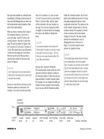
Tools You’ll Use
FIGURE 2
Four objects before and after being extruded
FIGURE 1
Identifying the Z-axis on an extruded object
LESSON 1
What You’ll Do
ILLUSTRATOR 11-4
Creating 3D Objects
Extruding Objects
Illustrator’s Extrude & Bevel effect applies a
three-dimensional effect to two-dimensional
objects. A two-dimensional object has two
axes: an X axis representing the width and a Y
axis representing the height. When you
extrude an object you add depth to an object
by extending it on its Z axis, as shown in
Figure 1. An object’s Z axis is always
perpendicular to the object’s front surface.
Figure 2 shows four 2D objects before and
after being extruded. Note the changes to
each object’s fill color on the front surface
and the light and dark shadings on the
other surfaces. These shadings create the
3D effect and are applied automatically
when the Extrude & Bevel effect is applied.
QUICKTIP
3D effects may produce fills with flaws. These are usually
screen aberrations—an issue with your monitor—and don’t
show when you print the document.
In this lesson, you will use the 3D Extrude
& Bevel effect to extrude objects.
▼
Two-dimensional
object
Three-dimensional
object
Before being
extruded
After being
extruded
EXTRUDE
OBJECTS
Lesson 1 Extrude Objects
ILLUSTRATOR 11-5
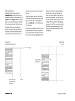
You determine the degree of extrusion by
changing the Extrude Depth value in the
3D Extrude & Bevel Options dialog box,
shown in Figure 3. Extrusion depth is
measured in points. The greater the value,
the more the object is extended on its Z axis,
as shown in Figure 4.
Use the Cap buttons in the 3D Extrude &
Bevel Options dialog box to make extruded
objects appear solid or hollow. The Turn cap
on for solid appearance button is the default
setting. It produces an object in which the
front and back faces (surfaces) are solid, as
shown in Figure 5. The Turn cap off for
FIGURE 4
Two objects extruded to different depths
FIGURE 3
3D Extrude & Bevel Options dialog box
FIGURE 5
Activating the “solid cap” button
Click to expose
Extrude Depth slider
Less extrusion More extrusion
Front and back faces
of object are solid
Turn cap on for solid
appearance button
FIGURE 7
Options for rotating 3D objects
ILLUSTRATOR 11-6
Creating 3D Objects
hollow appearance button makes the front
and back faces invisible, producing an object
that appears hollow, as shown in Figure 6.
Rotating 3D Objects
The 3D Extrude & Bevel Options dialog box
offers controls for rotating extruded objects.
You can rotate the object manually by drag-
ging the rotation cube, shown in Figure 7.
The three text boxes to the right of the cube
represent the selected object’s X, Y, and Z
axes. When you rotate the cube, the values
in these text boxes update to reflect the
changes you make. You may also enter
values in these text boxes to rotate the
selected object at specific angles.
Once an object has been extruded, you can
use the rotation cube to view any surface of
the object—front, back, left, right, etc. The
surface shading will update whenever you
rotate an object.
Object is rotated
Specify rotation around
the X axis text box
Specify rotation around
the Y axis text box
Specify rotation around
the Z axis text box
Rotation cube
FIGURE 6
Activating the “hollow cap” button
Front and back
faces of object
are hollow
Turn cap off for
hollow appearance
button
Lesson 1 Extrude Objects
ILLUSTRATOR 11-7
Extruding Compound Paths
Applying the Extrude & Bevel effect to a com-
pound path can yield results that are visually
very interesting. Figure 8 shows a simple
compound path—a circle with a square
“knocked out” from its center—positioned in
front of a light blue square. Figure 9 shows
the same object after being extruded.
Generally speaking, the more surfaces that
an object has, the more interesting the 3D
effect will be. Figure 10 shows a complex
compound path, and Figure 11 shows the
results when the Extrude & Bevel effect is
applied.
FIGURE 10
Complex compound path
FIGURE 11
Complex compound path, extruded
FIGURE 8
Simple compound path
FIGURE 9
Simple compound path, extruded
Compound path
Extrusion occurs on
all surfaces
ILLUSTRATOR 11-8
Creating 3D Objects
Applying a Bevel Edge to an
Extruded Object
The dictionary defines the term bevel as
the angle that one surface makes with
another when they are not at right angles.
Figure 12 shows an example of a graphic
with a bevel edge.
The Bevel menu, shown in Figure 13,
offers ten pre-defined bevel shapes that you
can apply to the edges of extruded objects.
The width of the bevel edge is controlled
by the Height slider. Figure 14 shows six
objects, each with a different bevel shape
applied to its edge. Each bevel has a width
of 4 points.
FIGURE 12
Identifying a bevel edge
FIGURE 13
Viewing the Bevel menu
FIGURE 14
Six objects with bevel shapes applied to edges
Choose from 1 of 10
bevel shapes
RoundedRollingJaggy
Classic
Complex 2
Cove
Lesson 1 Extrude Objects
ILLUSTRATOR 11-9
FIGURE 16
Extruded text with the Rounded bevel shape applied
FIGURE 15
Extruding text
The “X” is becoming
disfigured
As shown in Figure 15, text can be extruded
without first having to convert it to out-
lines. Once extruded, you can add a bevel
edge to text. Figure 16 shows the same text
with the Rounded bevel shape.
Because many letters are complex shapes,
applying a bevel to extruded text often causes
problems. Simply put, the shapes are too
intricate to be rendered with a bevel edge. In
Figure 16, the two Ts and the E handle the
bevel edge quite well, but you can see that
the X is becoming disfigured. In Figure 17,
the Classic bevel shape has been applied. The
X isn’t rendered properly with the Classic
bevel shape applied to its edge.
FIGURE 17
Identifying problems with a bevel edge
The “X” isn’t
rendered properly
ILLUSTRATOR 11-10
Creating 3D Objects
Whenever Illustrator is having difficulty
rendering an object with a bevel edge, a
warning appears in the 3D Extrude & Bevel
Options dialog box, shown in Figure 18.
When problems do occur, sometimes there
is no solution. Your best bet, however, is to
reduce the width of the bevel. Figure 19
shows the same text with the same Classic
bevel shape shown in Figure 17, but in
this figure, the bevel width has been
reduced from four points to three points.
The dialog box continues to warn that
there may be problems with the bevel edge.
Though that may be the case, the problems
are less obvious.
FIGURE 18
Warning regarding a bevel edge
FIGURE 19
Reducing the width of a bevel edge
Warning
The “X” is rendered
fairly well