GasTurbine Engineering HandbookSecond Edition phần 10 docx
Bạn đang xem bản rút gọn của tài liệu. Xem và tải ngay bản đầy đủ của tài liệu tại đây (617.21 KB, 78 trang )
G:/GTE/FINAL (26-10-01)/CHAPTER 21.3D ± 723 ± [722±777/56] 1.11.2001 4:00PM
Combining the practice of preventive maintenance and total quality con-
trol and total employee involvement results in an innovative system for
equipment maintenance that optimizes effectiveness, eliminates breakdowns,
and promotes autonomous operator maintenance through day-to-day activ-
ities. This concept known as Total Productive Maintenance (TPM) was
conceived by Seiichi Nakajima and is well-documented in his book ``Intro-
duction of TPM'' and is highly recommended reading for all involved in the
maintenance area.
A new maintenance system is introduced based on the new mantra for the
selection of all equipment ``Life Cycle Cost.'' This new system especially for
major power plants is based on the combination of total condition monitor-
ing, and the maintenance principles of total productive maintenance, and is
called the ``Performance Based Total Productive Maintenance System.''
The general maintenance system is fragmented and can be classified into
many maintenance concepts. The following are five P's of maintenance for
major power plants, petro-chemical corporations, and other process type
industries leading to the ultimate maintenance system:
1. Panic maintenance based on breakdowns
2. Preventive maintenance
3. Performance based maintenance
4. Performance productive maintenance
5. Performance based total productive maintenance (PTPM).
Performance based total productive maintenance consists of the following
elements:
1. Performance based total productive maintenance aims to maximize
equipment efficiency and time between overhaul. (overall perform-
ance effectiveness)
2. Performance based total productive maintenance aims to maximize
equipment effectiveness. (overall effectiveness)
3. Performance based total productive maintenance establishes a thor-
ough system of PM for the equipment's entire life span.
4. Performance based total productive maintenance is implemented by
various departments (engineering, operations, maintenance).
5. Performance based total productive maintenance involves every single
employee, from top management to workers on the floor.
6. Performance based total productive maintenance is based on the
promotions of PM through motivation management: autonomous
small group activities.
Maintenance Techniques 723
G:/GTE/FINAL (26-10-01)/CHAPTER 21.3D ± 724 ± [722±777/56] 1.11.2001 4:00PM
The word ``total'' in ``performance based total productive maintenance''
has four meanings that describe the principal features of PTPM:
1. Total overall performance effectiveness indicates PTPM's pursuit of
maximum plant efficiency and minimum downtime.
2. Total overall performance effectiveness indicates PTPM's pursuit of
economic efficiency or profitability.
3. Total maintenance system includes maintenance prevention (MP)
and maintainability improvement (MI) as well as preventive main-
tenance.
4. Total participation of all employees includes autonomous maintenance
by operators through small group activities.
Table 21-1 shows the relationship between PTPM, productive mainten-
ance, and preventive maintenance.
Performance based total productive maintenance eliminates the following
seven major losses:
Down time:
1. Loss of time due to unnecessary overhauls based only on time inter-
vals.
2. Equipment failure-from breakdowns.
3. Loss of time due to spare part unsuitability or insufficient spares.
Table 21-1
Benefits of Various Maintenance Systems Maintenance
Performance
Based Total
Productive
Maintenance
Performance
Productive
Maintenance
Performance
Based
Maintenance
Preventive
Maintenance
Panic
Maintenance
Economic
efficiency
Yes Yes Yes Yes No
Economic and
time efficiency
Yes Yes Yes No No
Total system
efficiency
Yes Yes No No No
Autonomous
maintenance
by operators
Yes No No No No
724 Gas Turbine Engineering Handbook
G:/GTE/FINAL (26-10-01)/CHAPTER 21.3D ± 725 ± [722±777/56] 1.11.2001 4:00PM
4. Idling and minor stoppagesÐdue to the abnormal operation of sen-
sors or other protective devices.
5. Reduced outputÐdue to discrepancies between designed and actual
operating conditions.
Defect:
1. Process defectsÐdue to improper process conditions that do not meet
machinery design requirements.
2. Reduced yieldÐfrom machine startup to stable production due to the
inability of the machine to operate at proper design conditions.
Maximization of Equipment Efficiency and Effectiveness
High machine efficiency and availability can be attained by maintaining
the health of the equipment. Total performance condition monitoring can
play a major part here as it provides early warnings of potential failures
and performance deterioration. Figure 21-1 shows the concept of a total
performance condition monitoring system.
Pure preventive maintenance alone cannot eliminate breakdowns. Break-
downs occur due to many factors such as, design and or manufacturing
errors, operational errors, and wearing out of various components. Thus,
changing out components at fixed intervals does not solve the problems and
in some cases adds to the problem. A study at a major nuclear power
station indicated that nearly 35% of the failures occurred within a month
of a major turnaround. Figure 21-2 shows the life characteristics of a major
piece of turbomachinery.
What-If Analysis
D-CS System
Gas and Steam
Turbine Control System
Aerothermal Data
D-CS System
Gas and Steam
Turbine Control System
Dynamic Vibration
Data
Mechanical Data
Analyze Data
Diagnose Data
Report Results
Figure 21-1. Total performance-based condition monitoring system.
Maintenance Techniques 725
G:/GTE/FINAL (26-10-01)/CHAPTER 21.3D ± 726 ± [722±777/56] 1.11.2001 4:00PM
The goal of any good maintenance program is ``Zero Breakdown.'' To
achieve this goal, there are five counter measures. These are listed below:
1. Maintaining well-regulated basic conditions (cleaning, lubricating,
and bolting).
2. Adhering to proper operating procedures.
3. Total condition monitoring (performance, mechanical, and diagnostic
based).
4. Improving weaknesses in design.
5. Improving operation and maintenance skills.
The interrelationship between these five items is shown in Figure 21-3.
The division of labor between operations and maintenance is shown in
Figure 21-4. It is the primary responsibility of the production department to
establish and regulate basic operating conditions, and it is the primary
responsibility of the maintenance department to improve defects in design.
The other tasks are shared between the two departments.
Preventive and
Maintainability
Improvement
Proper
Operation
Trial runs at
acceptance and
startup controls
Counter
Measures
Maintenance Prevention
Wear OutOperational Errors
Design
Manufacturing
Errors
Cause
Wear Out
Failure
Chance
Failure
Start up
Failure
Category
Useful Life
Chance Failure
Period
Failure Rate
Start Up
Failure
Period
Wear Out
Period
Operational Hours
Reduction of
Failure Through
Maintenance
Figure 21-2. Machinery life cycle characteristics.
726 Gas Turbine Engineering Handbook
G:/GTE/FINAL (26-10-01)/CHAPTER 21.3D ± 727 ± [722±777/56] 1.11.2001 4:00PM
The successful implementation of total productive maintenance requires:
1. Elimination of the six big losses to improve equipment effectiveness
2. An autonomous maintenance program with total condition monitoring
3. A scheduled maintenance program for the maintenance department
4. Increased skills of operations and maintenance personnel
5. An initial equipment management program
Maintain
Basic
Conditions
Adhere to
Operating
Procedures
Discover
and Predict
Deterioration
Establish
Repair
Methods
Restore
Deterioration
Correct
Defects
in Design
Prevent
Operation
Errors
Prevent
Repair
Errors
Prevent
Human
Errors
The Five Types of Breakdown Countermeasures
Improve Operation Skills
Improve Maintenance Skills
Figure 21-3. Breakdown countermeasures.
Establish
and regulate
basic
conditions
Adhere to
operating
procedures
Total
Condition
Monitoring
Improve
defects
in design
Improve
skills
Uncover Hidden Defects
Product Department
Maintenance Department
Figure 21-4. Responsibilities of the operations and maintenance departments.
Maintenance Techniques 727
G:/GTE/FINAL (26-10-01)/CHAPTER 21.3D ± 728 ± [722±777/56] 1.11.2001 4:00PM
Organization Structures for a Performance Based Total Productive
Maintenance Program
Typically successful implementation of PTPM in a large plant takes
three years. Implementation calls for:
1. Changing peoples attitudes
2. Increasing motivation
3. Increasing competency
4. Improving the work environment
The four major categories in developing a Performance Based Total
Productive Maintenance program are:
1. Preparation for the PTPM program
2. Preliminary implementation
3. PTPM implementation
4. Stabilization of the program
Implementation of a Performance Based Total Productive Maintenance
There are several steps involved in implementation of a PTPM pro-
gram.
1. Announcement of decision to implement PTPM. A formal presentation
must be made by top management introducing the concepts, goals,
and benefits of PTPM. Management commitment must be made clear
to all levels of the organization.
2. Educational campaign. The training and promotion of PTPM philo-
sophy is a must. This is useful to reduce the resistance to change. The
education should cover how PTPM will be beneficial to both the
corporation and the individuals.
3. Creation of organization to promote PTPM. The PTPM promotio-
nal structure is based on an organizational matrix. Obviously, the
optimal organizational structure would change from organization to
organization.
In large corporations, PTPM promotional headquarters must be
formed and staffed. Thus, any questions can be addressed here on a
corporate level.
4. Establishment of basic PTPM goals. Establishing mottos and slogans
can do this. All goals must be quantifiable and precise specifying:
728 Gas Turbine Engineering Handbook
G:/GTE/FINAL (26-10-01)/CHAPTER 21.3D ± 729 ± [722±777/56] 1.11.2001 4:00PM
a. Target (what)
b. Quantity (how much)
c. Time Frame (when)
5. Master plan development for PTPM. A master plan must be created.
Total condition monitoring equipment should be designed, and
equipment should be purchased.
6. Initiation of PTPM. This represents a ``kickoff '' stage. At this point,
the whole staff must start to get involved.
7. Improvement of equipment effectiveness. This should start with a
detailed design review of the plant machinery. A performance analysis
of the plant could point to a specific area known to have problems
(i.e., section of plant) must be selected and focused on, project teams
should be formed and assigned to each train. An analysis should be
conducted that address the following:
a. Define the problem. Examine the problem (loss) carefully; com-
pare its symptoms, conditions, affected parts, and equipment with
those of similar cases.
b. Do a physical analysis of the problem. A physical analysis clarifies
ambiguous details and consequences. All losses can be explained
by simple physical laws. For example, if scratches are frequently
produced in a process, friction or contact between two objects
should be suspected. (Of the two objects, scratches will appear in
the object with the weaker resistance.) Thus, by examining the
points of contact, specific problem areas and contributing factors
are revealed.
c. Isolate every condition that might cause the problem. A physical
analysis of breakdown phenomena reveals the principles that
control their occurrence and uncovers the conditions that produce
them. Explore all possible causes.
d. Evaluate equipment, material, and methods. Consider each condi-
tion identified in relation to the equipment, jigs and tools, mater-
ial, and operating methods involved, and draw up a list of factors
that influence the conditions.
e. Plan the investigation. Carefully plan the scope and direction of
investigation for each factor. Decide what to measure and how to
measure it and select the datum plane.
f. Investigate malfunctions. All items planned in step 5 must be
thoroughly investigated. Keep in mind optimal conditions to be
achieved and the influence of slight defects. Avoid the traditional
factor analysis approach; do not ignore malfunctions that might
otherwise be considered harmless.
Maintenance Techniques 729
G:/GTE/FINAL (26-10-01)/CHAPTER 21.3D ± 730 ± [722±777/56] 1.11.2001 4:00PM
g. Formulate improvement plans. Define consultants who could do
re-design the given piece of equipment. Discuss with manufac-
turers your plans.
8. Establishment of autonomous maintenance program for operators.
This is focused against the classic ``Operations'' versus ``Mainte-
nance'' battle. Operators here must be convinced that they should
maintain their own equipment. For example, an attitude has to be
developed for operators to understand and act on the reports pro-
duced by the on-line performance condition monitoring systems.
9. Setup of scheduled maintenance program. Scheduled maintenance
conducted by the maintenance department must be smoothly coor-
dinated with autonomous maintenance done by the plant operators.
This can be done by frequent meetings and plant audits. In most
plants an undeclared conflict exists between the operations and
maintenance groups. This arises from the false perception that these
two groups having conflicting goals. The PTPM philosophy will go a
long way in bringing these groups together.
10. Training for improvement of operation and maintenance skills. This is
a key part of PTPM. Ongoing training in advanced maintenance
techniques, tools, and methods must be done. This could cover areas
such as:
a. Bearings and seals
b. Alignment
c. Balancing
d. Vibration
e. Troubleshooting
f. Failure analysis
g. Welding procedures
h. Inspection procedures
i. NDT
11. Equipment management program. Startup problems, solutions, and
design changes should be clearly documented and available for a
good equipment management plan. All items that can reduce Life
Cycle Costs (LCC) should be considered. These include:
a. Economic evaluation at the equipment-investment stage
b. Consideration of MP or maintenance-free design and economic
LCC
c. Effective use of accumulated MP data
d. Commissioning control activities
e. Thorough efforts to maximize reliability and maintainability
730 Gas Turbine Engineering Handbook
G:/GTE/FINAL (26-10-01)/CHAPTER 21.3D ± 731 ± [722±777/56] 1.11.2001 4:00PM
12. Final implementation of PTPM. This stage involves the refinement of
PTPM and the formulation of new goals that meet specific corporate
needs.
Maintenance Department Requirements
To ensure the success of the PTPM program, the maintenance department
must be well equipped and trained. The following six basic categories are
prerequisite to the proper functioning of the Maintenance Department
under the PTPM:
1. Training of personnel
2. Tools and equipment
3. Condition and life assessment
4. Spare parts inventory
5. Redesign for higher machinery reliability
6. Maintenance scheduling
7. Maintenance communication
8. Inspections
Training of Personnel
Training must be the central theme. The days of the mechanic armed with
a ball-peen hammer, screwdriver, and a crescent wrench are gone. More and
more complicated maintenance tools must be placed in the hands of the
mechanic, and he must be trained to utilize them.
People must be trained, motivated and directed so that they gain
experience and develop, not into mechanics, but into highly capable techni-
cians. While good training is expensive, it yields great returns. Machinery
has grown more complex, requiring more knowledge in many areas. The old,
traditional craft lines must yield before complicated equipment maintenance
needs. A joint effort by craftsmen is necessary to accomplish this.
I. Type of Personnel
a. Maintenance Engineer.
In most plants, the maintenance engineer is
a mechanical engineer with training in the turbomachinery area. His needs
are to convert what he has learned in the classroom into actual hands-on
solutions. He must be well versed in a number of areas such as performance
analysis, rotor dynamics, metallurgy, lubrication systems, and general
shop practices. His training must be well planned so that he can pick up
Maintenance Techniques 731
G:/GTE/FINAL (26-10-01)/CHAPTER 21.3D ± 732 ± [722±777/56] 1.11.2001 4:00PM
these various areas in steps. His training must be a combination of a hands-
on approach coupled with the proper theoretical background. He should be
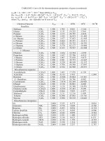
well versed in the various ASME power test codes. Table 21-2 is a listing of
some of the applicable codes for gas turbine power plants. Attendance at
various symposiums where users of machinery get together to discuss
problems should be encouraged. It is not uncommon to find a solution to
a problem at these types of round table discussions.
b. Foremen and Lead Machinist. These men are the key to a good
maintenance program. They should be sent frequently to training schools
to enhance their knowledge. Some plants have one foreman who is an
``in-house serviceman;'' he supervises no personnel, but acts as an in-house
consultant on maintenance jobs.
c. Machinist/Millwright. The machinist should be encouraged to oper-
ate most of the machinery in the plant maintenance shop. By rotating him
among various jobs, his learning and development is accelerated. He should
then become as familiar with a large compressor as a small pump. Encour-
agement should be given to the machinist to learn balancing operations and
to participate in the solution of problems.
Spreading around the hardest jobs develops more competent people and is
the basis of any PTPM program. Restricting a man to one type of work will
probably make him an expert in that area, but his curiosity and initiative,
prime motivators, will eventually fade.
II. Types of Training
a. Update Training.
This training is mandatory for all maintenance
personnel, so that they may keep abreast of this high technology industry.
Table 21-2
Performance Test Codes
1. ASME, Performance Test Code on Overall Plant Performance, ASME PTC 46 1996,
American Society of Mechanical Engineers, 1996
2. ASME, Performance Test Code on Test Uncertainty: Instruments and Apparatus
PTC 19.1, 1988
3. ASME, Performance Test Code on Gas Turbines, ASME PTC 22 1997, American
Society of Mechanical Engineers, 1997
4. ASME, Performance Test Code on Gas Turbine Heat Recovery Steam Generators,
ASME PTC 4.4 1981, American Society of Mechanical Engineers, Reaffirmed 1992
5. ASME Gas Turbine Fuels B 133.7M Published: 1985 (Reaffirmed year: 1992)
6. ISO, Natural GasÐCalculation of Calorific Value, Density and Relative Density
International Organization for Standardization ISO 6976-1983(E)
732 Gas Turbine Engineering Handbook
G:/GTE/FINAL (26-10-01)/CHAPTER 21.3D ± 733 ± [722±777/56] 1.11.2001 4:00PM
Personnel must be sent to manufacturer-conducted schools. These schools,
in turn, should be encouraged to cover some basic machinery principles
as well as their own machinery. In-house seminars should be provided
with in-house personnel and consultants at the plant. Engineers should
be sent to various schools so that they may be exposed to the latest
technology.
An in-house website, cataloging experiences and special maintenance
techniques should be updated and available for the entire corporation
especially maintenance and operation personnel. These websites should be
full of illustrations, short, and to the point.
A small library should be adjacent to the shop floor, with field drawings,
written histories of equipment, catalogs, API specifications, and other lit-
erature pertinent to the machine maintenance field. Drawings and manuals
should be transferred to the electronic digital media as soon as possible.
Access to the Internet on the maintenance and production area computers is
a must as many manufacturers post helpful operational and maintenance
hints on their websites. API specifications, which govern mechanical
machinery, are listed in Table 21-3.
Manufacturer instruction books are often inadequate and need to be
supplemented. The re-writing of maintenance manuals on such subjects as
mechanical seals, vertical pumps, hot-tapping machines, and gas and steam
turbines are not uncommon. The turbine overhaul manuals transferred
on CD's could consist of (1) step-by-step overhaul procedures, developed
largely from the manufactures training school, (2) hundreds of photographs,
illustrating the step-by-step procedures on various types of gas and steam
turbines, (3) an arrow diagram showing the sequences of the procedures,
and, (4) typical case histories.
Detailed drawings on CD's are developed to aid in maintenance, such as a
contact seal assembly, because the ``typical'' dimensionless drawing supplied
by the OEM is not adequate to correctly assemble the compressor seals.
Many other assembly drawings should be developed to facilitate the overall
maintenance program. Videotaped programs are being developed on seals,
bearings, and rotor dynamics, which will be a tremendous asset to most
company maintenance programs.
b. Practical Training. The engineers in the maintenance group should
be encouraged to gather pertinent vibration and aerothermal data and ana-
lyze the machinery. ASME performance specifications, which govern all
types of power plants and other critical equipment, are listed in Table 21-2.
They should be encouraged to work closely at the various maintenance
schedules and turnarounds so that they are familiar with the machinery.
Maintenance Techniques 733
G:/GTE/FINAL (26-10-01)/CHAPTER 21.3D ± 734 ± [722±777/56] 1.11.2001 4:00PM
They should be sent to special training sessions where hands-on experience
can be gained.
After the completion of basic machinist training, the machinist should
continue his training with on-the-job experiences. His skills should be tested,
and he should be encouraged to take on different tasks.
To develop the skills of in-house personnel, as much repair work as pos-
sible should utilize plant personnel. Encouraging the participation of the
machinist in the solution of difficult problems often results in the machinist
seeking information on his own. References to API and ASME specifications
should not be uncommon on the shop floor. Today's machinist and mechanic
must be computer literate. Internet training must be provided with some basic
training on word processing and spreadsheet programs.
Table 21-3
Mechanical Specifications
ASME Basic Gas Turbines B 133.2 Published: 1977 (Reaffirmed year: 1997)
ASME Gas Turbine Control and Protection Systems B133.4 Published: 1978 (Reaffirmed
year: 1997)
ASME Gas Turbine Installation Sound Emissions B133.8 Published: 1977 (Reaffirmed:
1989)
ASME Measurement of Exhaust Emissions from Stationary Gas Turbine Engines B133.9
Published: 1994
ASME Procurement Standard for Gas Turbine Electrical Equipment B133.5 Published:
1978 (Reaffirmed year: 1997)
ASME Procurement Standard for Gas Turbine Auxiliary Equipment B133.3 Published:
1981 (Reaffirmed year: 1994)
ANSI/API Std 610 Centrifugal Pumps for Petroleum, Heavy Duty Chemical and Gas
Industry Services, 8th Edition, August 1995 (-1995)
API Std 613 Special Purpose Gear Units for Petroleum, Chemical and Gas Industry
Services, 4th Edition, June 1995
API Std 614, Lubrication, Shaft-Sealing, and Control-Oil Systems and Auxiliaries for
Petroleum, Chemical and Gas Industry Services, 4th Edition, April 1999
API Std 616, Gas Turbines for the Petroleum, Chemical and Gas Industry Services, 4th
Edition, August 1998
API Std 617, Centrifugal Compressors for Petroleum, Chemical and Gas Industry
Services, 6th Edition, February 1995
API Std 618, Reciprocating Compressors for Petroleum, Chemical and Gas Industry
Services, 4th Edition, June 1995
API Std 619, Rotary-Type Positive Displacement Compressors for Petroleum, Chemical,
and Gas Industry Services, 3rd Edition, June 1997
ANSI/API Std 670 Vibration, Axial-Position, and Bearing-Temperature Monitoring
Systems, 3rd Edition, November 1993
API Std 671, Special Purpose Couplings for Petroleum Chemical and Gas Industry
Services, 3rd Edition, October 1998
734 Gas Turbine Engineering Handbook
G:/GTE/FINAL (26-10-01)/CHAPTER 21.3D ± 735 ± [722±777/56] 1.11.2001 4:00PM
c. Basic Machinist Training. Most of the basic training can be devel-
oped and conducted by in-plant personnel. This training can be highly
detailed and tailored precisely to meet individual plant requirements. Train-
ing must be carefully planned and administered to fit the requirements of
different machinery in the plant.
Many plants have a full-time training program, and personnel for con-
ducting training at this basic level. Good maintenance practices should be
inculcated into the young machinist from the beginning. He should be taught
that all clearances should be carefully checked, and noted both before and
after reassembly. He should learn the proper care in the handling of instru-
mentation, and the care in placing and removing seals and bearings. A base
course on the major turbomachinery principles is a must, so there is basic
understanding of what these machines do and how they function. The young
machinist should also be exposed to basic machinery-related courses such as:
1. Reverse indicator alignment
2. Gas and steam turbine overhaul
3. Compressor overhaul
4. Mechanical seal maintenance
5. Bearing maintenance
6. Lubrication system maintenance
7. Single plane balancing
Tools and Shop Equipment
A mechanic must be supplied with the proper tools to facilitate his jobs.
Many special tools are required for different machines, so as to ensure
proper disassembly and reassembly. Torque wrenches should be an integral
part of his tools, as well as of his vocabulary.
The concepts of ``finger tight'' and ``hand tight'' can no longer be applied
to high-speed, high-pressure machinery. A recent major explosion at an
oxygen plant, which resulted in a death, was traced back to gas leakage
due to improper torquing. A good dial indicator and special jigs for taking
reverse indicator dial readings is a must. The jigs must be specially made for
the various compressor and turbine trains. Special gear and wheel pullers are
usually necessary.
Equipment for heating wheels in the field for assembly and disassembly
are needed; specially designed gas rings are often used for this purpose.
A maintenance shop should have the traditional horizontal and vertical
lathes, mills, drill presses, slotters, bores, grinders, and a good balancing
machine. A balancing machine can pay for itself in a very short time in
Maintenance Techniques 735
G:/GTE/FINAL (26-10-01)/CHAPTER 21.3D ± 736 ± [722±777/56] 1.11.2001 4:00PM
providing a fast turnaround and accurate dynamic balance. Techniques to
check the balance of gear-type couplings for the large high-speed compres-
sors and turbine drives, as a unit should be developed. This leads to the
solving of many vibration related problems. High-speed couplings should
be routinely check-balanced.
By dynamically balancing most parts, seal life and bearing life is greatly
improved, even on smaller equipment. Dynamic balancing is needed on pump
impellers, as the practice of static balance is woefully inadequate. Vertical
pumps must be dynamically balanced; the long, slender shafts are highly
susceptible to any unbalanced-induced vibration.
This assembly and disassembly of rotors must be in a clean area. Horses or
equivalents should be available to hold the rotor. The rotor should rest on
the bearing journals, which must be protected by soft packing, or the
equivalent, to avoid any marring of the journals. To accomplish uniform
shrink fits, the area should have provisions for heating and/or cooling.
A special rotor-testing fixture should be provided; this is very useful in
checking for wheel wobbles, wheel roundness, and shaft trueness. Rotors
in long-term storage should be stored in a vertical position in temperature-
controlled warehouses.
Spare Parts Inventory
The problem of spare parts is an inherent phase of the maintenance
business. The high costs of replacement parts, delivery, and in some
instances, poor quality, are problems faced daily by everyone in the main-
tenance field. The cost of spare parts for a major power plant or refinery
runs into many millions of dollars.
The inventory of these plants can run into over 20,000 items, including
over 100 complete rotor systems. The field of spare parts is changing rapidly
and is much more complex than in the past. A group of plants have gotten
together in a given region and formed ``Part Banks.''
Many pieces of equipment are made up of unitized components from
several different vendors. The traditional attitude has been to look to the
packaging vendor as the source of supply. Many vendors refuse to handle
requests for replacement parts on equipment not directly manufactured by
them. More and more specialty companies are entering the equipment parts
business; some are supplying parts directly to OEM companies for resale as
their ``own'' brand. Others supply parts directly to the end user. The end
user must develop multiple sources of supply for as many parts as possible.
Gaskets, turbine carbon packing, and mechanical seal parts can be pur-
chased from local sources. Shafts, sleeves, cast parts can be purchased from
736 Gas Turbine Engineering Handbook
G:/GTE/FINAL (26-10-01)/CHAPTER 21.3D ± 737 ± [722±777/56] 1.11.2001 4:00PM
local sources. Shafts, sleeves, cast parts such as impellers, are becoming
increasingly available from specialty vendors. All this competition is causing
the OEM's to alter their spare parts system to improve service and reduce
prices, which is definitely a bright spot in the picture. The quality control of
both OEM and some specialty houses leaves much to be desired. In turn, this
causes many plants to have an in-house quality control person checking all
incoming parts, a concept highly recommended.
Condition and Life Assessment
Condition and life assessment is significant for all types of plants, and
especially Combined Cycle Power Plants. The most important aspect of a
plant is high availability, and reliability, in some cases even more significant
than higher efficiency.
The availability of a power plant is the percent of time the plant is
available to generate power in any given period. The reliability of the plant
is the percentage of time between planed overhauls.
The availability of a power plant is defined as
A
P À S À F
P
21-1
where:
P Period of time, hours, usually this is assumed as one year, which
amounts to 8,760 hours
S Scheduled outage hours for planned maintenance
F Forced outage hours or unplanned outage due to repair
The reliability of a power plant is defined as
R
P À F
P
21-2
Availability and reliability have a very major impact on the plant econ-
omy. Reliability is essential in that when the power is needed it must be there.
When the power is not available it must be generated or purchased, and can
be very costly in the operation of a plant. Planned outages are scheduled for
non-peak periods. Peak periods is when the majority of the income is gener-
ated as usually there are various tiers of pricing depending on the demand.
Many power purchase agreements have clauses, which contain capacity
payments, thus making plant availability critical in the economics of the plant.
Gas turbines with the new technology, higher pressure ratio and higher
firing temperature, has led to the building of large gas turbines producing
Maintenance Techniques 737
G:/GTE/FINAL (26-10-01)/CHAPTER 21.3D ± 738 ± [722±777/56] 1.11.2001 4:00PM
nearly 300 MW and reaching gas turbine efficiencies in the mid forties. The
availability factor for units with mature technology, below 100 MW, are
between 94
Â
±97%, while the bigger units above 100 MW have availability
factors of 85
Â
±89%. The bigger units produce twice the output, but the avail-
ability factor has decreased from 95% to 85%. A decrease of 7
Â
±10 points
for all manufacturers. Part of this decrease may be related to larger machinery
taking more time to repair. It is also due to the high temperature and pressure.
The increase in unit size and complexity together with the higher turbine
inlet temperature, and higher pressure ratio has lead to an increase in overall
gas turbine efficiency. The increase in efficiency of 7
Â
±10% has in many cases
lead to an availability decrease of the same amount or even more as seen in
Figure 21-5. A 1% reduction in plant availability could cost $500,000/yr in
income on a 100 MW plant, thus in many cases offsetting gains in efficiency.
Reliability of a plant depends on many parameters, such as the type of
fuel, the preventive maintenance programs, the operating mode, the control
systems, and the firing temperatures.
Redesign for Higher Machinery Reliability
Low reliability of units gives rise to high maintenance costs. Low reli-
ability is usually a greater economic factor than the high maintenance costs.
96
35
85
45
0
10
20
30
40
50
60
70
80
90
100
Below 100 MW Above 100 MW
Availability
Efficiency
Figure 21-5. Comparison of availability and efficiency for large frame type gas
turbines.
738 Gas Turbine Engineering Handbook
G:/GTE/FINAL (26-10-01)/CHAPTER 21.3D ± 739 ± [722±777/56] 1.11.2001 4:00PM
In many large power plants, refineries, and petrochemical complexes,
about one-third of the failures are due to machinery failure; it is therefore
necessary to redesign parts of a machine to improve reliability.
The maintenance practice of one large refinery is to replace gas turbine
control systems with state-of-the-art electronics and ``plug-in'' concepts for
ease of maintenance. These installations have been highly successful in that
maintenance has been minimal, and can usually be accomplished on-stream.
Another replaces all journal bearings with tilting pad bearings.
In addition, the new control systems increase turbine performance,
while speed control and flexibility are greatly improved. The original design
has been supplemented to include a self-contained alarm system, a semi-
automatic sequential start system, and a complete trip and protection
system, as well as the electronic controls. The cost of this system is substan-
tially less than the cost of a similar device offered by the OEM on new
machines.
The gas turbines major limitations on the life are the combustor cans,
first stage turbine nozzles and first stage turbine blades as seen in Figure 21-6.
The effect of dry Low NO
x
combustors have been very negative on the
availability of Combined Cycle Power Plants, especially those with dual
fuel capability. Flash back problems are a very major problem as they tend
to create burning in the pre-mix section of the combustor, and cause failure
of the pre-mix tubes. These pre-mix tubes are also very susceptible to
resonance vibrations.
Bearing failures are one of the major causes of failures in turbomachinery.
The changing of various types of radial bearings from cylindrical and/or
5
27
21
17
15
7
2
2
0
5
10
15
20
25
30
Compressor
Blades
Combustor
Cans
First Stage
Nozzles
First Stage
Blades
Controls Bearings Seals Couplings Generator
4
Figure 21-6. Contributions of various major components to gas turbine down time.
Maintenance Techniques 739
G:/GTE/FINAL (26-10-01)/CHAPTER 21.3D ± 740 ± [722±777/56] 1.11.2001 4:00PM
pressure dam babbitted sleeve bearings to tilting pad journal bearings is
becoming common in the industry. In most cases, this gives better stability,
eliminates oil whirl, and under misalignment condition, is more forgiving.
Thrust bearing changes, from the simple, tapered land thrust bearings to
tilting pad thrust bearings with leveling links (Kingsbury type), is another
area of common change. These types of bearings absorb sudden load surges
and liquid slugs. Many users have changed out the inactive thrust bearing to
carry the same load as the active thrust bearings. This has been the case in
older gas turbines where traditionally the load carrying capacity of the
inactive thrust bearing was 1/3 of the active thrust bearing. As gas turbines
got older the leakages increased and the thrust forces were altered greatly
leading to failures in the inactive thrust bearings.
A major plant replaces the entire large journal and thrust bearings in their
main machinery to tilting pad bearings in their plant as a matter of practice.
Material changes of the babbit are sometimes undertaken. Changing from
the more common steel backed babbitted bearings to the copper alloys, with
this babbitted pads, conducts surface heat away at a faster rate, thus increas-
ing the load carrying capacity. In some instances, a 50
Â
±100% load carrying
capacity improvement can be achieved. Some equipment manufacturers are
offering bearing-upgrading kits for their machine in service.
Design of turbine blades to obtain higher efficiency and damping has been
done. In some cases, this has improved efficiency by 8
Â
±10%, and stopped
failures in these blades. Steam injection has been utilized in gas turbines to
improve efficiency and to increase the power output. Redesign of various
bleed-off ports has reduced tip stalls and their accompanying blade failures.
Today's machinery, which is pushing the state-of-the-art in design, needs
more than ``simple fixes.'' This is one major reason why so much redesign
takes place in the field. Maintenance engineers are no longer just required to
repair, they are required in many cases to make revisions. Continual
improvements and updating of the machinery is required to obtain the long
runs and high efficiencies desirable in today's turbomachinery.
Maintenance Scheduling
The scheduling of maintenance inspections and overhauls is an essential
part of the total maintenance philosophy. As we move from ``Breakdown''
or ``Panic'' maintenance towards a performance based total productive
maintenance system, total condition monitoring and diagnostics becomes
an integral part of both operation and maintenance. Total condition
monitoring and diagnostic examines both the mechanical and performance
740 Gas Turbine Engineering Handbook
G:/GTE/FINAL (26-10-01)/CHAPTER 21.3D ± 741 ± [722±777/56] 1.11.2001 4:00PM
of the machinery and then carries out diagnostics. Condition monitoring
systems, which are only mechanical systems without performance inputs
give less than half of the picture and can be very unreliable. Unscheduled
maintenance is very costly and should be avoided. To properly schedule
overhauls, both mechanical and performance data must be gathered
and evaluated. As indicated earlier, we want to consider repairs during
a planned ``turnaround'' not ``random'' repairs, which are frequently done
on an ``emergency'' basis and where, due to time restraints, techniques
are sometimes used, which are questionable and should only be used in
emergencies.
To plan for a ``turnaround,'' one must be guided by the operating
history of the given plant and, if it is the first ``turnaround,'' by conditions
found in other plants utilizing the same or closely similar process and
machinery. This is how the time between subsequent ``turnarounds'' has
been extended to three years or more in many instances. By utilizing the
operating history and inspection at previous ``turnarounds'' at this or
similar installations, one can get a fair idea of what parts are most likely
to be found deteriorated and, therefore, must be replaced and/or repaired,
and what other work should be done to the unit while it is down. It should
be pointed out that, with modern turbomachinery, items such as bearings,
seals, filters and certain instrumentation, which are precision made, are
seldom, if ever, repaired except in an emergency; such items are replaced
with new parts.
This means that parts must be ordered in advance for the ``turnaround''
and other work must be planned so that the whole operation may proceed
smoothly and without holdups that could have been foreseen. This usually
means close collaboration with the manufacturer or consultant and the
OEM (or specialty service shop) so that handling facilities, service men,
parts, cleaning facilities, inspection facilities, chrome plating and/or metaliz-
ing facilities, balancing facilities, and some cases even heat treatment facil-
ities, are available and will be open for production at the proper time
required. This is the planning, which must be done in detail before the
shutdown with sufficient lead-time available in order to have replacement
parts available at the job site.
The old maxim ``if it ain't broke don't fix it'' is very applicable in
today's machinery. A study conducted at a major nuclear power facility
found that 35% of the failures occurred after a major turnaround. This is
why total condition monitoring is necessary in any performance based
total productive maintenance system and leads to overhauls being
planned on proper data evaluation of the machinery rather than on a
fixed interval.
Maintenance Techniques 741
G:/GTE/FINAL (26-10-01)/CHAPTER 21.3D ± 742 ± [722±777/56] 1.11.2001 4:00PM
Maintenance Communications
It is not uncommon to hear the complaint that the maintenance depart-
ment has ``never been informed as to what is happening in the plant.'' If this
is a common complaint, the maintenance manager needs to examine the
communications in his department. The following are six practical sugges-
tions for improving communications:
1. Operation and service manuals
2. Continuous updating of drawing and print files
3. Updating of training materials
4. Pocket guides
5. Written memos, interoffice E-mails
6. Seminars
7. Website postings
Each of these items listed, if properly employed, can transmit knowledge
to the person who must keep the plant's machinery running. How well the
information is transmitted depends entirely on the communication skills
applied to the preparation of the materials.
Operation and Service Manuals. To be of real value to the mechanic,
an operation and service manual must be indexed to permit quick location of
needed information. The manual must be written in simple, straightforward
language, have illustrations, sketches, or exploded views adjacent to pertin-
ent text, and have minimum references to another page or section. Major
sections or chapters should be tabbed for quick location.
Most often a mechanic or serviceman refers to a manual because of a
problem. Problems seem to happen during a production run. It is essential,
therefore, that he be able to find the needed information quickly. The
mechanic should not be delayed by wordy, irrelevant text. The objective
of any manual is to be an effective, immediate source of service informa-
tion.
The assignment of a nontechnical person to write a manual is shortsighted
and more costly in the long run. A well-written manual is continuously in
use. Good manuals need not be complicated. In fact, the simpler the better.
Manuals should be readable and understandable, whether they are compiled
in-house or outside.
Drawing and Print File. A good print file is a vital tool for any main-
tenance organization. Reference files in a large or multi-plant company can
be particularly burdensome for several reasons:
742 Gas Turbine Engineering Handbook
G:/GTE/FINAL (26-10-01)/CHAPTER 21.3D ± 743 ± [722±777/56] 1.11.2001 4:00PM
1. Prints are bulky and difficult to store properly
2. Control of use is necessary
3. Files must be kept up to date
4. Handling and distribution of new or revised prints is usually expensive.
A practical solution is to digitize the drawings and place them on CD's
available to the maintenance and operation department. A good digital file
reduces search time and helps the departments do a better job of keeping the
machinery operating at their peak efficiency with minimal downtime.
Training Materials. Like any other written or audio-visual maintenance
tool, training materials of all kinds are basically communication devices, and
to be effective, should be presented in a simple straightforward, attractive,
and professional manner.
Once the need for specific maintenance training has been determined, a
program must be developed. If the training need applies to a proprietary
machine or one that is unique to a very few industries, it might be necessary
to contact companies who specialize in custom digital programs on CD's,
slide/tape, movie, videotape, or written training programs. The cost may
shock the uninitiated, but after shopping around, the company may find that
it can recover far more than the initial cost in tangible benefits over a
relatively short period.
Pocket Guide. When a new maintenance form or procedure is introduced,
a quick reference pocket guide can promote understanding and accuracy. The
key to effectiveness is a deliberate design to provide maximum illustrations or
examples in simple language. If it cannot be prepared in-house, outside help
should be sought. Professionalism is essential to good communications.
Written Memos. One of the most effective devices for improving main-
tenance communications is a newsletter or internal memo. The memo's
success depends heavily on communicating formal tips and techniques in
the mechanics language and using photos, sketches, and drawings gener-
ously to get the message across.
Everyone in the maintenance department should be encouraged to con-
tribute ideas on a better way to do a task or a solution to a nagging prob-
lem related to the maintenance or operation of production equipment. Each
contributor should be given credit by name and location for his or her effort.
Very few workers can resist a bit of pride in seeing their names attached to an
article that is seen by virtually everyone in the company.
Seminars and Workshops. College or industry-sponsored seminars,
continuing education courses, and workshops are means of upgrading or
Maintenance Techniques 743
G:/GTE/FINAL (26-10-01)/CHAPTER 21.3D ± 744 ± [722±777/56] 1.11.2001 4:00PM
sharpening skills of maintenance people. Such an approach serves a twofold
purpose. First, it communicates the company's good faith in the person's
ability to benefit from the experience, and by acceptance, the worker shows
willingness to improve his or her usefulness to the company. The seminars
are very useful in disseminating knowledge. They also provide forum for
gripes and meaningful solutions. Discussion groups in these seminars and
workshops are very important as participants share experiences and solu-
tions to problems. The knowledge gained from these seminars is very useful.
Inspection
As with any power equipment, gas turbines require a program of planned
inspections with repair or replacement of damaged components. A properly
designed and conducted inspection and preventive maintenance program
can do much to increase the availability of gas turbines and reduce unsched-
uled maintenance. Inspections and preventive maintenance can be expensive,
but not as costly as forced shutdowns. Nearly all manufacturers emphasize
and describe preventive maintenance procedures to ensure the reliability of
their machinery, and any maintenance program should be based on manu-
facturer's recommendations. Inspection and preventive maintenance proce-
dures can be tailored to individual equipment application with references
such as the manufacturer's instruction book, the operator's manual, and the
preventive maintenance checklist.
Inspections range from daily checks made while the unit is operating to
major inspections that require almost total disassembly of the gas turbine.
Daily inspections should include (but are not limited to) the following
checks:
1. Lubrication oil level
2. Oil leakage around the engine
3. Loose fasteners, pipe and tube fittings, and electrical connections
4. Inlet filters
5. Exhaust system
6. Control and monitoring system indicator lights
The daily inspection should require less than an hour to perform properly
and can be made by the operator.
The interval between more thorough inspections will depend on the
operating conditions of the gas turbine. Manufacturers generally provide
guidelines for determining inspection intervals based on exhaust gas
temperatures, type and quality of fuel utilized, and number of starts.
744 Gas Turbine Engineering Handbook
G:/GTE/FINAL (26-10-01)/CHAPTER 21.3D ± 745 ± [722±777/56] 1.11.2001 4:00PM
Table 12-2 shows time intervals for various inspections based on fuels and
startups. Minor inspections should be performed after about 3000
Â
±6000
hours of operation, or after approximately 200 starts, whichever comes
first. This inspection requires a shutdown for two to five days, depending
on availability of parts and extent of repair work to be done. During this
inspection, the combustion system and turbine should be checked.
The first minor inspection or overhaul of a turbine forms the most
important datum point in its maintenance history, and it should always be
made under the supervision of an experienced engineer. All data should be
carefully taken and compared with the turbine erection information to
ascertain if any setting changes, misalignment, or excessive wear have
occurred during operation. Subsequent inspections are also of great impor-
tance, since they verify manufacturers' recommendations or help to establish
maintenance trends for particular operating conditions.
When the established time for major maintenance approaches, a meet-
ing should be arranged between the operating department and the
manufacturer's engineer to discuss and arrange for the date of turbine
outage. A short time before taking the turbine out of service a complete
operational test should be made at zero, one-half, and normal maximum
loads, preferably in the presence of the manufacturer's engineer. These
tests are for reference temperatures and pressures, which will serve as
a means of comparison with identical tests that should be made immedi-
ately after the unit is overhauled. The operational tests should end with
an over-speed trip test to indicate whether attention should be given to
the governor or tripping mechanism during the shutdown. These specific
data will also serve together with the logged operational data or case
history (which should be reviewed with the manufacturer's engineer) to
determine the focal point or items requiring special attention or investiga-
tion:
1. Increase or change in vibration
2. Decrease in air compressor discharge pressure
3. Change in lube oil temperatures or pressure
4. Air or combustion gases blowing out at the shaft seals
5. Incorrectly reading thermocouples
6. Change in wheel space temperatures
7. Fuel oil or gas leakage
8. Fuel control valves operate satisfactorily
9. Hydraulic control oil pressures changed
10. The turbine governor ``hunts''
11. Change in sound level of gear boxes
Maintenance Techniques 745
G:/GTE/FINAL (26-10-01)/CHAPTER 21.3D ± 746 ± [722±777/56] 1.11.2001 4:00PM
12. Overspeed devices operate satisfactorily
13. Babbitt or other material found on lubricating oil screens
14. Lube oil analysis shows corrosion factor increase
15. Change in pressure drop across heat exchangers
16. Turbogenerator reaches rated load at design ambient and exhaust
temperature conditions
Preparation for shutdown should be made as complete as possible to
eliminate lost time and confusion at the beginning of the job.
A list should be made of all major items that are to be inspected or repairs
to be made if they are known at the time. This list should be prepared with
the manufacturer's engineer present. A detailed schedule should be formu-
lated from this list including the time allotted for the shutdown and the
maintenance crew available. Plan the work with the expectation of finding
the worst conditionsÐthe unexpected work found after the machine is
opened will then be compensated. This procedure will greatly reduce the
possible need for costly overtime.
Tools on-site should be reviewed by the manufacturer's engineer. All
special or regular equipment not on hand that is necessary or required to
do any part of the work should be ordered and on-site before shutdown.
Exact outage time should be arranged, and the turbine prepared for the
contracting crew or plant maintenance crew. All personnel should be on the
job or available to meet the starting date.
Facilities, such as convenient air and electrical connections, should be
prearranged for operating tools, etc. Sufficient hose lengths and connectors
are required as well as electrical extension cords. Install air driers or water
separators in the air system, since dry air is necessary for successful grit
blasting of turbine parts.
Before removing turbine flange bolts or disturbing the normal turbine
setting, clearance readings between the last row of turbine rotating blades
and their wheel shroud should be made at both horizontal and vertical
positions. Evidence of the main turbine flange spreading or warping should
be checked with feeler gauges between each of the flange bolts. Elevation
checks at each of the turbine supports should be made for comparison with
original readings to determine if there has been movement at these points.
When all outside checks have been made, structural beam supports should
be placed under the turbine at the midpoints between the normal turbine
supports. Screw jacks must then be used to bring pressure under the turbine
until a slight deflection on dial has been reached. For this purpose, use only
screw jacks, not hydraulic or lift jacks. Flange bolts can then be removed as
well as the top half of the turbine casing.
746 Gas Turbine Engineering Handbook
G:/GTE/FINAL (26-10-01)/CHAPTER 21.3D ± 747 ± [722±777/56] 1.11.2001 4:00PM
Borescope Inspection
Borescope inspection is carried out because of the following benefits it can
provide in the maintenance program:
1. Internal on-site visual checks without disassembly
2. External periods between scheduled inspection
3. Allows accurate planning and scheduling of maintenance actions
4. Monitors condition of internal components
5. Increased ability to predict required parts, special tools, and skilled
manpower
Figure 21-7 shows the time savings one may obtain by the proper use of
borescopic inspection for planned maintenance.
The borescope contains its own light source throughout the engine inter-
nal passages. Once inserted, the flexible borescope can be maneuvered to
inspect the complete hot-section flow path. The results of the visual inspec-
tion can be used to assist in planning scheduled disassembly of the gas
turbine. It must be remembered that a borescope is a monocular device,
and it is extremely difficult to estimate size or distance. Maintenance per-
sonnel should be well trained to use a borescope effectively. Photographs,
especially colored, can be utilized as a reference on the history of a machine.
In addition to performing inspections while the gas turbine is not operating,
some research has been conducted to develop methods for inspection during
operations by providing a film of cooling air around the borescope tube. If
this system is developed, it will enable visual inspections of the hot sections
up to the first-stage turbine blades without shutting down the unit.
Turbomachinery Cleaning
There are at least three reasons for ``on-stream'' cleaning. The first is to
restore the system's capability. If the unit is a driver, its maximum horsepower
will probably drop as it becomes dirty. Cleaning will restore this limit. If the
machine is a dynamic compressor, fouling may reduce its head, and therefore,
the maximum gas flow rate. Cleaning will restore the capacity limit.
The second reason is to increase the machine's efficiency. In most cases,
fouling will increase the fuel or power required for a certain task. The
deposits change the flow contours. Removal of the deposits will restore the
original profiles and the efficiency.
Cleaning also prevents failures due to abnormal operating modes. Fouling
of the rotor blades on turbines can cause thrust-bearing failures. Deposits on
Maintenance Techniques 747