GasTurbine Engineering HandbookSecond Edition phần 4 doc
Bạn đang xem bản rút gọn của tài liệu. Xem và tải ngay bản đầy đủ của tài liệu tại đây (1.39 MB, 82 trang )
//INTEGRA/B&H/GTE/FINAL (26-10-01)/CHAPTER 6.3D ± 231 ± [219±274/56] 29.10.2001 3:59PM
close to the sonic velocity or greater than it, a shock wave takes place in the
inducer section. A shock wave produces shock loss and chokes the inducer.
Figure 6-12 shows the effect of inlet prewhirl on compressor efficiency.
There are three kinds of prewhirl:
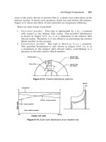
1. Free-vortex prewhirl. This type is represented by r
1
V
1
constant
with respect to the inducer inlet radius. This prewhirl distribution
is shown in Figure 6-13. V
1
is at a minimum at the inducer inlet
shroud radius. Therefore, it is not effective in decreasing the relative
Mach number in this manner.
2. Forced-vortex prewhirl. This type is shown as V
1
=r
1
constant.
This prewhirl distribution is also shown in Figure 6-14. V
1
is at
a maximum at the inducer inlet shroud radius, contributing to a
decrease in the inlet relative Mach number.
Figure 6-13. Prewhirl distribution patterns.
Figure 6-14. Euler work distribution at an impeller exit.
Centrifugal Compressors 231
//INTEGRA/B&H/GTE/FINAL (26-10-01)/CHAPTER 6.3D ± 232 ± [219±274/56] 29.10.2001 3:59PM
3. Control-vortex prewhirl. This type is represented by V
1
AR
1
B=r
1
, where A and B are constants. This equation shows the first type
with A 0, B T 0, and the second type with B 0, A T 0.
Euler work distributions at an impeller exit, with respect to the impeller
width, are shown in Figure 6-14. From Figure 6-14, the prewhirl distribution
should be made not only from the relative Mach number at the inducer inlet
shroud radius, but also from Euler work distribution at the impeller exit.
Uniform impeller exit flow conditions, considering the impeller losses, are
important factors in obtaining good compressor performance.
Impeller
An impeller in a centrifugal compressor imparts energy to a fluid. The
impeller consists of two basic components: (1) an inducer like an axial-flow
rotor, and (2) the radial blades where energy is imparted by centrifugal force.
Flow enters the impeller in the axial direction and leaves in the radial direc-
tion. The velocity variations from hub to shroud resulting from these changes
in flow directions complicate the design procedure for centrifugal compres-
sors. C.H. Wu has presented the three-dimensional theory in an impeller, but
it is difficult to solve for the flow in an impeller using the previous theory
without certain simplified conditions. Others have dealt with it as a quasi-
three-dimensional solution. It is composed of two solutions, one in the
meridional surface (hub-to-shroud), and the other in the stream surface of
revolution (blade-to-blade). These surfaces are illustrated in Figure 6-15.
By the application of the previous method using a numerical solution to
the complex flow equations, it is possible to achieve impeller efficiencies of
more than 90%. The actual flow phenomenon in an impeller is more com-
plicated than the one calculated. One example of this complicated flow is
shown in Figure 6-16. The stream lines observed in Figure 6-16 do not cross,
but are actually in different planes observed near the shroud. Figure 6-17
shows the flow in the meridional plane with separation regions at the inducer
section and at the exit.
Experimental studies of the flow within impeller passages have shown that
the distribution of velocities on the blade surfaces are different from the
distributions predicted theoretically. It is likely that the discrepancies
between theoretical and experimental results are due to secondary flows
from pressure losses and boundary-layer separation in the blade passages.
High-performance impellers should be designed, when possible, with the aid
of theoretical methods for determining the velocity distributions on the
blade surfaces.
232 Gas Turbine Engineering Handbook
//INTEGRA/B&H/GTE/FINAL (26-10-01)/CHAPTER 6.3D ± 233 ± [219±274/56] 29.10.2001 3:59PM
Examples of the theoretical velocity distributions in the impeller blades
of a centrifugal compressor are shown in Figure 6-18. The blades should
be designed to eliminate large decelerations or accelerations of flow in the
impeller that lead to high losses and separation of the flow. Potential flow
solutions predict the flow well in regions away from the blades where
Figure 6-15. Two-dimensional surface for a flow analysis.
Figure 6-16. Flow map of impeller plane.
Centrifugal Compressors 233
//INTEGRA/B&H/GTE/FINAL (26-10-01)/CHAPTER 6.3D ± 234 ± [219±274/56] 29.10.2001 3:59PM
boundary-layer effects are negligible. In a centrifugal impeller the viscous
shearing forces create a boundary layer with reduced kinetic energy. If the
kinetic energy is reduced below a certain limit, the flow in this layer becomes
stagnant, then it reverses.
Figure 6-17. Flow map as seen in meridional plane.
234 Gas Turbine Engineering Handbook
//INTEGRA/B&H/GTE/FINAL (26-10-01)/CHAPTER 6.3D ± 235 ± [219±274/56] 29.10.2001 3:59PM
Figure 6-18. Velocity profiles through a centrifugal compressor.
Centrifugal Compressors 235
//INTEGRA/B&H/GTE/FINAL (26-10-01)/CHAPTER 6.3D ± 236 ± [219±274/56] 29.10.2001 3:59PM
Inducer
The function of an inducer is to increase the fluid's angular momentum
without increasing its radius of rotation. In an inducer section the blades
bend toward the direction of rotation as shown in Figure 6-19. The inducer
is an axial rotor and changes the flow direction from the inlet flow angle to
the axial direction. It has the largest relative velocity in the impeller and, if
not properly designed, can lead to choking conditions at its throat as shown
in Figure 6-19.
There are three forms of inducer camber lines in the axial direction. These
are circular arc, parabolic arc, and elliptical arc. Circular arc camber lines
are used in compressors with low pressure ratios, while the elliptical arc
produces good performance at high pressure ratios where the flow has
transonic mach numbers.
Figure 6-19. Inducer centrifugal compressor.
236 Gas Turbine Engineering Handbook
//INTEGRA/B&H/GTE/FINAL (26-10-01)/CHAPTER 6.3D ± 237 ± [219±274/56] 29.10.2001 3:59PM
Because of choking conditions in the inducer, many compressors incor-
porate a splitter-blade design. The flow pattern in such an inducer section
is shown in Figure 6-20a. This flow pattern indicates a separation on the
suction side of the splitter blade. Other designs include tandem inducers. In
tandem inducers the inducer section is slightly rotated as shown in Figure
6-20b. This modification gives additional kinetic energy to the boundary,
which is otherwise likely to separate.
Centrifugal Section of an Impeller
The flow in this section of the impeller enters from the inducer section and
leaves the impeller in the radial direction. The flow in this section is not com-
pletely guided by the blades, and hence the effective fluid outlet angle does
not equal the blade outlet angle.
To account for flow deviation (which is similar to the effect accounted for
by the deviation angle in axial-flow machines), the slip factor is used:
V
2
V
2I
6-8
(a) (b)
Figure 6-20. Impeller channel flow.
Centrifugal Compressors 237
//INTEGRA/B&H/GTE/FINAL (26-10-01)/CHAPTER 6.3D ± 238 ± [219±274/56] 29.10.2001 3:59PM
where V
2
is the tangential component of the absolute exit velocity with a
finite number of blades, and V
2I
is the tangential component of the
absolute exit velocity, if the impeller were to have an infinite number of
blades (no slipping back of the relative velocity at outlet).
With radial blades at the exit,
V
2
U
2
6-9
Flow in a rotating impeller channel (blade passage) will be a vector sum of
flow with the impeller stationary and the flow due to rotation of the impeller
as seen in Figure 6-21.
In a stationary impeller, the flow is expected to follow the blade shape and
exit tangentially to it. A high adverse pressure gradient along the blade
passage and subsequent flow separation are not considered to be general
possibilities.
Inertia and centrifugal forces cause the fluid elements to move closer to
and along the leading surface of the blade toward the exit. Once out of the
blade passage, where there is no positive impelling action present, these fluid
elements slow down.
Causes of Slip in an Impeller
The definite cause of the slip phenomenon that occurs within an impeller
is not known. However, some general reasons can be used to explain why the
flow is changed.
Figure 6-21. Forces and flow characteristics in a centrifugal compressor.
238 Gas Turbine Engineering Handbook
//INTEGRA/B&H/GTE/FINAL (26-10-01)/CHAPTER 6.3D ± 239 ± [219±274/56] 29.10.2001 3:59PM
Coriolis circulation. Because of the pressure gradient between the walls
of two adjacent blades, the Coriolis forces, the centrifugal forces, and the
fluid follow the Helmholtz vorticity law. The combined gradient that results
causes a fluid movement from one wall to the other and vice versa. This
movement sets up circulation within the passage as seen in Figure 6-22.
Because of this circulation, a velocity gradient results at the impeller exit
with a net change in the exit angle.
Boundary-layer development. The boundary layer that develops
within an impeller passage causes the flowing fluid to experience a smaller
exit area as shown in Figure 6-23. This smaller exit is due to small flow
(if any) within the boundary layer. For the fluid to exit this smaller area,
its velocity must increase. This increase gives a higher relative exit velocity.
Figure 6-22. Coriolis circulation.
Figure 6-23. Boundary-layer development.
Centrifugal Compressors 239
//INTEGRA/B&H/GTE/FINAL (26-10-01)/CHAPTER 6.3D ± 240 ± [219±274/56] 29.10.2001 3:59PM
Since the meridional velocity remains constant, the increase in relative
velocity must be accompanied with a decrease in absolute velocity.
Although it is not a new approach, boundary-layer control is being used
more than ever before. It has been used with success on airfoil designs when
it has delayed separation, thus giving a larger usable angle of attack. Control
of the flow over an airfoil has been accomplished in two ways: by using slots
through the airfoil and by injecting a stream of fast-moving air.
Separation regions are also encountered in the centrifugal impeller as
shown previously. Applying the same concept (separation causes a loss in
efficiency and power) reduces and delays their formation. Diverting the slow-
moving fluid away lets the separation regions be occupied by a faster stream
of fluid, which reduces boundary-layer build-up and thus decreases separation.
To control the boundary layer in the centrifugal impeller, slots in the
impeller blading at the point of separation are used. To realize the full
capability of this system, these slots should be directional and converging
in a cross-sectional area from the pressure to the suction sides as seen in
Figure 6-24. The fluid diverted by these slots increases in velocity and
attaches itself to the suction sides of the blades. This results in moving the
separation region closer to the tip of the impeller, thus reducing slip and
losses encountered by the formation of large boundary-layer regions. The
slots must be located at the point of flow separation from the blades. Experi-
mental results indicate improvement in the pressure ratio, efficiency, and
surge characteristics of the impeller as seen in Figure 6-24.
Leakage. Fluid flow from one side of a blade to the other side is referred
to as leakage. Leakage reduces the energy transfer from impeller to fluid and
decreases the exit velocity angle.
Number of vanes. The greater the number of vanes, the lower the vane
loading, and the closer the fluid follows the vanes. With higher vane load-
ings, the flow tends to group up on the pressure surfaces and introduces a
velocity gradient at the exit.
Vane thickness. Because of manufacturing problems and physical
necessity, impeller vanes are thick. When fluid exits the impeller, the vanes
no longer contain the flow, and the velocity is immediately slowed. Because
it is the meridional velocity that decreases, both the relative and absolute
velocities decrease, changing the exit angle of the fluid.
A backward-curved impeller blade combines all these effects. The exit
velocity triangle for this impeller with the different slip phenomenon changes
is shown in Figure 6-25. This triangle shows that actual operating conditions
are far removed from the projected design condition.
240 Gas Turbine Engineering Handbook
//INTEGRA/B&H/GTE/FINAL (26-10-01)/CHAPTER 6.3D ± 241 ± [219±274/56] 29.10.2001 3:59PM
Several empirical equations have been derived for the slip factor (see
Figure 6-26). These empirical equations are limited. Two of the more
common slip factors are presented here.
Stodola Slip Factor
The second Helmholtz law states that the vorticity of a frictionless fluid
does not change with time. Hence, if the flow at the inlet to an impeller is
irrotational, the absolute flow must remain irrotational throughout the
impeller. As the impeller has an angular velocity !, the fluid must have an
angular velocityÐ! relative to the impeller. This fluid motion is called the
relative eddy. If there were no flow through the impeller, the fluid in the
Figure 6-24. Percent design flowÐlaminar flow control in a centrifugal com-
pressor.
Centrifugal Compressors 241
//INTEGRA/B&H/GTE/FINAL (26-10-01)/CHAPTER 6.3D ± 242 ± [219±274/56] 29.10.2001 3:59PM
Figure 6-25. Effect on exit velocity triangles by various parameters.
Figure 6-26. Various slip factors as a function of the flow coefficient.
242 Gas Turbine Engineering Handbook
//INTEGRA/B&H/GTE/FINAL (26-10-01)/CHAPTER 6.3D ± 243 ± [219±274/56] 29.10.2001 3:59PM
impeller channels would rotate with an angular velocity equal and opposite
to the impeller's angular velocity.
To approximate the flow, Stodola's theory assumes that the slip is due to
the relative eddy. The relative eddy is considered as a rotation of a cylinder
of fluid at the end of the blade passage at an angular velocity ofÐ! about its
own axis. The Stodola slip factor is given by
1 À
Z
1 À
sin
2
V
m2
cot
2
U
2
P
T
T
R
Q
U
U
S
6-10
where:
2
the blade angle
Z the number of blades
V
m2
the meridional velocity
U
2
blade tip speed.
Calculations using this equation have been found to be lower than experi-
mental values.
Stanitz Slip Factor
Stanitz calculated blade-to-blade solutions for eight impellers and
concluded that for the range of conditions covered by the solutions, U is
a function of the number of blades (Z), and the blade exit angle (
2
)is
approximately the same whether the flow is compressible or incompressible
1 À
0:63
Z
1 À
1
W
m2
U
2
cot
2
P
R
Q
S
6-11
Stanitz's solutions were for =4 <
2
<=2. This equation compares well
with experimental results for radial or near-radial blades.
Diffusers
Diffusing passages have always played a vital role in obtaining good
performance from turbomachines. Their role is to recover the maximum
possible kinetic energy leaving the impeller with a minimum loss in total
pressure. The efficiency of centrifugal compressor components has been
steadily improved by advancing their performance. However, significant
Centrifugal Compressors 243
//INTEGRA/B&H/GTE/FINAL (26-10-01)/CHAPTER 6.3D ± 244 ± [219±274/56] 29.10.2001 3:59PM
further improvement in efficiency will be gained only by improving the
pressure recovery characteristics of the diffusing elements of these machines,
since these elements have the lowest efficiency.
The performance characteristics of a diffuser are complicated functions of
diffuser geometry, inlet flow conditions, and exit flow conditions. Figure 6-27
Figure 6-27. Geometric classification of diffusers.
244 Gas Turbine Engineering Handbook
//INTEGRA/B&H/GTE/FINAL (26-10-01)/CHAPTER 6.3D ± 245 ± [219±274/56] 29.10.2001 3:59PM
shows typical diffusers classified by their geometry. The selection of an
optimum channel diffuser for a particular task is difficult, since it must be
chosen from an almost infinite number of cross-sectional shapes and wall
configurations. In radial and mixed-flow compressors the requirement of
high performance and compactness leads to the use of vaned diffusers as
shown in Figure 6-28. Figure 6-28 also shows the flow regime of a vane-
island diffuser.
Matching the flow between the impeller and the diffuser is complex
because the flow path changes from a rotating system into a stationary
one. This complex, unsteady flow is strongly affected by the jet-wake of
the flow leaving the impeller, as seen in Figure 6-29. The three-dimensional
boundary layers, the secondary flows in the vaneless region, and the flow
separation at the blades also affects the overall flow in the diffuser.
The flow in the diffuser is usually assumed to be of a steady nature to
obtain the overall geometric configuration of the diffuser. In a channel-type
diffuser the viscous shearing forces create a boundary layer with reduced
kinetic energy. If the kinetic energy is reduced below a certain limit, the flow
in this layer becomes stagnant and then reverses. This flow reversal causes
Figure 6-28. Flow regions of the vaned diffuser.
Centrifugal Compressors 245
//INTEGRA/B&H/GTE/FINAL (26-10-01)/CHAPTER 6.3D ± 246 ± [219±274/56] 29.10.2001 3:59PM
separation in a diffuser passage, which results in eddy losses, mixing losses,
and changed-flow angles. Separation should be avoided or delayed to
improve compressor performance.
The high-pressure-ratio centrifugal compressor has a narrow yet stable
operating range. This operating range is due to the close proximity of the
surge and choke flow limits. The word ``surge'' is widely used to express
unstable operation of a compressor. Surge is the flow breakdown period
during unstable operation. The unsteady flow phenomena during the onset
of surge in a high-pressure-ratio centrifugal compressor causes the mass flow
throughout the compressor to oscillate during supposedly ``stable'' operations.
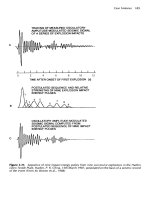
The throat pressure in the diffuser increases during the precursor period
up to collector pressure P
col
at the beginning of surge. All pressure traces
(except plenum pressure) suddenly drop at the surge point. The sudden
change of pressure can be explained by the measured occurrence of backflow
from the collector through the impeller during the period between the two
sudden changes.
Figure 6-29. Jet-wake flow distribution from an impeller.
246 Gas Turbine Engineering Handbook
//INTEGRA/B&H/GTE/FINAL (26-10-01)/CHAPTER 6.3D ± 247 ± [219±274/56] 29.10.2001 3:59PM
Scroll or Volute
The purpose of the volute is to collect the fluid leaving the impeller or
diffuser, and deliver it to the compressor outlet pipe. The volute has an
important effect on the overall efficiency of the compressor. Volute design
embraces two schools of thought. First, the angular momentum of the flow
in the volute is constant, neglecting any friction effects. The tangential
velocity V
5
is the velocity at any radius in the volute. The following equa-
tion shows the relationship if the angular momentum is held constant
V
5
r constant K 6-12
Assuming no leakage past the tongue and a constant pressure around the
impeller periphery, the relationship of flow at any section Q
to the overall
flow in the impeller Q is given by
Q
2
Q 6-13
Thus, the area distribution at any section can be given by the following
relationship:
A
Qr Â
2
Â
L
K
6-14
where:
r radius to the center of gravity
L volume width
Second, design the volute by assuming that the pressure and velocity are
independent of . The area distribution in the volute is given by
A
K
Q
V
5
2
6-15
To define the volute section at a given , the shape and area of the section
must be decided. Flow patterns in various types of volute are shown in
Figure 6-30. The flow in the asymmetrical volute has a single-vortex instead
of the double-vortex in the symmetrical volute. Where the impeller is dis-
charging directly into the volute, it is better to have the volute width larger
than the impeller width. This enlargement results in the flow from the
Centrifugal Compressors 247
//INTEGRA/B&H/GTE/FINAL (26-10-01)/CHAPTER 6.3D ± 248 ± [219±274/56] 29.10.2001 3:59PM
impeller being bounded by the vortex generated from the gap between the
impeller and the casing.
At flows different from design conditions, there exists a circumferential
pressure gradient at the impeller tip and in the volute at a given radius.
Figure 6-30. Flow patterns in volute.
248 Gas Turbine Engineering Handbook
//INTEGRA/B&H/GTE/FINAL (26-10-01)/CHAPTER 6.3D ± 249 ± [219±274/56] 29.10.2001 3:59PM
At low flows, the pressure rises with the peripheral distance from the volute
tongue. At high flows, the pressure falls with distance from the tongue. This
condition results because near the tongue the flow is guided by the outer wall
of the passage. The circumferential pressure gradients reduce efficiency away
from the design point. Nonuniform pressure at the impeller discharge results
in unsteady flows in the impeller passage, causing flow reversal and separ-
ation in the impeller.
Centrifugal Compressor Performance
Calculating the performance of a centrifugal compressor in both design and
off-design conditions requires a knowledge of various losses encountered
in a centrifugal compressor.
The accurate calculation and proper evaluation of losses within a centri-
fugal compressor is as important as the calculation of the blade-loading para-
meters. If the proper parameters are not controlled, efficiency decreases. The
evaluation of various losses is a combination of experimental results and theory.
The losses are divided into two groups: (1) losses encountered in the rotor, and
(2) losses encountered in the stator.
A loss is usually expressed as a loss of heat or enthalpy. A convenient way
to express them is in a nondimensional manner with reference to the exit
blade speed. The theoretical total head available (q
tot
) is equal to the head
available from the energy equation
q
th
1
U
2
2
U
2
V
2
À U
1
V
1
6-16
plus the head, which is lost because of disc friction (Áq
df
) and resulting from
any recirculation (Áq
rc
) of the air back into the rotor from the diffuser
q
tot
q
th
Áq
df
Áq
rc
6-17
The adiabatic head that is actually available at the rotor discharge is equal
to the theoretical head minus the heat from the shock in the rotor (Áq
sh
), the
inducer loss (Áq
in
), the blade loadings (Áq
bl
), the clearance between the
rotor and the shroud (Áq
c
), and the viscous losses encountered in the flow
passage (Áq
sf
)
q
ia
q
th
À Áq
in
À Áq
sh
À Áq
bl
À Áq
c
À Áq
sf
6-18
Centrifugal Compressors 249
//INTEGRA/B&H/GTE/FINAL (26-10-01)/CHAPTER 6.3D ± 250 ± [219±274/56] 29.10.2001 3:59PM
Therefore, the adiabatic efficiency in the impeller is
imp
q
ia
q
tot
6-19
The calculation of the overall stage efficiency must also include losses
encountered in the diffuser. Thus, the overall actual adiabatic head attained
will be the actual adiabatic head of the impeller minus the head losses
encountered in the diffuser from wake caused by the impeller blade (Áq
w
),
the loss of part of the kinetic head at the exit of the diffuser (Áq
ed
), and
the loss of head from frictional forces (Áq
osf
) encountered in the vaned or
vaneless diffuser space
q
oa
q
ia
À Áq
w
À Áq
ed
À Áq
osf
6-20
The overall adiabatic efficiency in an impeller is given by the following
relationship:
ov
q
oa
q
tot
6-21
The individual losses can now be computed. These losses are broken up
into two categories: (1) losses in the rotor, and (2) losses in the diffuser.
Rotor Losses
Rotor losses are divided into the following categories:
Shock in rotor losses. This loss is due to shock occurring at the rotor
inlet. The inlet of the rotor blades should be wedgelike to sustain a weak
oblique shock, and then gradually expanded to the blade thickness to avoid
another shock. If the blades are blunt, a bow shock will result, causing the
flow to detach from the blade wall and the loss to be higher.
Incidence loss. At off-design conditions, flow enters the inducer at an
incidence angle that is either positive or negative, as shown in Figure 6-31.
A positive incidence angle causes a reduction in flow. Fluid approaching
a blade at an incidence angle suffers an instantaneous change of velocity at
the blade inlet to comply with the blade inlet angle. Separation of the blade
can create a loss associated with this phenomenon.
Disc friction loss. This loss results from frictional torque on the back
surface of the rotor as seen in Figure 6-32. This loss is the same for a given
250 Gas Turbine Engineering Handbook
//INTEGRA/B&H/GTE/FINAL (26-10-01)/CHAPTER 6.3D ± 251 ± [219±274/56] 29.10.2001 3:59PM
size disc whether it is used for a radial-inflow compressor or a radial-inflow
turbine. Losses in the seals, bearings, and gear box are also lumped in with
this loss, and the entire loss can be called an external loss. Unless the gap is
of the magnitude of the boundary layer, the effect of the gap size is negli-
gible. The disc friction in a housing is less than that on a free disc due to the
existence of a ``core,'' which rotates at half the angular velocity.
Diffusion-blading loss. This loss develops because of negative velocity
gradients in the boundary layer. Deceleration of the flow increases the
boundary layer and gives rise to separation of the flow. The adverse pressure
gradient that a compressor normally works against increases the chances of
separation and causes significant loss.
Figure 6-31. Inlet velocity triangles at nonzero incidents.
Centrifugal Compressors 251
//INTEGRA/B&H/GTE/FINAL (26-10-01)/CHAPTER 6.3D ± 252 ± [219±274/56] 29.10.2001 3:59PM
Clearance loss. When a fluid particle has a translatory motion relative
to a noninertial rotating coordinate system, it experiences the Coriolis force.
A pressure difference exists between the driving and trailing faces of an
impeller blade caused by Coriolis acceleration. The shortest and least resis-
tant path for the fluid to flow and neutralize this pressure differential is
provided by the clearance between the rotating impeller and the stationary
casing. With shrouded impellers, such a leakage from the pressure side to the
suction side of an impeller blade is not possible. Instead, the existence of a
pressure gradient in the clearance between the casing and the impeller
shrouds, predominant along the direction shown in Figure 6-33, accounts
for the clearance loss. Tip seals at the impeller eye can reduce this loss
considerably.
This loss may be quite substantial. The leaking flow undergoes a large
expansion and contraction caused by temperature variation across the clear-
ance gap that affects both the leaking flow and the stream into which it
discharges.
Skin friction loss. Skin friction loss is the loss from the shear forces
on the impeller wall caused by turbulent friction. This loss is determined by
considering the flow as an equivalent circular cross section with a hydraulic
diameter. The loss is then computed based on well-known pipe flow pressure
loss equations.
Figure 6-32. Secondary flow at the back of an impeller.
252 Gas Turbine Engineering Handbook
//INTEGRA/B&H/GTE/FINAL (26-10-01)/CHAPTER 6.3D ± 253 ± [219±274/56] 29.10.2001 3:59PM
Stator Losses
Recirculating loss.
This loss occurs because of backflow into the impel-
ler exit of a compressor and is a direct function of the air exit angle. As the
flow through the compressor decreases, there is an increase in the absolute
flow angle at the exit of the impeller as seen in Figure 6-34. Part of the fluid is
recirculated from the diffuser to the impeller, and its energy is returned to
the impeller.
Wake-mixing loss. This loss is from the impeller blades, and it causes
a wake in the vaneless space behind the rotor. It is minimized in a diffuser,
which is symmetric around the axis of rotation.
Figure 6-33. Leakage affecting clearance loss.
Centrifugal Compressors 253
//INTEGRA/B&H/GTE/FINAL (26-10-01)/CHAPTER 6.3D ± 254 ± [219±274/56] 29.10.2001 3:59PM
Vaneless diffuser loss. This loss is experienced in the vaneless diffuser
and results from friction and the absolute flow angle.
Vaned diffuser loss. Vaned diffuser losses are based on conical diffuser
test results. They are a function of the impeller blade loading and the vaneless
space radius ratio. They also take into account the blade incidence angle and
skin friction from the vanes.
Exit loss. The exit loss assumes that one-half of the kinetic energy leav-
ing the vaned diffuser is lost.
Losses are complex phenomena and as discussed here are a function of
many factors, including inlet conditions, pressure ratios, blade angles, and
flow. Figure 6-35 shows the losses distributed in a typical centrifugal stage of
pressure ratio below 2:1 with backward-curved blades. This figure is only a
guideline.
Compressor Surge
A plot showing the variation of total pressure ratio across a compressor as
a function of the mass flow rate through it at various speeds is known as a
performance map. Figure 6-36 shows such a plot.
The actual mass flow rates and speeds are corrected by factors (
p
=)
and (1=
p
), respectively, to account for variation in the inlet conditions of
temperature and pressure. The surge line joins the different speed lines where
Figure 6-34. Recirculating loss.
254 Gas Turbine Engineering Handbook
//INTEGRA/B&H/GTE/FINAL (26-10-01)/CHAPTER 6.3D ± 255 ± [219±274/56] 29.10.2001 3:59PM
the compressor's operation becomes unstable. A compressor is in ``surge''
when the main flow through the compressor reverses its direction and flows
from the exit to the inlet for short time intervals. If allowed to persist, this
unsteady process may result in irreparable damage to the machine. Lines
of constant adiabatic efficiency (sometimes called efficiency islands) are also
plotted on the compressor map. A condition known as ``choke'' or ``stone
walling'' is indicated on the map, showing the maximum mass flow rate
possible through the compressor at that operating speed.
Compressor surge is a phenomenon of considerable interest, yet it is not
fully understood. It is a form of unstable operation and should be avoided in
both design and operation. Surge has been traditionally defined as the lower
limit of stable operation in a compressor and involves the reversal of flow.
This reversal of flow occurs because of some kind of aerodynamic instability
within the system. Usually a part of the compressor is the cause of the
aerodynamic instability, although it is possible that the system arrangement
could be capable of augmenting this instability. Figure 6-36 shows a typical
Figure 6-35. Losses in a centrifugal compressor.
Centrifugal Compressors 255