flame safeguard control phần 8 pot
Bạn đang xem bản rút gọn của tài liệu. Xem và tải ngay bản đầy đủ của tài liệu tại đây (1.21 MB, 37 trang )
SAIL
SWITCHES
Honeywell sail switches
(Fig.
T7) are used in flame A small metal sail, mounted
on
a pivOI, 9Klends
inlolhe
safeguard
applications
to
prove
combustion
airflow
before
air stream. Mechanical linkage
transmits
mol
ion
of
the sail
1I1OJhloft
ar.d
while
the
burner
is running.
They
can
also
be
to a switch. The switch makes
or
breaks when the airflow
used in air ducls
to
assure that a furnace
is
supplying
reaches a speCified velocity. The switch can be used
in
ena,ugh
warm
air:
line or low
voltage
circuits.
Honeywell sail
switches
available
for
use in name safe-
guard
systems
are
listed in Table
VI
al
the end
of
the sec-
tion. Table
VI
includes switching action, operating air
velocity and direction, sail size and malerial, and special
applications. For further Information, refer fa
the
Instruc-
tion
sheets
tor
the
sail
switches.
54J7A,e;
SU1A
FIG.
77-HONEYWU~
SAIL
SWITCHES.
TABLE
VI-SUMMARY
OF HONEYWELL SAIL SWITCHES
SWITCHING
ACTION
OPERATING
AIR
VELOCITY
SAIL
SIZE
DIRECTION
OF
AIRFLOW
ON
INCREASING
FEET PER
METRES
PER
Mllll-
TO
SAil
SPECIAL
MODELS
AIR
VELOCITY
MINUTE
SECOND
INCHES
METRES
ACTUATE
MArl
APPLICATIONS
SPSI
mercury
000
3.05
5 x
4-1/2;1
127x
114
S43A
switcn.
maq~
1000
5.1
2 x 5-1/2
51
x 140
left
to
Right
1000
5.1
4-1/2 x 5
114x
127
Gas-fired
000 305
2·11/16x
7-1/2·
68 x
191
uoil
neal8f~
S43.
apff
mercurot 1000
5.1
2 x 5-1/2
51
x 140
Rigllt
to
lett.
S1ee1
IU1d
air
swrtr;ll.
makE\S
1000
5.1
2-11/16 x 7·1/2
68
x
191
conditioning
1000
5.1
4-1/2 X5
114xl27
., ".
1250
'A
4-1/2 x 5
114x127
R~L
(Upward
b)
S43D
liPS'!
mercurot 1000
5.1
2 x 5-1/2
51
x 140
Right
'0
lett
swttctl.
breaks
5437A
spst snap-acting 1900
9.6
'"
25 x 76
switch, makes
950
4.8
H12x4
38 x 102
S437B"
spst snap-acting
switch, makes
1900
1000
9.6
5.1
1 "
1.5 x 3.8
25 x 76
38,96
t"orimntal
d
AJumi· Farm crop
spdt snap-acling
1900
g,
'"
25x
76
eom
drot
ers
S837A
switch; one set
makes. one set
2200 11.2 1 x 2-1/2
25'64
breaks
a Forward bent eail.
b Adjustable
to
aetlJale
on
upwarr:i
airlDw (t:lr venical
dL.Ct
ITloI.Jnling).
"
same
a9
5437A
axcept wiIhout case and COIi'llf.
d
AJso
oparates
lor
upward
air1k:lW,
but operating air
118locitf
chantles.
257
71-97558-1
,
~.'
S43 SAIL SWITCHES
S43 Sail
Switches
are especially suited
for
use with
gas-firacl unit heaters
and
air
conditioning systems. All
models have a steel
sail
which
actuates
an
sps.I
mercury
switJ;h.
Models are available
10
actuate at air veklCllies
at
600,1000, or 12501eel
per
minute
[3.05, 5.1,
or
6.4 metres
per second]. Several
sail
sizes are available
10
accommo-
date various sizes
of
air duels. Models are available for
usa in horizontal
or
va/lical duelS,
and
to
actuate
for
any
direction
of
airflow except downward.
The.switCh
iN
!HE
S43A
or
B modelS
makes
on
increas·
lnQ air velocity; the switch in the S43D
breales.
S43A med-
els
3r~'
dasigrted
10
operate in airflow !rom lett
10
right
(lOOking
allha
face
oflhe
switch
so
the label can
be
read).
S43B
and D
models
operate in airtlow from
rl""llo
left.
One
S43B
model
is
adjustable
10
operate in
upwaId
air110w
"E"cu,,~
lwPTCN
L
:~~_r CONOU"
CONNECT'ON
SCREw
TER"'NAL5
(2)
FIG.
78-
S43
SAIL
SWITCH
WITH
COVER
REMOVEO.
5437, S637
SAIL
SWITCHES
5437
and
5637
sail
Swilches
are especially suited for
use in larm
crop
dryers.
AU
models
have
an
aluminum sail
whiCh actuates a
MICRO
SWITCH
snap-acting
switch.
5437 models have
an
$pSI
switch; 5637 models have ",n
spdt switch. Models with
standard
size sails
(1
x 3 inches
[25.4 x 76.2
mmjj
actuate at
an
air velocity at
'900
faet per
minute (9.6 metres
per
second) with the differential set at
its minimum value.
They
acluate at 2250 fee! per minute
[11.4 metres
per
second] with the differential
at
its maxi-
mum value. Other sail sizes result in different operating air
velocllies (see Table
VI). All models are designed to cper·
ate In a
horizontal
airflow;
lhey
wIll also cperale in an
u,r
ward
airflow, but the
cperaling
air velocity will change.
The
5437B
is
the same as the
5437A
except that
it
does
not
have a case
and
caver. In
both
models,
lhe
swilch
makes
on increasing air velocity (Fig.
79).
In the
5637
A, one set
of
contacts makes
(R
to
B)
and
the other
set
breaks
(R
10
IN)
on
increasing
air
velocity (Fig. 80). The
normally
cpen
contact enerQizes the load when the air
ve-
loCity is great enough,
and
the normally closecl contact en-
ergizes an alarm
when
the air velocity
drops
off.
tror vertical ducts).
The S43 Sail
Switch
may
be
used
on
several different
types
Of
applicaticns; therefore, the location
and
Installa-
tion will depend
on
the speCifiC jc:tl. The case is usually
mounled
on
the side
ot
a
ducl
or
unil
healer in a vertical
(upright) posilion. The top
of
the case must
be
level
lor
pTq:lElr
cperalion
of
the
mercury
swilch. The sail should
be
in the direct path
of
the airstream where the movement
01
the air will
be
unrestricted,
and
must
be
free to return. to the
-down"
position
under
its
own
weight. Wiring is routed
lhrough
the conduil
oullel
in the
bottom
of
the case,
and
tnen connected to the 2
screw
terminals on the terminal
block inside the case
(FiQ.
78).
SoUJA
OR
B
"
& M""l<E5
01'1
'I'ICIlE""5'I'IG AlII.
VELOCITY
•
A
LOAO
FIG.
79-S437A
OR B
INTERNAL
SCHEMATIC.
5637""
•
,
TO
COMMON
TO
ALAR~
LOAO
un.
FIG.
80-S637A
INTERNAL
SCHEMATIC.
The
5437
or
5637
should
be
located
so
that the sail is
in
the direct
path
Of
an unrestricted airstream. It cperates
basI in a horizontal duct. In a vertical duct, the effect
of
gravity
on
the linkage changes
lhe
operatil"lQ painl. Wiring
is
rouled
thrDLlQh
the
knockouts
in each
end
of
the case,
ilJ"Id
then connected to the screw terminals
on
the switch
inside the case (Fig. 81).
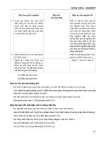
The differential
on
an
S437A,B
or
5637A
sail
Switch
can
be
adjusted by
lurning
the differen.tial setting dial (Fig.
81). The dial is
marked
with the
lellers
A, B,
C,
and 0 to
indicate relative differentials from a
minimum
of
550 fpm
(feet per minute) [2.8 metres
per
second, or m/s] to a maxi-
25.
~:'<oc~ours
(i)
DifFERENTIAl
SETTING
DIAl
""
FIG.
81-
S637A
SAIL
SWITCH
WITH
COVER
REMOVED.
(S437A
OR
B
IS
SIMILAR
EXCEPT
FOR
TERMINALS.)
mum
of
900 tpm [4.6 m/s). For sail switches with the stan·
dard 1 x 3 inch [25.4 x 76.2 mm] sail, a minimum setting
(p:)sition
A)
resulls in an cperating air velocily
of
1900 tpm
[9.6 m/sl (Fig.
62).
A maximum selting (positioo
OJ
results
in an
cperaling
air
velocity ot 2250 tpm [
71.4
rn/sJ.
The
switch breaks
at
1350 tpm [6.9
rTVsl
on decreasing air
velocity.
The
cperating
air velocity
and
the differential are in-
versely proportional
lo
the area
of
the sail.
Urger
sails
re-
sult
in operalion
at
lower
air velocities.
and
lhe dinerential
SPARK
IGNITER
Q624A SOLID STATE SPARK GENERATOR
The Honeywell Q624A Solid State Spark Generator
(Fig.
83) is used to ignite
gas
pilots with spark gaps up to
1/4 inch [6.6 millimelr8$]
on
commercial
or
irdustrial gas
burners. It prevents detection of the ignition sPark when
prcperly applied in a flame deteclion system using a
C7027. C7035,
or
C7044 Minipeeper Ultraviolet Flame
Detector.
The Q624A is rated
for
a 120 volt, 60 Hz power supply,
and
prOVides 60 Sparks
par
'!ieCQr1(j with a peak voltage of
15,000 volls. It
is
recommended for
use
with Ihe
RA890G,
R4795, R4126, R4127, R4140,
and
R4150 Flame
Safe-
guard
Controls.
II
is a solid state device
and
weighs only 3
pounds [1.4 kilograms] versus 8-1/2 p:xJnds l3.9 kilo-
grams} for
standard
Ignition transtonners.
The sPark generator
and
the Mlnipeeper ullraviolet
flame
deleclor
are synChronized by the 60 Hz ac supply
voltage (Fig. 84). They operate only
during
a small portion
at
the cycle (shown
by
shaded areas). The spark occurs
during
one-half
of
the cycle and the detector cperatBS dur-
ing
the opposite
hait
cycle. Thus, the tlan-e detector is
never "IOOdng·
when
there
is
a spark.
INSTALLING
THE
0624A
MOUNTlNG
The
Q624A
mounts
in
Ihe
same
space used
by
a
con·
ventional
ignilion
transformer. The
mounting
plate permits
llSO
M
,
__
MA~E
"
••
"M+
__
~'
VM
C'''~~~''''''l,
Klimo
0
Itoo
"M)
M,"'''V''
O"'[~~
n
l,
"O"lrIO
IllO
)
'''C~E''SI''<.l
,"
VELOCITY
FIG.
82-ADJUSTABLE
DIFFERENTIAL
FOR AN
S437A,B
OR
S637A
SAIL
SWITCH
(WITH
STANDARD
1 X 3
INC'"
(25.4
X 76.2
mm]
SAIL
SIZE).
decreases prc:portionately. To
Increase the cperaling air
velocity, the sail can
be trimmed uSing a hea"Y shears. If it
is cut to
one·half its original size, the cperaling air velocity
and
the differential will be dovtied.
Follow the instructions
of
lhe system manufacturer,
if
available,
or
adjust the differential ar"d/or sail size 10 suit
the requirernef1ts
of
your
awlication.
HIGH
VOlTAGE
El,.EC:TROOE
Ij'~MOlJ"'lING
PlATE
~~
~
COVER
SCREW
"
FIG.
83-
Q624A
SOLID
STATE
SPARK
GeNERATOR.
lhe use
at
the same
mounllng
holes without an
adapter
plale,
and
it may be
mounled
in
any
posillon.
259
71-97558-1
062.'"
SP"'A~
GENERATOR
Ef:lERGIZEO
IFLA"E
OlTiCTOIl
OHI
FIG.
84-
SYNCHRONIZATION
OF
A
Q624A
SOLIO
STATE
SPARK
GENERATOR
" .
AND
A
MINIPEEPER
ULTRAVIOLET
FLAME
DETECTOR.
WIRING
The voltage and frequency
of
the power
s~ly
cen
netted
to the Q624A must
be
120 volts, 60 Hz.
The
chaSSis
of
the Q624A
must
be
propfufy grounded
at
9JI
times, even
dUrlngbench testing; otherwise, the device may
bum out.
Loosen
the cover screw (Fig.
83)
and remove the cover.
Insert the 2leact.viras (NEC Class
1)
through the knockout
in the boltom
at
the cese and connect them fa the screw
terminals
on
the terminal board,
and
to the terminal strip or
wirIng
sl.Jbbase
01
the flame safeguard control (refer to
Ta-
bla VII and Fig. 85
or
86). Terminals
T1
and T2
on
the
Q624A must
be
connected to the prc:per terminals
of
the
flame
sa1ElQuard
control, as given in Table
Vll.
If the name
deteclof and the ignition transformer
are
nor properly
Con-
nected, the detector may sense ignition spark, which could
cause a hazardous condition.
TABLE
VII-WIRING
CONNECTIONS FOR THE
0624A
SOUD
STATE SPARK GENERATOR
FLAMe
SAFEGUARD
0624A
CONTROL
TER_
FLAME
SAFEGUARD
MODeL
MINAL
CONTROL
TeRMINAL
RA890G
IU1d
R4795
T1
•
T2
l2
Apprtlprlate ignition terminal
R4126
and
R4127
T,
lIS
specified
on
ptDgrarrmel'
Instruction
sheeL
T2
l2
l2
R4140
and
R4150
T1
Appropriate Igntllon terminal
lIS
speci1led
on
programmer
Il'I9tnJction
sheet.
T2
I
R~'ace
the
cover and
lighten
the cover screw.
Coo-
necl
the high voltage electrode (Fig,
83)
to the ignition
eleCtrode
on
the gas pilot bomB!. (The high
voltaQEl
eleC-
trode
may
be
a qulck-connect type,
or
it
may
have a
threaded lerminal nut, depending
on
the model
of
the
0624A.) Use Honeywell Spec No. R1061012 Ignition
ca-
ble
or
eq.Jivalen1. (This
wire
is raled at 350 F
[1T5
CJ
for
F'A
£
TER
'
BOUO
~
FEGu
RO
,,.SIDE
Qil
CO"TRO'
t
6
:£J
"
L2
T>
,,,,
T,o
TER""N"'L
C,
FL
E
SM[(],v
RD
CC"TR"'L,
UE
""'''C.",
TE
INnAv"
'C"
S,.UT
'DR
tE
,N
L
OU''''''AT'O''
8 TER""
ITR"
o~
",R'NG
~VB8"'~[
&
vS[
NH
<l"'~l
I
"'Ill'"''
,,,.
FIG.
B5-
0624A
CONNECTIONS
TO
AN
RAB90G,
R4795, R4126,
OR R4127
FLAME
SAFEGUARD
CONTROL.
n
l
TE
L50
RO
FEGVAIIO
'N~'O[
Q62
C"'''TRD'
t
&
T!
u~
6
_I",,.01l0N
TEll"'"''''
O'
F,A"E
~AF£"v"'''o
CONTROL
SEE
O
,
TE
,,,STRun,o,,
SHEET
'Oil
HR"'I"A'
OE~'G"AT'ON.
& TERM'N"'L ITRIP
DR
""RI
~uBB
n
&
VSE
Ie
",
""RING
"
FIG.
86-
Q624A
CONNECTIONS
TO AN
R4140
OR
R4150
FLAME
SAFEGUARD
CONTROL.
continuous duty, and
up
to 500 F
1260
C] for intermittent
use.
11
has
been tested t02S.ooo volts.)
The
ignition
caDle
should not exceed
15
reel [4.6 metres] in length,
CHECKOUT
OF
THE
QS24A
Aner Ihe Q624A installation
has
been compleled, the
fol1owinQ
checks should
be
made to ensure that the sys-
lem
is
working
pr~rly.
IGNITION SPARK RESPONSE TEST
The flame relay shOuld not respond lDull
in)
10
ignition
spark. To determine flame detector sensitivity to ignition
spark.
per10rm the following steps:
1.
Shut
off
lhe fuel suj:pJy to
Ihe
pilot and main fuel
valve(s) manually.
2.
Slart the
SYSlem
f:7.j
raising the controller set point or
f:7.j
pressirlQ the START button.
3. Energize
lhe
Q624A Sofid State Spark Generator
so
an ig1ition spark Is produCed between Ihe eleclrode and
ground.
4.
Check to
be
sure that ignition has
nol
occurred.
rrttere should
be
no
flame.) Repeal steps 1 through 3 until
Ihere
is
no
1lame.
5. Check the flams relay
on
Ihe
flame
saf~rd
con-
trol.
11
the relay
has
not
pulled
In.
the system is
~ralirlQ
prc:perly. Continue the cheCkout with the Pilot Turndown
Test.
6.
It the flame relay pUlis in,
stop
Ihe system,
r~ace
the
Q6.24A.
and repeat steps 2 through 5.
260
REMOTE
RESET
ASSEMBLIES
11110Z11
(FOA
AA.,o's
A,NO
A.7n·Sf
\187018
(FOA
A.I'O·S)
11876011
(FOA
A.l.0'S)
7.
Ilihe
flame relay pulls
in
after replacing the Q624A,
stop the system, replace the flame safeguard control, and
repeat steps 2 through
5.
o.
-
8.
If
the flame relay pulls
in
after replacing the name
saf8QUard control, Contact the local Honeywell branch
office.
Remole reset assemblies provide the capability
of
re-
selting the lockout (safety) switch in flame saleguard con-
trols from a remote location. All example
of
this
awlication
'IS
where the flame safeg.Jard control is located
on
an inac-
cessible roof
or
suspended from a ceiling with no catwalk.
AIlother example is where the
ftalT\El
safeguard control
is
mounted in an explosion-proot enClosure; the housing
is
secured
by
many bolts. In all
of
these
awlications,
it is dif-
licult to gel
allhe
resel buttQ1 on the
11ame
safeguard can·
lrol. so the ability to
remotely
r9S9t
lhe lockout switch is
highly desirable.
Some insurance agencies and code bodies severely
restricllhe
use
01
remale reset assemblies, If there
is
any
question, these aulhorities should
be consulted prior to in-
stallation
of
the reset assemblies,
REMOTE
RESET
COVERS
Remote reset covers are heavy
dUty
metal covers with
a remole reset assembly mounted
011
them. The cover fits
over the flame safeguard control. The remote reset as-
semtJly
consists
of
a 120 Vall, 60 Hz solenoid, with a
plunger Ihat
is
direCtly ali ,-,ed with the (esel
bullon
Q11he
ftalT\El
safeguard control. Connecled to the solenoid is a
17
inch [430 mm] length
of
2-wire, flexible Conduit, plus
19
inches [480 mm]
01
exposed, insulated leadwires. Longer
wires, spliCed to these 2 wires, are connected
10
a remote
PUSh-bulton switCh, Pressing the push-bu!lon switch ener-
gizes the solenoid and activates the plunger, The plunger
awlies
pressure to the reset
bullon
on
the flame sale-
guard control to reset the lockout (safely) switch.
Flemote reset covers available are shown
in
Fig,
87,
Honeywell part numbers are:
118701
a-for
use on R4150 Flame Safeguard
Pro-
gramming Controls.
118702B-1or use on RA890 and R4795 Flame sate-
guard Primary Controls.
198365A-for
use
on
R7795 Flame Safeguard Primary
Controls,
118760B-for
use on R4140 Flame safeg.Jard
Pro-
gramming Controls.
PILOT TURNDOWN TEST
Refer
10
the flame safeguard control )nslnJclion sheel
tor the exact procedure to
be used in performing the pilot
lurndown test.
FINAL
CHECKOUT
After other checks have been completed, restore the
system to normal operation
and
ooserve at least one
com-
plete cycle
fo
be sure
of
satisfactory burner operation.
FIG.
87-REMOTE
RESET
COVE-FIS.
261 71·97558-1
••
To Install a remote reset
CO'll8r,
loosen the screw(s) in
the
old cover
llf
there
Is
one) and remove It.
Allgl
the
sola
noid
plunger In the
new
cover with the reset button on the
flame
safeQ.JlHd
control, and
mounllhe
cover. Make sure
there
!tiar
leasl
1/4
Inch
16.5
mmj clearance
101"
the
plunger.
Then tighten the cover screw(s).
AI the deSired remOle location mount a momentary
push-bullon swilch.
The
switch must
be
rated to carry at
least
15
VA
Ohe
power
qonsu~ion
of the remote reset
solenoi9). Connecl the push.outton swilch
10 lhe solenoid
(Fig.
88).
Do
notUS&8 toggleswiteh;
if
laft in the
"on"
posi·
tion.
II
wguld
cause
the lockout switch to remain in the
"open" posilion. The solenoid plunger
of
the remote resel
assembly must disengage from the reset
bullon
on
the
flame safeguard conirol In
order
for the lockout sWitch to
ee>rTWlete
the circuli inside the control.
&
PRO.,O'
0"~ONN'C1
",AN,
ANOOV'R~OAO
PRonc·~,,~
""' I
A'
RH
".O
In.
'0T<
"Un
00"<
0'0"
_TEO
A'"
VA
In
"0
",
A'
O"'R<O
~,
O
"oLAno"
c ~
FIG.
88-
TYPICAL
HOOKUP
OF A REMOTE
RESET
ASSEMBLY.
If
addilional wire is needed to reach the push'bullon
switch, splice
it
10
the 2leadwires exlending from the
flex-
Ible conduit on the reset assembly (Fig.
B7).
Moisture-ra
siSlanl No.
'4
wire.
suilablefor
atleasf 167 F
[75
C)
If
used
with
an
RA8900r R4795 , or for
all~1194
F
190
C]
if used
with an R4140 or R4150,
is
recommended for normal
installations.
The lockout switch can
be
reset right al the flame safe-
guard control
by
pressing the
end
of the solenoid plunger,
or it CM be
reselfrom
lhe remole localion
by
presslnljlhe
remOle push-bullcn switch.
REMOTE
RESET
ASSEMBLY (PART NO.
118811A)
FOR
AN
R4138C
OR 0
This remote
Jeset
a.ssenbly
Is
very similar to the as-
sembly used
011 Ihe ramote reset covers, except thai
II
does not have a flexible conduit around its leadwlres. and
It
has asolenoid arm (Fig.
90)
which depresses lhe
JoC~oul
swllch reset bUIlDl'l
on
the R4138when the solenoid
Is
en-
ergiZed. To mount the remole reset assembly
on
an
R4138C or D Induslrial Flame safeguard Control, insert
262
the nut
and washer
00
the remote reset assembly Into lhe
hole in the chassis
just
below the
loc~out
switch
on
the
R4138 (Fig.
89). Make sure the washer engages lhe Inside
lip
of
the hole. Slide the remote reset assembly upward
(as
shown
by
the arrow)
as
far
as
it
will go. Insert the mounllng
screw and tIghten It
securely
(Fig. 90). Make sure there is a
minimum
of
1/4 Inch [6.5
rTVTI]
clearance between the sole-
noid arm and the lockout switch reset
bullon
when the
lockout swilcn
is
reset. Wiring and q:'lEIration
01
this assam·
biy is the same
as
for the remote reset covers (Fig. 68).
:,U'
HANDLE
~
-
.______LOCI<OUT
'I
~'.,:,-;-
'"'''"
,,,
r RE~QTE
~
RESET
• I ,
.,
~_\.
ASSEMIIl"
•
RAllS
r·
iJ.
I
CHASSIS
"O,-E
IN
C"ASSIS
\
NUT
AND
WAS"EIl
".,
FIG.
89-INSTALLING
A
'1BB'1A
REMOTE
RESET
ASSEMBLY
ON
AN
R4138.
LOCKOUT
SWorCH
"ESU
BUTTON
~O:~oJl
J';l! SOLENOIO
A
__
-
EMOTE
RESET
ASSEMBLV
SOLENOID
' W'RE
{2_(lLACKI
~~L
MOUNTING
CHASSIS
r
)
SCIIEW
"u
L _
FIG.
90-A
'18811A
REMOTE RESET
ASSEMBLY
INSTALLED.
INTRODUCTION
A Flame safeguard System
inclu~
all controls and
associated
de~ces
r8QJired far safe corrbustlon.
01
the
lh(ee elements required for corroustion
-fuel,
air, and
ig-
nition-fuel
is the easiest to control.
The
purpose
01
the valve train, then, is to control the
flow
of
fuel into a combustion chamber so Ihal it burns
evenly_ Even combustion conserves fuel, controls pollut-
ant by producls, and provides the right amount
of
heal
needed
for
the process.
In
addition. many
~roval
bodies such
as
Underwrit-
ers
L aOOrator(es
Inc., Factory Mufual (FMj, and Factory
in-
suranCe Association (EI.A.) issue
co::ies
for burning fuel
safely.
In this section,
we
will
COYer
the types
of
valves avail-
able
and
develop typical valva trains
to
be
used in Flame
safeguard Systems.
TYPES
OF
VALVES
There are four types
of
valves used with ffame safe-
guard
equipment. They are the Manually Operated Valve.
or
the Automatic Solenoid. Diaphragm,
and
Motorized
valves, Fig.
1.
VALVES
MANLiAL
MOTORIZED
DIAPHRAGM
RVG 1.1-1
FIG.
1-VALVES
USED WITH
FLAME
SAFEGUARD EQUIPMENT.
MANUALLY
OPERATED VALVES
Although
most
valva trains reqJlra automatic opera-
tion, the
manual
valve, Fig. 2,
still
provides corwenianl fuel
shutoff
for
temporary maintenance
or
service.
Manual
shutoff
valves are
used
in
oolh
the main
and
pi-
lot fuel lines. This valve is also called a
plug
cock because
263
it
consists
of
a tapered
plug
with a horizontal opening.
As
thEi
manually operated handle turns
thEi
plug, gas llows
through the opening.
A V5050A
FUElI
Cock is anElIElclrically interlocking plug
cock.
The V5060A, Fig. 3, has two internal1nterlock switches
that are connEicted to the Flame
safeguard
Car'llrol and
sa1ely Shutoff Valve. These switches prEivent ignition
of
the pilot
if
thEi
V5060A Valve is open. AflEir
thEi
pilot is ig-
nited, the V5D60A may
be
manually cpaned to light the
main burner.
ArlolhEir
type
of
valvEi
is the Manual Reset
safety
Shut-
off
Va)~e
commonly called a Free-hardle Valve. This
valvEi
closes automatically
in
response to Ihe Flame safe-
guard Controt, but must
be
opened
by
hand.
An
electrical
circuit holds the valve open but cannot open it
by
itself. Af-
ter
thEi
circuil is
ElnEirgized,
IhEi
valve is
~
by
hand
and remains open until
tl"lEl
circull
is
de-energized. This
PLUG
COCK
MANUAL
SHUTOFF
VALVE
o
FIG.
2-PLUG
COCK
MANUAL
SHUTOFF VALVE.
GAS
LINE
PLUGGED
GAS
FLOWING
71-97558-1
V5060A
SUPERVISORY
FUEL
COCK
FIG.
3-VS060A
SUPERVISORY
FUEL COCK.
Free Handle Val
e is
used
as the safety shutoff valve
only
In
manually ignited systems
where
the
burner
is seldom
shul down.
AUTOMATIC VALVES
SOLENOiD
VALVES
Of
the three automatic valves. the Solenoid is the sim-
plest
and
generally
lhe
least 8lCpensiv8. A controller opens
the
valve
by
running
an
electric current
through
a mag-
netic coil, Fig.
4.lh6
coil, ac1lng as a magnet,
pulls
up
the
valve disc
and
allows
the gas or
oil
10
flow.
Solenoid
action
provides fasl
CIp!:lning
and
closing limes, usually less than
one second in
models
wilhoul
a thermistor delay.
The
V4046C
Solenoid
Valve
is
Widely
used
for
safety
shutoff valves in gas
pilollines.
The
V8036
or
V4Q36,
Fig.
S,
is used in the
main
lines
of
smaJJ
to
maoum
gas
sys.
lems.
Unlike
Diaphragm
or
Motorized
Valves, the Soler
noid
is
also
used
in
,:,il
burning
systems.
Use
a V4046A,B
SOLENOID
CO"TRCl'-'-~FI
OPERATION
!-I-CDJL
VALVE
DISC
•
•
5lF!?::;:·="~=,.,
~I
SOLENOID
VALVES
FAST OPENING AND CLOSING
SMALLER
APPLICATIONS
V4QJ6,
Veal6
FIG.
S-V4Q36N8036
SOLENOID
VALVES.
for
no
heavier than No. 2
oil;
and
use a V4021A
for
heavy
oil <lWlicallons.
ALL
of
lhese are
Solanoid
valves.
DIAPHRAGM
VALVES
Diaphragm Valves, like the
DrI8
Shown in Fig.
6,
are
generally
used
on
atmosph&ric
typeo
gas
burners
10r
smooth lightoN.
These
valves have a slow
opening
and
last closing
lime
which
deperdi
on the amount
of
gas
flowing over the diaphragTl.
ThQ
valve consists
0'
a
diachraam
wifh
a weiQ!l( over
the valve seal. A small inlernal solenoid valve blocks the
gas flow
10
lhe
bleed
port.
When
the COn/roJlef is
not
camnglor
heat,
Fig
7,
the
Coil
is de energized.
The
plunger
in the three-way actuator is
In
lhe
DOWN
position, 50
lhallhe
bleed' port is closed
and
lhe
supply
port is
opeM.
Gas
1l0'NS
to
the
top
01
the
dia·
ohragm.
lhe
gas
pressure
and
the
weight
hold
the valve
closed.
DIAPHRAGM
VALVES
SLOW OPENING-FAST CL.OSING
USED ON ATMOSPHERIC GAS BURNERS
V480R
vsa
~v~
113-7
FIG.
6-V48/88
AND
V4843/B843
DIAPHRAGM
FIG.
4-S0lENOJD
OPERATION.
VALVES.
71-97558-1
264
,
PLUNGER
WEIGHT
DIAPHRAGM
"'"'
TO
~
SUPPl't/
PASSAGE
TO
BLEED
PORT
~~~PLiy :~~ :::::::~:::=~:::==·=UJR_N_fR
RVG
1]·11
VALVE
CLOSED
r~~-,GAS
PLUNGER
SUPPL
v
PASSAGE
_
OIAPh'RAGM
, "
WEIGI;tT
f
TO
BLEEO
PORT
MAIN
-
__
TO
-
GAS
J BURNER
SUPPL
VL~~~ :-::::: ~=~:::==r-
live &3-1
FIG.
7-S0LENOID
VALVE
- CLOSED.
On a call
lor
heat, Fig.
8.
Ihe controller contacts close
and
the coil is energized. This pulls the plunger to the UP
p:>silion,
opening
the
bleed
port
and
closing the sl lWly
port. The
Qas
then
bleeds
off
the
lcp
at the diaphragm, al-
lowing Ihe
Qas
pressure
'Qeiow
\0 lift the diaphragm and
open the
val
"'e.
When
aillhe
Qas
has
bled
off
the
lop
of
the diaphragn,
Ihe
valve is fully
q::lEln,
FIg.
9,
permitting
gas
flow to Ihe
main burner.
After
1M
controllar is satisfied, the proceclJre is re-
versed. The controller contacts
open so Ihal the coil is de-
-,'
energiZed. The
plunger
is released, moving \0 the DOWN
p:>silion,
FiQ.
10. This closes
lhebleed
pan
and q::lBns
the
sUJ)ply
port
so
that
gas
at;tain flows to the
lop
at the dia·
VALVE
OPENING
PLUNGER
WEIGHT
OIAPHRAGM
GAS
SUPPL
."
PASSAGE
•
TO
BLEEO
PORT
MAIN
TO
GAS
SUPPL
I.
V,.
~~: _::::,, ~,-~::;;;===.=UJR_N_f_R
,
FIG.
a-SOLENOIO
VALVE
- OPENING.
VALVE
OPEN
~:==~
GAS
PLUNGER
SUPflL
v
WEIGHT
PASSAGE
DIAPHRAGM
TO
BLEED
-"
~
PORT
MAIN
-'./
' ' ~-! JTL.O-
GAS
~
./
'
BURNER
SUPPLLy_-: _ :~:::c::=~~==:r-
FIG.
9-S0LENOID
VALVE -
FULLY
OPEN.
MAIN
VALVE
CLOSED
GAS
FIG.
10-S0LENOID
VALVE
- CLOSEO.
I:f1ragm.
As
the
prBSSlJre
alXNe the diaphragm increases,
the diaphragm dtc:ps. closing the
't/al't/e
with a posill't/Q.
snap acllon.
Diaphragm
't/al't/85
are
CJ,liet
ard
ha't/(1
a reasonably
long life.
They
are generally less expensi't/e than motor·
ized
't/al't/85.
Another
~
01
diaphragm gas
't/al't/e
is the
COI'T"biM'
tion
't/alve
(Fig.
11).
The basic q::l9falion
of
this
If8I't/e
is
the
same as already dBscrlbed, except thai it
adds
(or
corn-
billB5) other f\.lnctlons into one
't/al'tle
txxly. The
V484JIV6843B,C.L,N Valve Incorporales a single stage
pt8S8U1'8
regJrator
into
the basic dlaphraQTi
't/al't/(1
desigl.
The V4844/V8844B.C,L, N models pro't/lde
two
stage pres-
sure reg.rlation. The one
or
two slages
0'
pressure reg.rla-
tion are
used fa
prO'ollde
one
or
two staQ31iring rale control
to the burner system. The V4843I\I8843P Val't/9 pro't/lde5
a intermittent
pilol
takeoff port.
2&5
71-97558-1
FIG
11-V4843fV8843
AND
V4844fV8844
COMBJNATION
DIAPHRAGM
VALVES
MOTORIZED
VALVES
Motorized valves perform
two
runclions-satety
shut-
off and firinQ rale control.
We
will discuss each
01
the
fUnc-
tions separately.
SAFETY SHUTOFF 'vALVES
Safely shutoff valves are
usad
for large gas burners
Ihat require:
1.
tighl closeoff.
2.
accurate control
of
large MlOUnls
01
fuel.
The Honeywell family
01
Safety Shutoff Valves
\s
shown
in
FiQ.
12.
The
VSQ55
valve Is controlled by a V4055, V4062
or
1,'9055
Fluid Power Actuator,
FIQ
13, When the controller
energizes lhB vaJvt acluator, Ihl)
pump
motor and dump
solet'lOd are energized.
The
dUrrp
valve closes to prevent
ail leaking from the piston 10
Ihe
aU
reservoir. The PUm;l
pulls oil
out
of
the reservoir, and dischargas
It
into the pis-
ton
urder
prB$SUre.
The
oil pressure. In turn. forces the
valve slem
downward
to
open the valve, Finally, a limit
switchstc:ps the pump molar when
the valve is tully open.
The valve pclSition. (open
or
closed) Is indicated through
1M windows on Ihe
frO()t
and
side
01
the actuator.
When the conlroller de-enerQizes the actualor, the
dump valve opens. allowing me
oil
from
the piston
to
re-
turn to the reservoir.
The
V4Q55
actuator contains only a
dump
valve for ON-
OFF cp9ralion.
The
1/4062
OFF-lO-HI
actualor
and
V9055 mcd; dating actuator,
FiQ.
11"
alse contain a bieed
valve to control Ihe amount
of
gas
flowing
to
the
burner.
The
bleed valve
contrds
the valve stem travel stanlng at
the
low fire position,
and
continuos 10 cperate only when
lhe
aclualor
is driving
the
valve cpen.
Valva actuatols have 2
cpenlng
tirnes- 13 and
26
sec-
onds. Models with 26 second
limi"g
have a small
molar
and
Ol"lly
1 pIston
in
lhepu~.
MOdels with 13 sec()(Xj lim-
ing have a large
motor
and 2 piston pumps.
The different
kinds
of
V5055 valves are shown
in
Rg.
12. The
VSQ55D,E
are used
for
high
pressure applica·
tions, while V5055A·C are
for
low
pressure appllca:ions.
Nole
that the V4055 ON-OFF aCluator may
be
used
with any varve.
The
V4062 OFF·LO·HI and the V9055
modulating valves must
be
used only
on
the
v5055B with a
characterized guide.
HONEYWEll
AUTOMATIC
SAFfTV
SHUTOFF
VALVES
ON·OFF
lI~~ ;=o "5A
ON
OFF
•
V4055
~J1
V5055D
OFF-LO.HI HI PRESSURE
_I
aVji055B
~
CHARACTERIZED
V4061
~
._-"'t +
"'''
GUIDE
V5055E
1-4/
PRESSURE
I
'V5055C
. .
1;
~'
" j
.J
FOR
VALVE
CLOSED
__
'
INDICATION
RV~
83,';
V9055
FIG.
12-THE
HONEYWEll
FAMilY
OFSAFETV
SHUTOFF VALVES.
71·97558·1
266
V40SSA
WITH
VSOSSA
0"
RESERVOIR
-~-
ACTUAT~
PUMP
1
OR
2 PISTONSI
OP£RATOA PISTON
VAlVE
"OPEN"
INDICATION
VAlVE
"SHUT"'
INOICATION
S10M
SEAT DISC
••
G" "
FIG.
f3-CUTAWAY
VIEW OF
AV4055A
WITH A
V5055A.
V4062 AND
V9055
PUMP MOTOR ANO DUMP
VAlVE
ASSEMBlY
T
f4E
ON
0""
V40~5
HAS A DUMP
VAlVE
ONl
V-NO
BlEED
VAlVE
PUMP MOTOR
Bl
E,
0
VA.lVE
OU"'P
VAlVE
,
'
_
OUMP
VAlVE
SOlENOIO
FIG.
14-INTERNAL
VIEW OF V4062
OR
V9055.
A Characterized Guide (or skirted gJidel.
Ag.
15. has
notches
or
V's
cut into
lhe
gJide
to determine the valve
flow
characteristics. II provides a predictable relationship
between stem travel
and
gas flow.
As
the valve varies the fuel, a c:lalTp3r linked to the
valve actuator varies the
corrbJstlon
air. In this way. the
valve
ar1d
actuator
control
both
the fuel
and
air noodecl to
vary the burner firing rate.
The V4062N50SSB
and
the
V9055,iV5055B
seNe
a dual purpose as
safely
Shutoff
Valve
and
Firing Rate Control.
These
combinations
may
only be used
on
alm0scherlc
burners
where codes allow a dual fUr1ction
't'2tlve.
For other
applications a Bullerfly Valve
IS
used.
whiCh will
be
dis-
cussed laler.
CHARACTERIZED
GUIDE
FIG.
15-A
CHARACTERIZED GUIDE.
The V5055C,E valves reQlJire a valve seal overtravel in-
terlock (Fig.
16)
10
make sure the main fuel valve
is
closac!
before allowir1g lhe ignition sequence to start.
To
accom-
plish this, the V5055C,E valve with two seals
is
used with a
valve-closed indication switch
on
tne valve actuator. The
~
switch can
be
wired to either
make
or
break a circuit
when the valve
is
in the closed position,
VSOSSC,
E
VALVE
SEAL
OVERTRAVEL
INTERLOCK
"SHUT"" Ols.::
JUST PP.lOA
TO
STANDARD
SEAl
ClOSING
Io':",,~
ElOTH
VALVE SEALS
ARE
CLOSED
sPECIAL VALVE SEAL
ON
VS05SC AND
EONLY
_~
SWITCH
IN
ACTUATES
STANDARD VALVE SEAL
ION
All
",OOElS)
FIG.
16-V5055C,E
VALVE
SEAL OVER
TRAVEL
INTERLOCK
As
lhe
valve closes, the
~r
seal
CID8eS
fi",t,
step-
ping
the
gas
flow.
The
valve stem
musl
·overtraveJ-
pas!
this point before
lhe
switch
closes. Fir1ally the lower seal Is
closed.
The switch Is normally wired
ir1to
Ihe • Preignition Inter-
lock·
circuit
at
the Flame
sa~rd
Control to prevent
ig-
nilion
unless the valve is
·proved-
to be closed.
FIRING RATE
(BUTIEAFLY)
VALVES
(FIGS.
17
AND
161
By controlling the amount
of
fuel entering the bJrnaC.
this valve determines the rale
of
combustion,
or
fIrlng
rata.
71-9755&1
VALVE
___
CRANK
ARM
:; DFlIVE
PIN
STRAI'l
RELEASE
SPRI'lGS
121
ACTUATING
ARM
AI
the same time, the valve actuator controls a damper
which, in turn, controls the flow
of
combustion air
10
the
burner.
FIRING
RATE
VALVE
COtlTROLS
CO"8USTION
0"
FIG.
17-0PERATION
OF A FIRING RATE
(BUTTERFLY)
VALVE.
BUTTERFLY
VALVE
V51E
HINGED
, ,
"8UTTERH
Y"
PLATE
Oyo "
""
FIG.
18-V51E
BUTTERFLY VALVE.
Other names
for
the cord)inalion firing rate valve and
actualor are: Burner-ll'l)Ut Control Valve, Combustion
Control Valve, MeterillQ Valve,
Modulating Valve, Operat-
illQ Valve,
and ThrotWIlQ Valve.
As mentioned be1ore, the V9055/V5055 Modulating
Safely Shutoff Valve may
be
used
fOf
Ihis p,Jrpose, but be-
C8Ll!ie
mosl
applications rBqJire single function valves,
lhe V51E Butterfly Valve (Fig.
HI)
is mosl ofIen used. The
V51E is combined with an
M941
actuator and
0100
link·
age. Since the
V51
E Butter1ly Valve 00es not closetlghUy,
a separate safely shutoff valve must
be
provided.
The
BL/tler1Jy
Valve is named aner Its rOlaling hinged
plata that reserrbles the opened wings
01
a butter1ly. This
valve
has a hiQh flow capaCity and relatively constant rela-
liDnShip between fuel110w and the angle
of
alve
~illQ
(Flg.
19).
This feature
IS
useful for close modulation of air
and fuel
gases
'0
large furnaces.
An
M941 Modulrol
Ac-
tuator (Fig.
20)
controls the valve While simultaneously
0p-
erating a corrbuslion air damper. Together, the valve and
actuator provide a stable mixture of air
and fuel.
As the controller energiZes the M941 actuator, the in-
creased resistance unbalances the molor bridge circuil.
To correct the unbalance,
the
motor drives the linkage to
rotale the hinged plate on
the
V51
E and open the Butter1ly
Valve. The actuator continues to drive
open until its feed-
back potentiometer moves to rebalance the circuit and
stop Ihe motor.
VALVE
OPENING
ANGLE
DIRECTLY
RELATED
TO
GAS
FLOW
•
·
,
'
"
,
"
·
"
~
u
•
D ,
,
"
~_
20
,
V-
I
V
i
I
/
,
I
I
/
/
./
0
10" 20"
J()O
4D
°
50
60
•
70
•
DPENI'lC
ANGLE
oyO"
"
FIG.
19-VAlVE
OPENING
ANGLE
IS DIRECTLY
RElATED
TO GAS FLOW.
FIRINGRATf
"'"""
FIG.
20-M941
MODUTROl
MOTOR.
71·97558-1
268
VALVE
TRAINS
In this $eclion, we
'1'111
davelcp a typical gas
and
oil
valve
lrain
used in a Flame
SafElQU3rd
System. For spe-
cific information
on
valv9 trains approved
by
various ap-
proval. bodias,
see
the
Recommet'ldad Valve Trains
setticn.
GAS'
VALVE
TRAINS
BAsIC
COMPONENTS
~
shown
in Fig.
21,
the
first and most Ilasic
cDlT'PO-
nenl
Is
the pipe,
or
gas
line. used
to
carry gas to the com-
bustion chamber.
The
gas
111
nol
be
Mowing continuously
throu'tt!lhe
pipe, 50
we
need a manual
plug
cock to !urn the
gas
on
or
off
t:If
hand.
Tl'1is
plug
cock is called
thE!
Manual Shutoff
Valve (MSQVj.
In
a basic manual
1i{j110tf
system.
lhe operator
ius!
turns
on
the MSOV
to
start the gas
r10Wlng
into the com-
bustion
charrber.
Then,
he
throws in a lighted match, rag.
or
piece
of
paper
and
stands back as the gas bursts Into
Ilames.
However, most applica(ions Icday reqUire a smoother,
safer lightaff.
So,
we
will acid a smaller pipe, the pilot line
(FiQ.
22).
An
MSOV
is required in the pilot iine, too.
COM8\JsnON
CHAM8E~
"""
""
FIG.
21-BASIC
COMPONENTS OF A VALVE
-
TRAIN.'
MAIN~'=U~'~'='~",":'~l:.===::;:::;.
GAS._
MsOV
COMBUSTION
CHAl.l8EIl:
_vo
n.,.
M~V
FIG.
22-EXPANDING
THE BASIC VALVE TRAIN.
269
To
1lQ1l1he burner, we
q)en
lhe
MSOV
fn the pllof lIne
and close lhe MSOV
In the main line. Now the small plio!
flame may
be manually
Ii'ttlled
safely.
When
ttIe puot flame is going,
the
main MSOV Is
cpened.
The
pllolflame
lights the
main
gas as
SOClf1
as
It
Erlters the ccmbuStion char'nl:ler.
This manLli'lllightolf syslem works well
as
long as a per-
son constantly watct'es the name. If
the flame
lJ)9S
out
ciJe
10
a pil (;03d gas line or some
other
undasirabJa
occur-
rence, he can close the valves and
shul
eXIwn
the t;)Jrner.
HO'l¥ever,
it
he does
nol
notice a name out siluatlon im-
mediately, the cOl'TbJ:stion chan1:ler
wilf nlf
wilh
urbJrned
gas.
lhe
urbJrned
gas,
of
course, creates a very danger-
ous situation
when the burner
is
rei(1lited.
So,
to
walch over the flame, we need an automatic
flame safeguard system wilhin the valve train. Our firsl
corrpanent
is
a Safety
Shuloff
Valve (SSOV),
FiQ.
23,
10
II~
•
SAFETY
SHUTOFF
VALVE
S
OV
.~o.
FIG.
23-SAFETY
SHUTOFF VALVE (SSOV.).
automatically
lurn
the
gas
on and off.
Notice
tNt
the syrrtJol
used
in Fig. 24
has
a mile block
above
it
This
block
represenls the actuator.
We will
also wanl a SSOV
in
the
pilolline.
Something
musllell
the Safety Shutoff Valve when to
open
and
close the gas line. This
is
a logiC panel which
In-
etudes the Flame SatE9JSJd Control. Tnis conlrol is the
heart
Of
the Flame Safeguard System, Fig. 25. Usually,
GMi._
C"A.\I6UI
MAl"
BU~"ER
l~":''t:kl==:t'J=.==:;:::
CQM8USTIO",
"""
.
."
FIG.
24-VALVE
TRAIN WITH SSOV.
71·97558-1
the panel is located on the wall, a few feet from the valve
Iraln
and
the
corrtlusllon
charrber. It could also
be
mounted
ri~t
on the boiler.
We also
need
a Flame
Deleclor
(FIg.
26)
10
walCtl for a
flame
in
!he corrt:lustion charrber.
Now, to start the burner with
our
automatic valve train.
we
first open both the Manual Shutoff Valves. Then, when
we
need
heat, the Flame Safeguard Control
q:e1S
the
Safety Shutoff Valve iJ"lthe Plio! Une.
At
the same lime, it
turns
on an
ignitioJ"l
sci-uce for the pilot, Fig.
Zl.
Wh8l'1
the flame detector sees the pilot flame,
1\
tells (he
Flame Safeguard"
Contralto
~n
lhe Safely Shutoff Valve
In
the
lllain
burner line. The pilol then
1i~IS
the main
burner, Fig. 28.
Once the main burner
Is
lit, we can Jeavethe pilot on or
lurn
il
off.
If
(he pilot remains burning while the main burn-
ar
~rates,
it
Isan
intermillent pilot.
lnan
inlarn ptedpilot
system, the Flame Safeguard Control Signals (he pllol
SSOV to close the
gas
line once the flame detector
has
proved the main burner name.
If bolh the pilot
and
main flame go out (Fig.
29),
the
ttame
delector will
break
ils
clrcuillo
the Flame safeguard
Control.
The Flame Sa1eglJafd Control,
in
tum, will signal
CO"'BUS"o~
c~A"'8E~
,,,,or
tiM
MAIN
BUR~!"
"N'
II
,~
,
'
FIG.
25-THE
FSG CONTROL
IS
THE HEART OF
THE
FlAME
SAFEGUARO SYSTEM.
FIG.
26-THE
FLAME
DETECTOR WATCHES
FOR A
FLAME.
both pilot and main SSOV's to stq:l
gas
now. This
is
the
Safety Shutoff Circuit.
UI"BU~"O~
C~"·",.
."or
U~I
FIG.
27-PILOT
IGNITION.
'"
CO~TROl
FIG.
28-MAIN
BURNER IGNITION
'"
CONTROL
SAFETY
SHUTOFF
CIRCUIT
AvO
.",
SSOV
PILOT LINE
COM8USTION
CHAMBER
FIG.
29-SAFETY
SHUTOFF.
270
71-97558-1
Another point we must consider is providing gas
to
the
burner
at
[he right pressure, Fig.
30.
Gas enters Ihe valve
10.00
ill
R,OVCE
'R(~5UR(
~
8~
'1'
I· ~I\~ ~\
'I
WC~01~.SI
1Q
~SI"
FIG.
30-GAS
MUST
BE PROVIOEO
AT
THE
CORRECT PRESSURE.
train
at
a pressure as
hio;j1
as 10 pounds per sqJare inch.
Unfor1unately,
gas at this pressure cannol mix properly
with air
and
p:JOr
combustion results. For proper combus-
tion, a typical pressure is
4 inches
we
or only 0.15
psI-
This means
thatlhe
valve train must deCrease the pres-
sure considerably.
So
we
will aoo a Pressure Regulating
Valve (PRVl as shown
in
Fig.
31.
The
ut=P€!r
pan
01
the
'RV
SYMBOL
FIG.
31-A
PRESSURE REGULATOR VALVE.
PRY symbol
is
an
oval, representing the diaphragm
in
the
PRY.
Since we want
1:1e
PRY to
cuI
down the pressure,
we
will locate it upstream
of
the SSOV in both the main and
pilot tinas, Fig.
32. The raduced pressure Increases the ef-
ficiency
and
life
01
the
SSOV.
Iryou
compare the
110w
orgas
10
the flow of a river,
VOU
can see why this location is called upstream. If we located
the PRV on the other
side
01
the SSOV,
It
would be
cbYvn-
stream.
211
+UPSTlUAM
DOWNSTREAM
GAS
FLOW'"
_
FIG.
32-LOCATION
OF
THE
PRY.
Now we have an
autOlT'l8l1c
5VS18m for lighllng
the
pilot
and main burner.
SAFETY
SHUTOFF
REQUIREMENTS
Under normal conditions,
our
automatic system should
safelV light the plio! ana main burners, prOViding tha,tthe
SSOV
Cbes not leak. Unfortunately. any valve can leak
Slio;j1tly
if
the
seat does not closs perfectly. So.
i1
we
shut
down our automatlc valve train ror the weekend, a
sli~
amount
01
gas may leak through the SSOV and continue
past the
open MSOV into the burner. Remember, since
this is an automatic system. the MSQV will be left open.
When we start the burner up on Monday morning,
we
may
have an explosion due to a combustion charrber
fiJI!
of un-
burned gas.
j .
To eliminate any gas leakage proolem, we need a
blower (Fig. 33)
10
get rid
of
any accumulated urburned
MSOV
"'v
S$OV
FIG.
33-A
BLOWER
GETS
RIO OF
ACCUMULATED,
UNBURNEO GAS.
gas before we light the burner. The motor which drives
the
blower is usually called a burner motor. Now
Iilring
slarh p, the flame safeg.lard control Si\T.als the blower to
blow air Ihrouo;j1the
cOl'Tt1uStion
charrber ana clear oul
the
gas. This is called purging.
To purge
the
con1JustlOl
charrber
01
all urtx.nned
gas,
we should use about 4 changes
of
air. That is,
we
should
blow through
about 4 limes the volume of air
that
the can-
71-97558-1
ouslion charTbar holds.
1lle
tIame
safEQJard control limes
the purging procass to provide 4 changes
of
air.
Purging gets
rid
of
the gas leakage danger at
li~toff,
but doeS nothing
10
prevent the accumulation
of
urtlumec:I
gas. If.we add a second
SSOV
(Fig. 34), 2 valves would
.""
uiO
FIG.
34-ADDING
A SECOND SSOV PREVENTS
THE
ACCUMULATION
OF
UNBURNED
GAS.
have
10
leak.
al
lhe
same
lime
to
create a problem.
For more protection,
we
can add anolher pipe (Fig.
35)
between the 2
SSOV's
leading to the outside air. An auto-
matic vent valve is then
aQjed
(0
vent any leaking gas
while the SSOV's are closed. While the SSOV's are
q;>en
and gas is nowin.g to the
Dlrner,
the vent valve is closed.
This valve arrangement Is called
Doutie·Block-and·
Bleed
(Fig. 36). While
the
burrler
IS
shul oown, any gas that
leaks pasl the first
Safety Shutoff
Valve
will escape, or
"tieed
Off,
w to the oulside atmosphere through the Vent
• V~U·>I
FIG.
35-VENTING
LEAKING
GAS
THROUGH
ANOTHER PIPE.
27'
DOUBLE·
BLOCK.
AND.BlEED
l =-~==~:-=::-_
FIG.
36-DOUBLE·BLOCK·AND-BLEED,
Valve.
The second Safety Shutoff Valve,
Just
cbwnstream
from
IheVent
Valve. will bloCk
atT'fgas
which is not vented.
With
lhe combusllon chamber also vented to the al·
mosphere through its exhaust sy.stem, there will be no
pressure
cJi1terence
across the
second
SSOV. Fig. 37.
So
CO"'BU~T'<:l'"
,
CI<A"'BE~
FIG.
37-NO
PRESSURE DIFFERENCE WITH
DOUBLE-BLOCK-AND-BLEED.
e ,sn
if
it is a leaky valve.
no
gas will leak past
it
with this
arrangemenf.
Now
when!he
Dlrner
is shut c:bwn, even
for
several months.
we
will have no accumulation
of
un·
Dlrned
gas
in the corrbustion chamber. Doutie·Block·
and·Bleed
is
perhaps the safesl
of
all valve arrangaments
and is
recp Jired
tly
some approval bodies.
GAS PRESSURE CONTROL
Our system is still not cOll'flletelysate. What
if
our
Pres-
sure Regulating Valve falls? Gas at pressures
up
10
10 psi
could enter the combustiOn chamber, There will be
100
much gas tor the combustion air available, and the flame
will
go
out.
71-97558·'
We will be left with a fuel-rich mixture (Fig.
38)
in the
combustion chamber, a &ituaflon thai
1&
alway& very dan-
gerous. But, as condltions sland, the milliure cannot
be
ig-
nited because thera
Is
100
much gas for the air available.
. But air
does
come Inlo the cart:lu:stlcn charrt:Jer natu-
rally
(due fo atmospheric pressure)
Of
mechanIcally
~1t"Q
forced
In
through purglng)_ Finally. when enough air en-
fers
to
create a mixture that can be i(7lited by a very low
ener.m' source, the concentrated fuel-air mixture ex·
plooes, (Fig:.
~).
,
lOPS''''
FIG.
38-FAILED
PRV = FUEL-RICH MIXTURE.
To
stop this situation,
we
need a High Pr855ure Switch
to notify lhe Flame safeguard Control to shut down the
system. The High Pressure Switch samples the gas pres·
sure and open& an eleclrical circuit
iflhe
pressure rises
past some preset level. This swilch never blocks the
gas
flow, it just taps into the line
to
sample the pressure.
We should locale this switch near the burner (Fig.
40)
since
we
want to keep the gas pressure at the burner
within the limits for proper corrt:ostion. For this reason,
the High
Pressure Switch
is
often callecl a High Uml!.
The High
Pr86SUre
Switch should be installed just
up-
stream
of
the Manual Shutoff Valve.
In
most valve trains,
the Manual
Shutoff
Valve should
CornEl
last,
so
we can
shut
off the burner but still have
gas
available for checking
lhe olher
~alves
and switches.
We can let the burner restart automatically
when the
pressure returns to normal. Or
we
can
r8CJllre
someone
to
push a button on the High Pressure Switch before the
burner can be started again. This is called Manual Reset.
With
Manual
Reset. someone is going
10
notice that
something
Is
wrong. Usually the q)ElratOf will correct the
PRV FAILED
'YOu
FIG.
40-ADD
A
HIGH
PRESSURE
SWITCH
FOR
SAFETY.
problem before they reset the switch. It
it
is a faUlty pres-
sure regulator, they will replaco
it.
Now the high pressure siluation is under control.
But
what if lhe gas pressure drops too low and the burner
does
not get enough gas
to
keep going? This
Is
an air-rich situ-
ation. Since more air is entering the combustion chamber,
there is no danger or creating an explosive mixture. How-
ever,
we
do wanl to start the tlvrner going again.
So.
we
need a Low Pressure Switch or
low
Limit
to
sig-
nal
the
Flame safeguard Control when the pressure falls
to
a preset level. The best pressure sampling locatioo is
with the High Pressure Switch right next to the burner
(Fig.
41).
However, with our
low
Pressure Switch downstream
of
the
Safety Shutoff Valves, the switch will be sensing
zero pressure when the burner is not running and
the
Safety Shuloff Valves are closed. With this location on a
manual reset system.
we
will have to push the button
every time
we
want
to
start the burner.
So, our Low Pr855ure Switch should be moved
up-
stream
at
both safely Shutoff Valves (Fig. 42). Now
we
have 2 pressure switches
10
keep us within our limits
tor
sale burner c:peration.
As
we
mentioned before. the Manual Shutoff Valve
is
the last controt in
the
main gas tine,
so
we can
lahul
off the
gas SlJR)ly to the burner, but still have
gas available tor
checking lhe olher valves
and
switches. But,
if
we
need to
replace a valve,
how
do
we
shu! off the gas? We need
an-
,~
l>'~
CO~'ROI.
CONTROl.
un
oo
~
"
'''CJ~'AT
1<"0<0_
,~
CONTROl.
Cl.OSU
=.
<I
PUOH MANUAl.
R'SET
BuTtOOl
TO
RT
FIG.
41
-A
LOW PRESSURE SWITCH ALSO
ADDS
SAFETY.
FIG.
39-FUEL
AND
AIR::::
EXPLOSION.
273
71·97558-1
FIRING
RATE
VALVE
-
,
FIG.
42-LOCATION
FOR A LOW PRESSURE
SWITCH.
other MSOV at the beginning of the main burner line to
shut off (he
gas
LfJStream
or the other valves for easier and
FIG.
44-FIRING
RATE VALVE.
safet replacement (Fig.
43).
"y'" "
."'
FIG.
45-LOCATING
A FIRING RATE VALVE.
FIG.
43-UPSTREAM
LOCATION
OF
A
MAIN
SHUT
OFF
VALVE FOR MAINTENANCE.
",AIIIi
BURIliUllllliE
CONTROL OF GAS
FLOW
The
Firing Rate Valve (Fig.
4.lI)
is no! really necessary to
the safety of lhe valve train, but it provides a convenient
methOO
of controllit'lg the
flow
of
fuel.
The
valve should
be
placed close
to
the burner to get
lhe
best oontrol. In
sorr'Ie
valve trains, you will see lhe Fir-
ing
Rate Valve located just atter fhe second SSOV and
ahead
01
the Hi'lt1 Pressure Switch.
In
other trains, the
valve will
be
downstream or
lhe
PRV and upstream of the
Low
Pressure Switch.
The
preferred location is near the
burner (Fig.
45).
Thai completes the schematic or our valve train. Now
this is what
an
actual
gas
valve train looks like (Fig.
46).
Here is the end
01
the combustion chamber, showing
Ihe complete valve train. Notice
how
much smaller lhe
pipes are in the
Pilot
Une
than in lhe Main BurnerUne. The
Blower is located rig'lt here al the end where
it
can blow
straight through the whole combustion chamber. This
photo also
ShOws
lhe location
of
the Flame Deteclor. This
deteclor is a Honeywell C7012E Purple Peeper Ultraviolet
Flame Detector.
The C7012E
Is
colored violet
to
indicate
it
is
an ultraviolet detector.
274
CO BUSTIOIIi CHAMBER
FIG.
46-THE
COMPLETED
VALVE
TRAtN.
Fig. 47
shows the logic panel, which includes a Flame
Safeguard Conlrol
-Ihe
hear1
ollhe
system. Nolice the in-
dicating lamps
which show the status of the system.
71-97558"
ThiS closeup
of
the Flame SafeQuard Control,
Fig.
48,
shOws the Flame Signal Ampliffer, which makes the electri·
cal
signal from the flame detector big
enoUQh
to
use. The
control
is
a Honeywell R4140L Programmer with an
R7247C Dynamic
Sell
Check Amplifier plugged into it.
Let's relate the photos
to
our schematic (Fig.
49).
We"ve just seen the Flame Safeguard Control, which
we
symbolize as the heart
of
our system; the combustion
cflamber where our gas
is
burned: the Blower, which
clea(1s
out unburned gas and vapor before lightoff; the
INDICATING
LAMPS
'vo
.,."
LOGIC
PANEL
FLAME
SAFEGUARD
CONTROL
FIG.
47-LOGIC
PANEL.
FIG.
48-FLAME
SAFEGUARD
CONTROL.
FIG.
4Q-SCHEMATIC
OF THE
VALVE
TRAJN.
Flame Defector, which watches tor flame in the
cOlTtxJs-
lion chamber; the Main Burner Une and Pilar Une, which
bring in the gas to
be
burned; and the Vent Une, which
gets rid
01
leaking gas when the burner is shul cbwn.
Fig. 50 provides a closer look
al
the Pilot Une. The
han-
FIG.
SO-THE
PILOT
LINE.
MSOV
."
V4036
PILOT
VALVE
die on the Manual Sflutoff Vaive is at a right
arll';lle
from the
pipe, showing the valve
is
closed. The system
was
shut
down for the summer when these pictures were taken. If it
was operating, the valve
WQuld
be
open and
ilS
handle
would be parallel
to
the pipe. The Pressure RegUlating
Valve
Is
followed by the Safety Sflutoff
Valve
with its actua-
tor, which is a small solenoid in this case.
Relating the photo to our schematic (Fig.
51)
we've
just
seen the Manual Shutoff
Va/ve,
which leIs us turn
the
pilol
gas on and off; the Pressure Regulating
Valve,
which
keeps the pilot
gas at the proper pressure for burning; and
the Safety Shutoff Valve, which closes automatically if
we
cbn't
light the pilot
or
If the flame goes oul.
Fig. 52 shows most
of
the Main BurnerUne. Notice how
much bigger the valves are than the ones in the Pilot Una.
The Main Burner
Une
starts
oul
with the Manual Shutoff
Valve. Notice its handle al a rf'tt!t angle
'from
the
pipe,
showing
it
Is
closed.
Next comes the Pressure Regulating
Valve.
This one is
atxJu11·1/2 feet in diameter. You can see why its syntxll is
drawn with a flat oval shape. TIle
Low
Pressure Switch jusl
beyond
is
a Honeywell
C437.
GAS
PILOT
LINE
FIG.
51-SCHEMATIC
OF
THE
PILOT
LINE.
n·97558-1
27S
MAIN
BURNER
LINE
VENT
PRY
VALVE
HIGI-!
"
FIG.
52-MAIN
BURNER LINE.
Next come the 2 Safety Shutoff Valves with the Vent
Valve in belween,
forming
a Doulie·Block-and·BJeed. The
Safety Shutoff Valves
are
Honeywell
V5055's
with
V40SS
Fluid Power Actuators. The High Pressure Switch, atter a
bend
in the pipe, is another C437.
The Firing Rate Va/ve is located inside this big pipe
feeding directly
into
the
burner.
U's
F=OSilioned by.the Iir.lk·
ages
ShOwn.
Now let's relate the
photos
we've just seen
to
our sche-
matic (Fig. 53). We've just looked
al
the
Manual Shutoff
Valve, which leis
U5
lurn
Ihe
main gas
on
or
ott;
Iha
Pres·
sure Regu/arJng Valve,
which
keeps the main gas al Ihe
proper pressure for burning; the
Low
Pressure Switch,
which
snuts
oown
!tIe system
if
the
gas
pressure gefS too
low;
IheSafety $Mutoff Valves
and
Vent Va/ve,
wMich
form
our
DoLble-Block"an6-Bleed safety shutoff circuit; the
HiQh Pressure SWitCh,
which
shuts
down
the system if the
gas pressure
gets
too
high;
and
lhe Firing Rate Valve,
which
cOf1trols
the rate
of
combustion by adjusling the
amount
of
gas entering the combustion charrtler.
Thai
cOmpletes a typical gas valve train.
MAIN
BURNER
LINE
~
··=t~r:c,::!~~I=!.!~~~~~i=:
:~': "
'GO_
p."
ISOV
,
,,"'
""'.
vALvE
.~
FIG.
53-SCHEMATIC
OF
THE
MAIN
BURNER
LINE.
OIL VALVE TRAINS
Naturally,
wa
must have differant controls
to
carry a dif-
ferent fuel
to
the burner. TIle requirements
for
an oil valve
train depend
on
the
viSCOSity
of
the
oil,
which
measures
the
oil's
ability to flow througtl the valve. Therefore, re-
quiremenls
differ
in light and
heary
oil
awlicallons.
A light-oil valve train is less complicaled.
so
we
will start
here.
Since even
Hght
oil
is
more viscous than gas, we need a
pump
10
push the oil
through
the valve Irain. TIle pump,
then, controls the
all pressure
which
eliminates
the
rI6Eld
for a pressure regulator. However,
if
the
pump
Should
raise the oil pressure above the
burner
Iimir, the
pump's
relief valve will open
and
recirculate the
excess
011.
Now, what
if
lhe
pump
is
rot
providing
enough
oil
for
QOCd
combustion? We need a low pressure switch. such
as Ihe L4Q4V,
to
shut down
the
system
until
the normal oil
pressure is returned. Finally, a cleaner
or
strainer removes
foreign particles from the oil
10
prevent the
particles
block-
ing the OOwnslteam valves
(Flg. 54).
COMBUSTION
CHAMBER
STRAINER
FIG.
54-VALVE
TRAIN CHANGES FOR OIL.
Notice that we
have
not actled a
pilolline
to
our
main oil
line. Remember,
since
oil is heavier
Ihan
gas, it cannot
flow
through
a small
pilot
line. Therefore,
we
can use direct
spark ignilion
or
an interrupted
gas
pilot
to
light the main
oil burner. A
gas
pilol
line in an oil system is generally the
same as a pilot in a
gas
system.
Regardless
of
which
ig1illClrl
method
we use, we still
need a safety
shutoff
conlrol. In an
ignition
system with a
gas
pitol, we may use a V5060A Sl.4)efVisory Fuel Cock.
This Ifalve contains
an
electrical interlock
to
the Flame
Saf8l'J lardControl. It prevents ignition
at
the
gas
pilot
if
the
V5060A is
q)9n.
After
lhe
pilol Is
igniled
and
the flame
proved, the V5060A
is manually
q)9ned
to
Ughllhe
main
burner.
A manual firing rate control may also
be
usoo
to
lower
the
all pressure for safe Iightotf (Fig. 55).
A direct
spar1<"
ignition system (Fig. 56)
uses
an auto-
matic safety
shutoff
valve which is
funclionally
similar
to
Ihe
$SaVona
gas train. However, a V4046A,B Solenoid
Oil Valve is
uSOO
in place
of
a
motorized
gas valve.
Now,
a Manual Shutoff Valve is ackjed both W
stream
and
downstream
10
shuloff
during
servicing Of
replacement.
Finally,
we
must
add
lhe atomizing
equipment
Usually
steam Is
forced
into
lhe
oil line
to
break
down
or
atomize
the
oil
into a fine
mist
for
prq)9r
combustion (Fig. 57).
Additional controls are
needecI for a
heary
oil
valve
train. No.
<I
through
No.6
oil must
be
preheated
to
main
276
71-97558·1
MANUAL
OIL
SYSTEM
.'
.""''''''
FIG.
55-A
MANUAL
OIL
SYSTEM.
DSI
OIL
SYSTEM
_so
CONTROL
f'~ING
U,TE
CO
TI'OL
OIL
PuMP
COMeUSTIO,.
CHA"SEA
, "
FIG.
56-A
OSI OIL SYSTEM
fSG
CONTROL
OIL
PUMP
STAAI",HI
I:OMllUSTlON
CH~8~A
"
on
liTEA'"
-O,TOMlllNG
VALVE
fiRING
R,o,n
CONHHlL
FIG.
57-COMPLETE
OIL
VALVE
TRAIN FOR
LIGHT
OilS.
lain proper Viscosity. If the temperature
of
heavy oil falls
below 40 F
[4
CJ
' the oil almost solidifies and becomes dif·
ficult to pump. Therefore,
we
have a low oil temperature
switch
that shuts
down
the burner it the
oillemperature
drops
below its set point.
In aCdilion to preheating,
No.6
oil
must
be
consfanny
recirculated,
or
the oil
wiH
form layers at various levels
0'
Viscosity. In the
bottom
layer, the viscosity may become
so
high that the oil cannot be
pumped
oul
otlhe
storage lank.
By
adding a recirculating valve, we prevent layering
01
heavy oil.
Finally,
tor
heavy oil, we
will
use the V4{J21A as the
safely shutoff valve (Fig.
58).
Additional samples
or
both
gas and oil valve trains are
found in Ihe Recommended Valve Train section.
71-97558-1
HEAVY
OIL
VALVE
TRAIN
'S(;
CQ'HIIOl
.'IIING
RATE
CONTROL
IIEC,IICLolATI
G
VALVE
.•.
FIG.
58-COMPLETE
OIL VALVE TRAIN FOR
HEAVY
OILS.
71·97558-'
27B
RECOMMENDED
VALVE
TRAINS
-"The foilowing vall/strains are typical applications which
meet the requirements
of
such approval bOdies as Under-
writers Laboratories Inc., Factory Mulual, Factory
InSlJf-
ance Association, and
NatiOl1al
Fire Protection
As:.soe!ation.
,These approval bOdies /ist
only
required
gas
controls.
Thernfore, flame safeguard controls
and flame
delectors
are
not
included
in
lhasa illustrations.
GAS VALVE TRAINS
UNDERWRITERS
LABORATORIES
INC.
Standard for safety, UL 795
GENERAL NOTES:
1.
install a sediment trap
if
vertical section
of
pipe
is
to
be
used
on
the upstream side
of
the gas controls.
2.
All
pressure
regulators must be vented.
3. A Firing Rale Valve
is
nOI
reQJired
by
Underwriters
laboratories Inc. Use this valve only
if
the burner
is
equipped with HI-LO or modulating controls.
4.
As
lhe
Btuh
capaCity increases, the safety
shutoff
re-
quirements increase.
400,000 to 2,500,000 Bluh Capacity
Maximum
c10sinQ
lime
for SSOV is 5 seconds.
2.500,000
10
5,000,000 Bluh capaCity
For
Ihe
safety shutoff reQ iirement, two SSOV's may
be
piped in series
or
one SSOV with valve seal overtravel in-
terlock
may
be
used. The maximum closing time
for
all
SSOV's
is
1 second.
5,000,000 to 12,500,000 Btuh capacity
Two
SSOV's
piped
in
Sl:ilries
are
reQ iired.
One
SSOV
(usually the· SSOV closest
10
the burner) must have a valve
seal overtravel interlock. Maximum
ClOSing
time for b:Jth
SSOV's
is 1 second.
Over 12,500,000 Bluh CapaCity
UL
795 requires two
SSOV's
piped in series, one
of
which
has a valve closed interlock. Maximum
C10sillQ
lilTlQ
for
both
SSOV's
is 1 second. When the gas has a
speCifiC
gravity
of
less than 1.000, a normally open, elec!rJcally
0p-
erated venl valve, 3/4 in. [19
mmJ
or
larger, must be in-
stalled
between
the two SSOV's.
RECOMMENDED
CONTROLS
PILOT
SAFETY
SHUTOFF VALVE: V4046C, V8046C,
V4036A,B, V8036A.
LOW AND HIGH GAS PRESSURE SWITCHES
(required
over
2.500,000 Bluh): C845, C437, C637,
C447, C647.
MAIN GAS SAFETY SHUTOFF VALVES:
V48.
vas,
V4843,
V4844-Maximum
ClosinQ
time
5 seconcts,
for
under
2,500,000 only.
V4055A
actuator
wifh V5055A,B
valve-maximum
closing lime, 1 second
27.
V4055D acluator with V5055C.E vallie with valve
seal overtravel interlock - maximum Closing
UITlQ
1 second.
FIRING RATE VALVE
(IF
USED):
V51
E Bullerfly Valve wilh M941 actuator
and
Q100
linkage.
V5055B valve with V9055
modulating
actualor.
PILOT BURNERS: Q179, C7005.
ADDITIONAL RECOMMENDED CONTROLS:
IGNITION
TRANSFORMERS-Q624,
22042 l120V
ac). 101079 (240V ac).
FACTORY
MUTUAL
SYSTEM
"Hancbook
of
Industrial
loss
Prevention,
~
Chapters
35-41.
GENERAL NOTES:
,.
On valve trains eXCeeding 250 BoHP
(12,5OO,00J
Bluh) the
main
burner safety
shutoff
valve
musl
have a
valve seal overtravel interlock.
If
a
doltlle
block
ana
bleed
safety
shuloff
is used, only the downstream valve must
have a valve seal overtravel interlock.
2.
The
low
gas
pressure switch
may
be placed either
upstream
or
downstream
of
the
main
gas
safety shutoff
valve. If placed downstream,
the
swilch
must
be
electri-
cally bypassed
unlil
{he safety shutoff valve has
q:)eI"lBd.
3.
A Firing Rate Control
is
not required
by
Factory Mu-
tual.
If
used.
lhe
valve must be proven at low fire position
immediately
prior
to
and
during
the
iglilion
cycle. Use a
firing rale valve
only
if
the burner Is
equippedwilh
HI-LOor
rro:1ulallng coofrols.
RECOMMENDED CONTROLS
PILOT SAFETY SHUTOFF VALVE:
V4046C,
Vf!G46C.
V4Q36A,B. V8036A.
LOW AND HIGH GAS PRESSURE SWITCHES;
C645, C437, C637. C447, C647.
MAIN GAS SAFETY SHUTOFF VALVES:
Urder
250 BoHP (12.500,000
Btuhj-V4036A,B,
V8036A. V5055
val~
with
V4055
or
V4D62
actuator.
Over 250 BoHP (12.500,000
Bt!.tV-V4055DI
V5055C,E valve
and
aC!ualor
with
valve seal
O\/'9r-
travel interlOCk.
FIRING RATE VALVE
Of
used);
V51E Butterfly Valve with M941 actuator
and
0100
linkage.
V9Q55,AfV5055B modulating actuator
and
val'19
with characterized
~ide.
(FirillQ rate- valve
musl
include a law fire
posiliOO
switch.)
PILOT BURNERS:
0179.
C7005.
ADDITIONAL RECOMMENDED CONTROLS:
IGNmON
TRANSFORMERS-0624,
22042
(l20V
ac). 101079 (240V ac).
71-97558-t
UNDERWRrTlE"8
LABORATORIES
INC.
_00,000
TO
2.500,000
BTUH
INPUT
V€NT
vENT
"sov
BURNER
PRESSu"E
TEST
TA'
UNDERWRITERS
LAaO"ATORIES
INC.
2.1500.000
TO
5.000,000
BTUH
INf'UT
'.'
,",OV
WlTH
VALVI
UAL
OvH,uvEI.
INTERLOCK
LEAK
nn
'~"
~IR'NG
n
CONrllOL
1\
'"
(OPHO"AI.)
I \
"
"
SSOv
V[NT
'~"
HIGI1
''""
~"
0
,~,
vENT
m'
"ALvE
"5<:1"
nov
""
"~"
BURNER
PRESSURE
TEH
2M
UNDERWRITERS
LABORATORIES
INC.
5.000.000
TO
'2.500,000
aYUH
INPUT
FIRiNG
R
TE
CONTROL
IIAl.II£U"L
~so
wIT
IllOTION
LI
OlllR
II[L
S50\l
'NTlRLOCK
'I
\I(NT
LOW~
"SOli
BURNER
O"n~uRE
TUT
UO
T
P
"'50\1
IHTEAUXO(
'I
HIGH
"
IURNER
UESSURE
rUT
TAP
UNDERWRITERS
LABORATORIES
INC.
OVER
11,500,000
_TUH
INPUT
FiRING
R"TE
CONTROL
\I"L\I(SUoL
UQ\lwIT"
IOPTiONAL.
O\l£RfflA\lEL
~,
VEtOT
~,
\I
L\lE
•
~LOT
TR
P
71·97558-1
281