flame safeguard control phần 7 pps
Bạn đang xem bản rút gọn của tài liệu. Xem và tải ngay bản đầy đủ của tài liệu tại đây (1.3 MB, 37 trang )
WarcI make R to B when the conlrollEld variable falls
10
the
sat point minus the differential.
A controller w!lh an
additive differentIal operates simi-
larty
e.~CBpt
that the set point is al
the/ow
end
of
the differ-
enliallnslBad
at at the
hiQh
erd.
A controller with manual reset (also
callEld
lockout) can
beUMd
as a
limltta
(1)
shut down the System
it
it
braaks a
Circuit or
(2)
~rate
an atarm
It
makes a circuit On most
CCJ1lrol1e~
wilh manual reset, lockout occurs at the sat
point,
but on a few
rT'l(XjeIS
it occurs at the
sel
point
plusor
minus-the differenlia.!'.
The
circuli will stay
lockEld
out
until
the ternperaturereturns.
10
normal (lockout point plus or
minus the diNerenllaQ
and
the
~rator
depresses a man-
ual rese!
rever
or
button (Fig. 2
or
48).
It the lever or bullon
has a trip-free feature, operation will not
be
returned
10
,.
' '
-
-
-
~~T
S~OT
-
-
-
SRE~K
M~KE RE~~"'·6.
~E
"'.W
-
I
~
-
-
-
'0'"""
0.
,
-
)
0"""'"''
!
-
-
J
~~"T+_
F-I.!!!L
KE
.IlE~K RE
KR
fol~KE
R-II
-
-
-
-
~==-=~
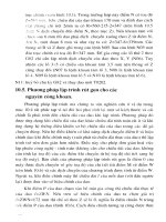
FIG.8-
OIFFERENTIAL
FOR ON-OFF
CONTROLLERS.
normal until the manual reset lever
or
button
Is
released.
This prevents the COfltrolier from resetting automatically,
even
if
the manual reset lever or button is
IiEld
down or held
in
by
tape, wire, or some other device. Manual reset
makes sure someone is
going
to
notice 6Ol1l8thing
is
wrong. A
good
servica lechnician will
correcllhe
prOOIAf11
before reselling the switch.
PROPORTIONING RANGE
Tha
proportiOning range (also
caliEld
Ihrottling range
usually
edends
above the set poim (Fig. 9). alihOugh
Qrl
some controllers it extends on
lxlth
sides
01
the set point.
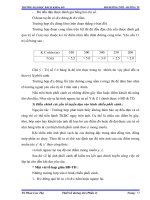
Pressure or temperature variations cause
the
bellows or
diaphragm to move,
caUSing
the potentiometer Wiper
(R
lerminall to move across its windings. This varies lhe
re-
sistanCe
between R
and
B,
and
Rand
W. The resu1ting cir-
cuit urtJalance drives a modulating motor or
mod:.JlalinQ
valve aCtuator and regulates the firing rale. (For a detailed
explanation
of
this operation, refer to
the
Flame Safeguard
Reference on Firing Rale Controls,
10rm
70-8117.) As the
controliEld variable rises, the
Wiper
will move toward the W
end
of lhe potentiometer, driving the motor or actuator to-
ward
its Closed position
ard
decraasing the firing rate. As
lhe controliEld variable talis,
lhe
wiper will move 'award the
B
end, driving the motor or actuator toward its open posi-
tion
and increasing the firing rate. Thus, a
CharlQ8
in the
controllEld variable wilt cause modulation
of
the firing rate
10
compensate for
fhe
Change and keep the pressure or
terrperalure nearly CQrlstanl.
t
,
-co
,,,.
B,, r->
IClO§W)
I
I
T
~"'OPOR
I (
POTENT'O"UER
T'ON'NG
Ii::,
"''''lOG'
(",~~;j]
: :
-NIGNFlIlE
10'ENI
5h
PO''''
+1'-Ol.L-~
L - +
•
J
&
ON
A'£>O
CtlfITROlU""
(:weH
""
THE
TN'
n"'ER",TURE
[Or<TAOl·
lEftSl.
THE
k~
PO,,"""
'IT
TNt.
Cl
TU
OF?tt:.
0""0
'
'
""'
E_
ill
SQ"f
C","'ROlLEIl'
(SUC"
"S
1HE
T1"0
TEM.E"
W"E
COHfIlOl·
LUI
VE
z
POTEHTlO"Uf'lll
OI"l:"''''T''''
IN
UN'IoO".
FIG.
9-
PROPORTIONING RANGE FOR
PROPORTIONING CONTROLLERS.
220
On
some controllers. the proportioning range is 1ixed,
while
on
others it is adjustable. On adjustable models, the
proportioning range scale is usually graduated
tram
A to F
.'!yith. a MIN (minimum) value below A.
The value
of
each
division depends
on
the cperaling
raf1Q8
and set
J,)Oint
at
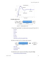
the controller. Proportionlng range charts like the one
shown in Fig.
10)
are available for different cperaling
ranges
to
determine the
pr~
seuing. (The propor·
tioningrange scales
of
some
t~ralure
controllers, like
the T991A
~d
B,
are marked directly in
degrees
For
q.
M'N'"
•
,
0
• •
\ \
,
"'OlO"?
&
rll.""RUU"l
'
•
1\
,
I'~
\
1\
1\
\.
1\
"
\
,
1\
1'-
,
".
•
,.
.
~
.
,
~
.
,
,
'''01'O''T10''''«;'
Cl alCRUS
F
& FOR
LOW
n"PlfLl,TURl
VAPOR_.RlUURl
SENS'''''
ELlMl
n
(T'"
COH?f'OLLl"'l
FIG.
10-
TYPICAL PROPORTIONING RANGE
CHART
FOR A
CONTROLLER'WITH
AN
AOJUSTABLE
PROPORTIONING
RANGE.
CHECKOUT
AND
MAINTENANCE
CHECKOUT
After the controller has been installed, wired, and set,
it
should be tested with the system
in
operation. First allow
the system to stabilize. Then observe the operation
of
the
controller while raising and lowering its set point. Pressure
or
temperature should increase when the set point
is
raised
and
decrease when the
SElt
point
is
lowered.
Use
accurate pressure
Of
tef'11)erature testing equipment
when checking out the controller.
Do
nOI
rely on inexpen·
sive gauges.
For an
on·off controller. make sure the swilch makes
and
breaks at the proper points.
Be
sure to consider the
differential. If the controller is
~£1ad
ol
operatinglffi-
properly, it may be further checked as lollows:
,.
Disconrlect the wires from the controller.
2.
Connect an ohmmeter between the switch terminals.
3. Raise the set
J,)Oint
of
the controller more than the dif-
ferential, The switch should either make
or
break,
depenc:J.
ing on the model
of
the controller.
(11
it
makes, the
If a
proportioning controller is suspected
of
operating
ohmmeler will read zero;
if
it
breaks, the ohmmeter will
imprope~ly,
it may be further cheCked
as
follows:
read infinity.)
1.
Disconnectlhe
wires
trom
the cOf1troller.
4.
Lower the set point
of
the controller more than the dif-
2.
Connect an Ohmmelel between cOf1trolier terminals
ferential. The switch shoold break
or
make, depending on
8 and W to measure the resistance
at
the potentiometer
in
its action in step
3.
the controller. The Ohmmeter should read about
135
Ohms
5.
An approximalion
of
the differential can be made by
or
270 ohms, depending on the model
01
the controller.
observing the change in set point r9QJired
10r
a resistance
3.
Conneclthe
ohmmeter between
cQnlroUer
terminals
change from zero to infinity.
Wand
R and raise the set point
of
the cOf1trolier above
fhe
For a
proportioning con/roller. make sure the modulat-
actual pressure
Of'
temperature being measured. The
ing
motor
or
modulating valve acluator reaches the low
ohmmeter should read the full value
of
the
J,)Otantiomeler
and
hiQh
fire
J,)Osilions
at the proper points.
If
the motor
or
measured in step 2
(135
or
270 ohms).
actuator runs in the proper direction when (he set point
is
4.
Slowly lower the set
J,)Oint
of
the controller while
00-
adjusted,
il
can be assumed that the controller
is
operating
serving the ohmmeter reading. The resistance should
properly. It it runs in the wrong direction, reverse the 8
a.nd
drq)
to zero at some sel point below the actual pressure or
W wires. Observe the action
of
the motor
or
aCluator tosee
temperature.
if
it stabilizes. If the motor
or
valve
is
moving cOf1stantly.
5.
An approximation at the proportioning
raf1lijJEl
can
bEl
widen the proportioning
raf1Q8
(if it is adjustable). a lillie at
made
by observing Ihe
chaf1Q8
In
set
J,)Oint
rElQUired
tor
a
a time,
unlil
the system
is
stable. resistance change from zero to full value.
221 71·97558-1
CALIBRATION
AU
controllers are carefully tested and calibl"aled at the
factory under controlled conditions. If the actual
~rating
preslil,lr.es_
or terrperatures
00
not malch
the
set
points,
most controllers can be recallbrated in the field.
FirSI
slsl
of
occasional inspection and blowing or brushing
away any accumulaled dirt and dust. To ensure
prq:er
functioning of lhe controller at all times,
an
~raUona!
check
of
the
Mtire
system Should be performecl
wring
routine maintenance checks.
check lhat the controller is level
(i1
it
hasa
mercuryswilCh).
Ralevel il if necessary, and recheck the
~raling
points. It
there
is
still a discrepancy:
1.
On
6Om8
controllers, the scaleplate can be moved
slightly
L;lP
oroowQ
u(\111
the sat point agrees with lhe actual
pressUre
0(
tef'rl)erature.
2.
On
other controllers, the set point Indicating dial can
be turnecl with a special calibration wrench until it agrees
wilh the actual pressure or terrperature.
MAI~TENANCE
The ,cover
of
the controller should be in place al all
times
to
protect the internal components tram din, dust,
and
~ysical
damage. ROUline maint9l'lBnce should con-
-,'
Occasionally, mishandling
of the controller may cause
a malfunction. A gradual change
Of
control point may
oc-
cur because
of
a very small leak In the lhermal system.
On
temperalure controllers, this
Is
mosllikely to be causadby
bending the capillary tubing too sharply, or too close to a
joint. Aging
althe
factory would have revealed the leak
if
it
had been presen1 at the lime of assembly.
If/he
tLbing
is
squeezed so hard or bent so Sharply that ils bore is com·
pletely closed
l,4), the controller will,
of
course,
be
ren-
dered entirely
in~ralive.
Deforming the bulb (or Olher
sensing element) will change
the
VOlume,
resulting in a
Shift in calibration.
Tnese
~
of
malfunctions should be
lool<ed
for ciJring maintenance. Controllers should
be
han-
dlecl carefully
althe
time
of
installation,
et.Jring
actual
use,
and
during mainlenance.
222
,
.~
PRESSURE
CONTROLLERS
A pressure controller
is
a device thai
monitors
the pres- waler heating systems, In gas
burner
systems,
and
in oil
sure
of
sleam,
air,
gases.
or
/iQ.lids.
AA
internal
diaphragm
burner systems. Honeywell pressure controllers available
or
bellows
responds
10
pressure
changes
and,
throu;j1
IS
for
use In these systems
wltJ
be
described In (he following
mechanical linkage, acluates a switch
or
polenllomeler
to
sections. Installation procedures
peculiar
to each system
keep the pressure within predetermined limits. Pressure
will also be
diSCUSSed.
controllers afe
com~nly
usaa'
on
steam boilers and hoi
PflESSUFi"E
CONTROLLERS
USED
ON
STEAM
BOILERS
AND
HOT
WATER
HEATING
SYSTEMS
The
pressure controllers discussed in this section can
be used with steam, air, noncombtJslib!e gases,
or
fluid
noncorrosive
10 the
pressure
sensing
element.
They
pro-
vi~
operating control
or
limll protection, depending
on
the
controller model al"d wiring hookup (Figs.
3-7/.
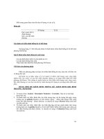
LOCATION AND MOUNTING
When used with sleam boilers, always
mount
the. con-
troller
above the
water
fine in the boilEir. A
steam
trap
must
always
be
connected between the controller and the boiler
(Fig.
11)
to prevent boiler scale and corrosive vapors from
atlacking the diaphragm or bellows.
The
1<::q:1
on
the steam
trap must always
be
perpendicular to
the
face
of
the con-
troller. 11lhe
f<::q:l is parallel to the contrOller, expansion
or
contraclion
01
the
1<::q:I
will tip the controlier
and
cause the
switch to operate inaccurately.
The controlier can
be
mounted
(1)
alongside the pres-
sure gauge,
(2)
in a
filling
on tile boiter provided
by
the
manufacturer,
or
(3)
at
a remote location in case
of
exces·
sive vibration. When making pipe conn&ctions, use
pipe
compound sparingly to seal tile joinlS. Excess pipe
c0m-
pound
may
clOQ
Ille
small hole in tile fitting al"d prevent the
controller 1rom operating properly.
~"E55U"E
,
,,,,~/~~O"TROLLER
.""~~
•
PIlESSOJII(.
Zkl
S7
10'A.
RIGHT
,
T
GAUGE
,
."2
TO~"2
(1
a
TO
aOj
WRONG
.&
l/O-'''C,"
BLACK
'RO"
~'~E
WI',"
,/
,a NPT
[XTER
l
T
f.
OS
Oil
BOTH
ENO~.
,
,e
BOILER
FIG.
11-
RIGHT
AND
WRONG
MOUNTING
OF A
STEAM
TRAP,
WITH
APPROXIMATE
DIMENSIONS
IN
INCHES
[MILLIMETRES
IN
BRACKETS].
NOTE: If using tile controller with a
CO!T'Pressor,
install a
dampening device
(wch
as
a needle valve. header,
or
surge lank) to dampen pulsations which can damage
the controller
or
reduce its life.
To
mounllhe
conlroller alongside the pressure gauge
(Fig.
11),
remove the gauge. In its place. install a steam
trap with a lee
on
tap. Using elbows
and
pipe nipples,
mount the controller
and
pressure gauge on the
ends
of
Ihe tee.
If it
is
not convenient
to
mount
lhe controlier alongside
the pressure
gauge, install a steam trap in the fitting pro-
vided
by
the boiler manufacturer. If there is no 1ilting.
mount the steam trap
al
a location recommended
by
the
boiler manufacturer.
Screw
Ihe
controller directly
to
Ine
steam trap.
If there
is
ex.cessive Vibration
at
the boiler that mayad-
versely affact the operation
of
the controller, the controller
should be mounted'
at a remote location. All piping from
the boiler must
'os
suitable and solidly mounted. The pip-
ing must
be
properlV pitChed to drain all cOndensation
back to the boiler. A steam trap
must
be
mountEKl
between
the remote piping and the controller.
HONEYWELL PRESSURE CONTROLLERS
AVAILABLE
FOR
USE
ON
STEAM BOILERS
AND HOT WATER
HEA,TING SYSTEMS
Honeywell pressU/8 controllers are
fistEKl
in Table
II
al
the el"d
01
this section.
along
with their applications,
switch types, al"d operating pressure ranges.
Fig.
12 shows the mcx:lels
IiSIEKl.
AlIl'T'\Ode1s
operate as
desCribed
in
Basic Principles
ot
Controllers except the
P455.
which is a corrtJination prq:;ortioning al"d on-otf
controller. lis operation is descri'osd next. For
furttel
infor-
mation, refer to
the
instruction sheers tor the controllers.
OPERATION OF THE
P455
COMBINATION
CONTROLLER
The P455 is a combination prq:;ortioning al"d
cn-otf
pressure controller. [n addition to a
prorortioning
potenti-
ometer, it
has
an
spst swilCh with a subHacUve ditferenlial
that breaks
on
pressure rise.
Tha
main scale is set at the
manmum
pressure
desirEKl.
The differential
is
adjustEKl
in-
stead
of
the
prcportioning range. Tl"le proportioning tange
will automatically
be
sat
10
approximately 85Percent
of
the
differenlial. (The differential sca[ap1ale
is
graduated from
A to F with a MIN value below A. Refer to the P455 instruc-
tion sheet for values
01
the
differential
and
proportioning
range.)
223
71-97558-'
FIG.
12-
HONEYWEll
PRESSURE CONTROLLERS
AVAILABLE
FOR USE
ON
STEAM
BOILERS
MID
HOT
WATER
HEATING
SYSTEMS.
'.'
The
P455
also has a UNISON/SEQUENCE adjust-
ment, which provides a choice
01
firing rale
at
burner
startl.P. The odjusling dial is located just
below
the wiper
armof
the
potentiometer
(Fig. 2?).
The
dial
is
turned
so
Ihe
arrow is at
Ufor
unison
q:)(lralibn, at S for sequence cpera·
lion,
or at
one
of
3
inlermediale
positions,
Fig. 13 sh(w,rs
the operation
at
Ihe P455
for
each
of
these p::lSitions.
In
(he
UNISON position,
Ihe
prcportioning
range
is:
en-
tirely
within
Ihe
differential range,
so
the
on-ott
swi'ch and
the prClJX)rtloning potentiometer are functioning
at
the
same Ifme. When
Ihe
pressure falls
to
the sel point minus
the differential,
Ihe
on-oN
switch
makes
and
the burner Is
lumacl on. The potentiometer
wiper
is
aU
the way over to
the
Bend,
lhe
firing rate Controls are
a!
the high fire jXlSi-
tion.
and
the bUrner starts
al
high fire, As the burner heats
l4=l
and
the pressure increases, the wiper moves toward
the W
end
of
the potentiometer. It the pressure contlnues
10
Increase, the Wiper moves all the way to the
Wend
and
!he firing rate
conlrols
are
at
the
low
tire
~ilion.
Ordinar-
Ily, modulallon keeps the pressure
belW9Eln
thess
posi-
lions within
lhe
proportioning
range. If
It
prOblem devek:ps
or
the Iced drops suddenly,
and
the pressure continues
10
rise, the
on~f'I'
switch
breaks
and
shuts down
lhe
bUrner
when the pressure reaches lhe
main
scale sel point.
In the
SEQUENCE
posilion,
Ihe
prqx>rtionlng
range
is
entirely below
Ihe
differenlial range, so the
on~ff
switch
and the proportioning
potentiomeler
are
not
funclioning al
224
the same time. As in the UNISON position, when the pres-
sure falls
10
lhe sel point minus
Ihe
differential,
Ihe
on-off
switch makes
and
the burner is turned on. However, the
potentiometer wiper is all the way over to the
Wend,
the
1iring rale controls are
al
the
low
tire position,
and
the
burner starts at low fire, It the pressure continues to fall
be-
10re
the burner can heat up, the Wiper moves toward the B
end
at
the poten/iometer. If the pressure 1alls far enough,
Ihe wiper moves all the way
10
the B
end
and
the firing rate
controls
at
the l1igh fire posilion. As the burner heats l.4)
and
the pressure increases, the Wiper moves toward the
Wend
at
the potentiomete(. Again, the pressure
is
ordinar-
ily kept within the
proportioning
range. t1the pressure con-
linues to rise, the wiper moves all the way
10
theW
end
and
lhe
1iring rale contrOlS are at the
low
tire
jXlSilian. The
burner slays at low 1ire as the pressure increases through
the differential range,
and
is Shut do
·:n when
Ihe
pressure
react'19S
the main scale sel point.
In an intermecliale jXlSition, the
proportioning
potenti-
ometer is
functioning
partly
wllhin
the differential range
of
the
an~N
switch-the
amount varies with the
~ilion.
This
provides a
ChOice
of
lhe
firing
rale-somewhere
be-
tween low
1ire
and
high
fire-al
burner startl4=l when the
on~ff
switch makes. As shown In Fig. 13, the pressure
range over which the burner will operate at low fjre also
varies with the position 011he UNISON/SEQUENCE dial.
•
(
-"'GH
•
,,~t
,
,.
I
"'I.UNG
""ESSURE
"
",
j
U"'SON
/
OI'ERATlO,",
r-_~/
\
\,
\ I
~
\ /
~
\
I ( /,,"
\"'li' 'oJ
_
l~"
I
-"'G
a
"M
I
I
-H'OH
•
FIRE
I I
I
I
I •
',AE
I
r
iL"
I
I
I
I
I
I I
I
'HTrRWW'''rf
OHRATlO'l
\
-,
I
I
rli
l
1'-_
/
-,
\
,\J
I
\
//\,
\_~
I I
I",
1\.\1
r-
,
\"""(\1
I
I 1
-
\ I
I I
1'':-:,
r\il
J I
\"5\
''''
.
./
I
\-\
''''
I I
1
<;
,,_
I
L
____
J
L
__
:'_J
L
____
J
\
",.,loC>NlllOJ<JVICE
AOJusr
nn
I
I
I
U(]UENn
O"ERA"<lN
, \ I
l@)
.I
FIG.
13-0PERATION
OF
THE P455 COMBINATION PROPORTIONING
AND
ON-OFF PRESSURE
CONTROLLER.
PRESSURE
CONTROLLERS
(PRESSURE
SWITCHES)
USED
IN
GAS
BURNER
SYSTEMS
The
pressure controllers used
in
gas
burner systems
are
commonly
called
gas
pressure swilchas_ They may
be
used
with natural gas, LP gas, or air.
(The
C64sC
and
D
models
can
be
used only with air.} They provide safety
shutoff
or
diflerential-pressure control, depending on the
controllsr model and wiring hookup (Figs. 3-5). No propor-
tioning controllers are available tor use in gas burner
systems.
LOCATION
AND
MOUNTING
Gas pressure switches in the main burner line should
be
located downstream from the PRII (pressure rBgJlaling
valve).
The
low gas pressure switch should
be
localed
u(r
stream from the safety shutoff valve(s). In a downstream
location, there
would
be
zero preSsure when lhe burner
Isn'( running
and
the safely shutoff valve(s) is closed. This
could
prevent startup
or
reqUire manual reset every time
the burner
is
started. The high
gas
pressure switch should
225
be
located as near
thE!
burner as
p:;lSSibre.
Typical
loCa-
tions
arE!
shown In Fig. 14.
A pressure switch is
t JSllally
rrounted
dlrectPy
on the
main pipe
by
Inserling a
tBEI
in the
pipe
lJne,
and connect-
ing a pipe nil=flle
at
appropriate size
10
the
tBEI
(Fig. 15).
Screw the main pressure connection
ot Ihe pressure
switch to the
pipe
nil=flle. The main connection
is
a
heJt-
agonallilling
with 1/4
or
1/2
inch NPT Internal threadS.
To
avoid leaks and damage to the
case.
use
a parallel jaw
wrench
on
the hexag::mal fitling close 10 lhe pipe
ni~le.
Make all connections carefully and lest lor leakage. Do
not
tighten
rhe
pressure
swifch
by
hand
by
holding the case.
In some cases, it
may
be
more
convenient
(0
mountlha
pressure switch
on
a nearby wall. using the optia'lal
mounting bracket. The braCket should
be
Installed before
connecting the
piping
from the
main
line.
ContrOllers with mercury swilches (C437. C447,
C637,
(;647) must
be
carefully leveled
as
described In Basic Pri".
71-97558-1
FIRING
RATE
SSOV
CONTROL
o MSOV MAIPIl
VENT
'RV
MSOV
i=t~~;E}::;~BUlrER
HIGH
GASPS
BURNER
PRESSURE
• PILOT
LINE
TEST TAP
MSOY
_
MANUAL
SHUTOFF
VALVE
PRY -
PRESSURE
REGULATING
VALVE
PS
- PRESSURE SWITCH
SSOY
- SAFETY SHUTOFF
VALVE
FIG.
14-TVPICAL
LOCATIONS
OF
THE GAS PRESSURE SWITCHES IN THE
MAIN
BURNER
LINE.
ciples of Controllers. C645 Pressure Swilches are snap-
a.
Hazardous (combustible)
gas-Install
a vent pipe at
acting,
so
they 00 nol have
10
be
leveled, The C645A,B, or the venl conneclion
so
that any gas leakage will
be
o
may
be
mounted in any position, but they are slighlly vented into the combustion Chamber or to another
more accurale when mounled with the diaphragm
hOri·
safe place in case the diaphragm in the pressure
zontal. The C645C (low operating pressure range) must switch fails,
be
mounted with the diaphragm vertical and
(he
vent con- b. DifferentjaJ
pressure-Connect
the high pressure
nection (bleed fitllngl at the I:ollom. side
at
the system
to
the main pressure connection,
A
vent connection
(1/B
inch NPT with inlernal
lhreaci5)
and the low side to the venl conneclion. This appli-
is provided
on
all pressure switches. This connection must
Cation
cannot be used with hazaroous gases as no
be
used
in the following
awlications:
venting
is
possible.
c.
Negative
prflSSUre
- Connect the low pressure side
__
~AS
~~tsSV~E:
SWITCH
IAT
RIGHT
.~GLE:S
TO
THE:
M.'~
~I'E:
L'~E)
Ii
MAI~
~IPE
L1NE
",'EHE
[TIJR~
TO
LEVEL
T"E
~RESSURE
SWITCHl
FIG.
15-
MOUNTING A
GAS
PRESSURE
SWITCH
DIRECTLY
ON
THE
MAIN
PIPE.
to the vent connection. This
awlication
also
cannot
be
used with hazarcbus gases,
When using a pressure switch with a low pressure
range, momentary pressure surges
or
&bumps" can
cause the switch to break. Orifices are available for C437
and C637 Pressure Switches
to
eliminate or reduce chal·
lering or nuisance lockouts caused
by Ihese
-bumps.·
An
orifice is inserted in the main pressure connection (Fig.
16)
[0 reduce the effect
at
pressure surges. The bushing and
ORI FICE TOOl
AG.
16-INSTALLING
AN ORIFICE IN A C437
OR
C637.
226
onfice
1001
shown
are used only
for
installation at the ori-
tice, and are removed afterward.
PRESSURE SWITCH
SETIING
Industrial Risk Insurers (formerly F.LA.)
recommenc1s
that gas pressure switches
on
the manifold
be
seln
accor-
dance
with the turncklwn range
of
Ihe installation. They
recommend
thatlhe
high gas pressure switch be sal
20
per,cent above Ihe maXimum firino rate pressure, and
the
low
gas pressure switch
be
set
20
10
50
percent below the
minimum
firing'
rate pressure, wilh the preference being
20 percent.
,,'
J.IMllli, C0l'ltrp1lehf
",
'andlntlllrlocks
HONEYWELL
PRESSURE CONTROLLERS
AVAILABLE
FOR USE IN GAS BURNER
SYSTEMS
HoneyweJl pressure conlrollers evailable are listed
;n
Table
II
al the end of Ihis section, along with their
awlica-
tions, switch types, and operating pressure ranges. Fig.
17
shows the models listed, All models operale as
d&-
scribed in Basic Principles
01
Controllers. For runher infor-
mation, reler to the instruction sheats for the controllers.
PRESSURE
CONTROLLERS
USED
IN
OIL
BURNER
SySTEMS
Prassure controllers are used in oil
burner
systems to
supervise oil pressure and to supervise the pressure
01
the
atomizing medium (if used).
OIL
PRESSURE SUPERVISION
The
Oil
pressure controllers (also called oil pressure
SWitches) discussed in this section can be used with
any
type
of
fuel oil, inclUding heavy preheated oils. They have
a stainless steel diaphragm to resisl corrosion. The dia·
phragm transmits changes
in
oil pressure
to
an spst mer-
cury switch Ihrough
a mechanical linkage.
The
L404T
and
Ware
high pressure limits; they break a
circuit and
st'1ut
down
the system
if
the oil pressure gets
too high.
The L404V and
Yare
operating controllers
and
low
pressure limits: they
preventlhe
system from staning
untillhe
oil pressure is high enough, and they
Shut
down
Ihe system ir lhe oil pressure falls too low. TIle
L404T and
V have adjustable subtractive differenhals: the L404W
and
Yare
manual reset models.
C447.C547
_
LOCATION AND MOUNTING
Oil pressure controllers can
be
mounledat
any location
in
Ihe ojl supply line, dePending
on
Ihe application. Typical
loca/lons are shown in Fig.
18. The low oil pressure switch
should
be
located upsrrfjam from
1M
safely shutoff
valve{S),
In
a downstream location, there would
be
zero
pressure when the burner isn't running and
the
safety
Shu10ff
valve(s)
is
closed. This could prevent startup
or
re-
quire manual reset every time the burner is staned. The
hiGh
oil pressure switCh should
be
located as near the
burner as possible.
An oil pressure controller is mounted directly
on
the
main pipe
by
inserting a tee in tha
pipe
line. and
cOnnect-
ing a pipe
,iJ:Ple
of
appropriate size to lhe tea
(FiQ.
19).
Screw Ihe he:tagonal fitting (1/4 inch NPT with internal
threads)
at
the pressure controller to lhe pipe
niJ:Ple.
To
avoid leaks and damage to
Ihe
case,
use
a paralle! jaw
wrench
on
the hexagonal
filling
close to the pipe
niJ:Ple.
Do
not
tighten
rhe
pressure contro/ler
by
hand
by
holding
the caSe.
FIG.
17-HONEYWEU
PRESSURE SWITCHES AVAILABLE FOR USE
IN
GAS BURNER SYSTEMS.
227
71·97558-1
MAIN
mL
UNE
•
TO
OIL
)=~~=~==p':I:;!==~=:::t';j.E:J==-::=CJ-=t~:E~BU;NER
FIRING
SSOV
ANO
RATE
RECIRCULATING
CONTROL
VALVE
LOW
A.M.PS
ATOMIZING
MEDIUM.
====:":===::=J
(AIR
OR
STEAMI
"
MSOV
- MANUAL SHUTOFF
VALVE
-
PRESSURE
SWITCH
ssov
- SAFETY SHUTOFF
VALVE
A,M,
PS
- ATOMI21NG MEOIUM
PRESSURE
SWITCH
FIG.
1B-TYPICAL
LOCATIONS
QFPRESSURE CONTROLLERS (SWITCHES)
IN
AN OIL BURNER SYSTEM.
Make all pipe
conneclions
in
accordance wilh
ap-
proved 5tandardi. Use only a small amount
of
pipe com-
pourd
10
seal the connection joints. Excess pipe
Corrp:lUnd may Clog
Ihe
small hole in the
filling
and pre-
vent the controller from operating prcperly.
When
used with preheated oil, a siphon
10ClP
must al-
ways be connecteCl between the controller and the main
pipe {Fig.
20)
to provide thermal buffering.
The
10ClP
must
always be perpendicular
to
the face
of
the controller. If the
10ClP
is parallel
10
the controller, expansion
or
contraction
of
the
10ClP
will
tip
the controller
and
cause the switch to
cperate lnaceuralely.
Oil pressure controllers have· mercury switches, so
they
must
be
leveled
for
proper operation.
If
mounting di-
rectly
on
the main pipe (Fig. 19), install the controller
at
rIght angles to the pipe; leveling can then be accom-
plished
by turning the
pipe
100.
If
using a siphon
10ClP
with
prehealed oil (Ag. 20), leveling can
be
accorTfJIlshed
b)I
carefully bending
the
siphon
10ClP.
The controller is level
when the leveling
indicator
hangs
freely with lis pointer di-
rectly over
the Index
mark
on
the back
of
the case
(see
Rg.2).
WIRING HOOKUPS
If the oil burner system is a single burner system with an
integral oil
pump,
connectlhe
oil pressure controller In
se-
ries between the flame safeguard control and the main oil
valve solenoid (Fig. 21).
If
it is a single burner
or
a multibur-
ner system with an external oil pump, connect the oil pres-
228
sure conlroller in series wilh the other controllers, limits
ard
interlocks (Fig. 22).
SUPERVISION
OF
ATOMIZING
MEDIUM
PRESSURE
(AIR
OR
STEAM)
When air
or
steam is used as an
atomi.ing
medium,
aulhorities having jurisdictiqn (approval bodies and
codes) often require
a-rowiimitto
prevent openinQ
of
the
main oil valve unlil sufficient atomizing pressure
is
pre-
senl,
and
to shut Gbwn the system if the atomi2inQ pres-
sura falls
too
low.
The L404B Pressure Controller, designed
tor use
on
steam boilers
and
hot water healing systems, is recom-
mended
tor
(his appllcallt:rl.
It
has an spst mercury switch
wilh
an
adjuslable
Slblraclive
diMerenlial. The switch
makes a circuit when the pressure rises to the set jX)int,
and
breaks when the pressore fcllls to the set point minus
the differential (see Fig.
8).
The L404B is available in 4
0p-
erating pressure ranges, from 2 to 300 psi.
LOCATION
AND
MOUNTING
The L404B is
mounled
in
Ihe
supply line for the atomiz-
ing medium (Fig. 18). Follow the same
mounting
instruc-
lions as for the ofl pressure c?1trollers.
WIRING HOOKUPS
The cperation
of
the L404B Is the same as for the
L4D4V,Y (makeS
on
pressure rise to setjX)int).
II
should
be
connected In series with lhe oil pressure controller (Fig.
21
or
22).
,
/Oll
PJtU,5UR£
~ONTFlQLlE~
.,
(Ar
"'G"r
ANGLES
TO
THE
"'
".E
UNE)
.'.fTEE
(lU""
TO
U\I[L
THE
CONrJtOLUlOI
L
""
FIG.
19-
MOUNTING
AN OIL PRESSURE
CONTROLLER DIRECTLY ON THE
MAIN
PIPE.
,
;
4
2
T051
1114 TO 1401
L
14026
SIPHO"&
LOOP
•
Oil
PIlUSWI[
CONHIOllER
•
PflEI'iE",Tl:O
OIL
PREl'itATED
O'L
SUP'PLV
LINt
SU","L.II 1,.10'[
&
(,
eli
eLACI(
IRON
"P[
WITH
1/""'"PT
[)(TEIlN
1
THREAOS
Oil
BOTH ENDS.
8tHD
TIiE
SIPHON
LOOP
TO
LEVEL THECONTIIOLL.ER.
I
"F'"
GC" =2-=O-_-C
R
:cC"O:cC"WC"R"O"NC"G= =M"O"U-
N
='::N"G-O"F"A"
"'-=GC"H::T"
AH
-C
T
SIPHON
LOOP,
WITH
APPROXIMATE
DIMENSIONS
IN
INCHES
[MILLIMETRES
IN BRACKETS).
HONEYWELL
PRESSURE CONTROLLERS
AVAILABLE FOR USE
IN
Oil
BURNER
SYSTEMS
Honeywell pressure controllers allailable are lislad
In
Tabla
II
al (he end or this section, along with their
awica·
!.ions,
switch types, and operating pressure ranges. Fig.
23
shows the models listed. For further infonna(ion, refer
to the instruction sheets
lor
lhe con/rollers.
OllPAE$SIJAE
,
.,"vALvE
'~""l
UoHGUAIIIO
CONTIIIO~
U
~
-
FIG.
21
-
HOOKUP
OF AN OIL PRESSURE
CONTROLLER USED
ON
A
SINGLE BURNER
SYSTEM
WITH
AN
INTEGRAL
OIL
PUMP.
FIG.
22-
HOOKUP
OF AN
Oil
PRESSURE
CONTROLLER USED ON A SINGLE
BURNER OR MUL
TIBURNER
SYSTEM
WITH
AN
EXTERNAL OIL
PUMP.
L.O&Oo&T,V,W,Y
L
__
('_·_'_·B_"_'_'._'_'_A_._'
~
FIG.
23-
HONEYWELL
PRESSURE CONTROLLERS
AVAILABLE
FOR USE IN OIL BURNER
SYSTEMS.
SETTING
PRESSURE
CONTROLLERS
The operating p:>ints
01
pressure controllers are set
by
tq::l
of
the case.
as
shown
in
Figs.
24
and 25. Sealeplales
turning ild}usting screws or knobs, usually located
on
the
are
rnar1<oo
in in.
we
(inches
of
vwater
colLKm),
in
psi
229
71-97556-1
I
(pounds per SQJareinch),
or
In oz./in.
t
(ClUl'lCeS
per
S(JJare
inch; 1
oz./ln.'
= 0.0625
ps~.
Those which extend into a
vacuum range
(prescurK
below
atmospheric pressure.
Which
15-0
pslg
or
~rQ){imalely
14.7 psial
are
mar1<:ed
in
In.
Hg
(inches
of
mercury; , In. Hg
""
0.4912 psi). Many
scaleplales are also marked in metric equivalents,
such
as
mm
,we
(milllmelres of water column), mbar (millibars),
kll1
cmr
(kilograms
per
squate
centimetre).
or
kPa (kilopas-
caIS).
SOme
international models
are
marked in
kll1CfT11
and
kpa.
Table I lists conversions
befween
II18se units.
SETIING
ON-OFF PRESSURE CONTROLLERS
The
main
scale is
SEll
at the desired
~raling
pressure
by
turning the main
SCale
adjus\irQ
screw
(Fig.
24)
or
Inter·
081
dial (0447,
C647J
unlJl the main scale
selling
indicator
is
al.
thedBslred value. On
some
models,
the
differential is
fiXed;
bJt
on
ITOSt
I'TlOd9ls.
it is adjustable
by
turning
lhe
differential adjusting screw (Fig.
24)
or
internal dial
(PA4Q4)
until
the
differential
tatting
indicator Is at the de.
sired
~akJe
Manual reset models
are
reset
by
pushing
in
and
releasing
1he
manual reset lever (Fig.
24).
SETIING
PROPORTIONING PRESSURE
CONTROLLERS
The
main scale Is
set
allhe
desired q?eraling pressure
by
luming
the
main scale adjusting sere
(Fig. 25)
unlillhe
main
scale se1ting indicator is at the
minimum
pressure
desired (excepl the P455, which 'was d8scribed
~revi.
ouslyl. TIle .oroportioning ranoe (also called throWing
range) e.:tends above this value,
as shown in Fig. 9.
The proportioning range may
be
fixed
or
adjustable,
depending
on :he controller model.
An
adjustable model is
sel
OJ
turning the
proportioning
range adjusling screw
(Fig.
25)
untillheproponioning
rangesel!ingindicalor
is af
the dasired
val~.
"Fha
prop::>r1iQlling range scale
is
gradu-
TABLE
J-PRESSURE
CONVERSION TABLE
INCHES
mm
mllll-
,p,
kg/em
2
0'
0'
p"
brr.
b
WATER
WATER
a
,
0,249
3
0.036 25.4 .49 0.00254
7.47
0,00762 0,747
0108
75.2
,
, .245
10
12.45
0,0127
0,181
127
24.91 0.0254 2.491
0.0533
0.361
254
S.231
0.75
533
.31
2'
68.95 0.0703 6,895
1.000 703
,
7 ,
-R~
7
0.7031
2768
10
689.5 68.95
703'
,
105~6
1.055
415,2
1C.34
553.6
20
"
14062 1379 1.406 137.9
-
2t13
2.461
24608
24'.3
,38<
96eB 35
35154
3m
3.515 344.7
7,031
SO
689.5
4152 _
70309
689'
2'68
'00
10.55
105463 10342
'SO
"",
210927 21.09
2068
8304
JOO
""54
5536
2
1406
137, 0.1406 13.79
,
.4
,
3516
3447
0
51'
34.47
a,rT'ITI
of
waler =
OOOC1
kg/em'
b,
millibar
~
J,1
kPa
c1
kg/Cm~
= 98.0065 kPa
FIG.
24-
SETIING
A
TYPICAL
ON-OFF
PRESSURE
CONTROLLER.
ated from A
to
F
with
a MIN (minimum) velue below
A.
TIle
value
at
each
division depends on
lhe
pressure range
of
the controller. (Refer
to
the instruction sheet
for
the con-
troller
10
deleJ:nine the value.)
-
"'
IN
.,
$C"'LCP~A
TE
1
'"
8
.,
~
'ih
lOA
IN
SC
lE
'Ii
;H
SETTING
><.
1;~
INO'(ATO~
.:
M"r"
SCAlE
AOJUST'NO
SCREW
PROPORTIONrNG
R"'N(;E
ADJUSTING
seRE'"
PROPORTIONING
R
NGE
StTT'NG
INOICATOP
WIPER
AR"'ISI
FROPORT'ONIN(;
RANGE
SC
LHLATE
'"
FIG.
25-SETIING
A
TYPICAL
PROPORTIONING
PRESSURE
CONTROLLER.
2]0
TABLE
II-SUMMARY
OF
HONEYWELL PRESSURE CONTROLLERS
SySTEM APPLICATIONS
TYPE
PRESSURE
RANGES
MODELS
SWITCHING
ACTION
PRESSURE RANGES
AVAILABLE
NO.
LOWEST
HIGHEST
.
,
St.om
Boilers
,,'
Hot Water
Heatinl;l
9,'stems
OperaUng
Coo,,",
'"
limit
Protection
On-Ofl
Cootrollerf
limit
High
Law
(Vapor
Heating
Systems)
Vacuuml
Prl$Swe
l404
U,,,,
PA404A High
LSnit
PA404B
Fan
Control
L4079 (High
Limits only)
l408
l508
l411
1 spst
mercury a
1 spdt
mercury
1 spst
snap-acting
1
Of
2 lfpat
!tllap-acling
1 spst
mercury
1 spdl
mercury
1 spst
-"'"
,
,
2
2
2
1
0\:1 15
psi
2 \:115
psi
0.5 \:I 9
pSI.
2 \:I 15
psi
o
to
'8
ozlsq in
(0
to
,
p!t~
22 ill.
Hgl:!
vacuum b
35
psi
pressure
20
•
:lOO
,.1
20.
:lOO
,.
31015
,.
10 b
150
,,,
0.'
psi
~.
Operating Control
(Regulate Firing
Rate
or
Prenura)
Proportioning
Controller<!
Highll.o
/
Vacuum
191
P4SS
d
potentiomemr
spst and
POterrtiometerd
7
3
22 ill. Hgb
vacuum
to
35
psi
pressure
o b
15
psi
10 \:I
300
'"
10 \:I
300
,'I
Goo
Burner
Systems
safety
Shutoff
safety
Shutlrt
OfAJr1Iow
Switch
Gu
Prassure
Switch
Gas/Air
Pressure
Swi10h
High
Law
Law
0447
0647
C4J7
0637
C645A. B
C645C.O
(Air
only)
1 spst
mercury
1 spdt
mercUl)'
1or2spm
mercury
1 spdt
mercury
1 spst
snap-acting
1 spdt
snap-acting
2
,
2
2
'.30
psi
1/2
to
5-112
in.
wee
3
b21
in.
wee
0.6
to
5.3
In. wee
10
\:I
100
psi
1 \:I
10
"
,."
in.
wee
3 \:I
21
In.
wee
Oil
Burner
9,'stems
High
limit
low
Limit and
Operating Control
lDwlimitlof
Atanizing
Medium Pressure
Oil
Preseure
Co",,,,
,
On·Ort
limit
(Air
Of
Sloom)
-
-
l404T. W
l404V, Y
l4048
1 _pst
"'""''''''
1 spst
-"~
2
,
10
\:I 50
,.
2 \:I 15
psi
25
to
150
pO
20.
:lOO
"
8 Except the
l404F
hich has
an
spdt MICRO
S'oVITCH
snap·acting switl:h, and the
L404l,
whiCh
h&lI2
spst men::ury
SYfiIl:has.
brnchaa
at
mercury; 1 in.
Hg
=
0-'912
psi
""
3.387
)(Pa.
c Bellows-operated potentiometer: the L910
Iw.II
2 b allow control
at
211"1Ot:lr8
in
unison.
dThe
P455A
is
a combination proportioning
and
on-otr controller. It has an spst
5l1ap·acting
switl:;h ftlr on-otr control,
and
a
135
otm potentiometer ftlr proportionirJ9 control
e Inches
at
water column; 1
in.
we
0.036 psi = 0.249
koPEI.
231
TEMPERATURE
CONTROLLERS
A temperature contrOller is 8 device which acts indi-
rectly
10
regulate
the temperature
01
air or liquids. A
sens-
ing
elame"U responds
10
temperature changes and.
1hrOl./ttl a
diaphragm
or
bellows
and mechanical linkage,
actuates a
switch
or
potentiometer
10
keep the lempera-
ture within predetermined limits.
Temperature controllers
we
commonly used
In
flame
safeguard systems
to
reQJlale
the
temperature
011iquids
in
toilers
()(
lOtorage
tanks, and
for
fuel chanceoV9I
(switching from
crle
luello
another when the temperature
rises or
falls).
TEMPERATURE
SENSING
ELEMENTS:
The
temperalure conlrolJels
used
In flame sakQ;a{d
applicatiOl'l$
hSWil
silMr
vapor-pressure
or
liquid-filled
aenslng
elemenls
Various
types of these
elements
are
s.rnmarized
in
Table
11/
at
the
end
of lhis discussion.
,
VAPOR·PRESSURE ELEMENTS
A vapor-pressure temperature sensing
element
c0n-
sists
01
a remote
bulb
connected \0 a
~
in
the
c0n-
troller
by
a
~jl1alY
tubing. These
meta!
~ts
contain a volatile
liquid
and
the
vapor
from
it
When a volatile IQJId is
c.Ql1fiQed,
a portion
of
the
liQ.Jid
is
~.iven
offas a
vapor
(jusl as steam is driven
off
by
boiling
wale~
until a limiling pressure is developed. This pressure
Is adirect function
of
the
t~rature
of
the
liQ.Jld,
particu-
larly af thElliqJid SUrface
(the dividing lina between the liq-
uid and the VajXlrj. Changes
of
temperature thus result
in
corresponding changes
ot
pressure. This relationship
is
shown
in
Fig.
26.
T[""l:R~TURE
FIG.
26-TEMPERATURE-PRESSUAE
RELATION-
SHIP IN A
TYPICAL
VAPOR-PRESSURE
TEMPERATURE
SENSING
ELEMENT,
The
vapor pressure increas9S
wilh
'BI1l'9!alure,
as
shown
by
the curve
in
Fig. 26, until the fadeout tempera,
ture
Is reached.
This
is the temperature
al
which
all the
liQ-
uid has Vl'tpOrized
so
lllere is
no
liQUid
letl in tile s','Slem. A
further rise in temperature prOduces a more gradual rise
in
pressure conforming to the gas laws.
The
contro'ler must
be
desi"n91::fscdhe
1adEloul
temperature will
be
higher
lhan the maximum operating temperature.
For reliable operation, the
liquid
surface
mLJ!;I
always
be within the bulb.
As
long as
the
liQ.Jid
surface occurs in
the bulb, the bellows and capillary may be filled with either
liq.JJd
or
vapor
wllhout
aNecling the control
0'
lerrperature
al the bulb.
Qlangas
in bellows
or
capillary temperature
will only cause condensalion
or
evajXlratlon
Of
a lillie iiquid
in the bulb, with a
~ligi!;!'e
change
Of
pressure in the
system.
Vapor-pressure lemperature sensing elemems have a
very
smalltime
lag, and temperature variations along the
capillary
and
bellows (within the r9Slrlclions
for
Jow
and
high
t~ratul'8
elemenls, which will
be
described
late~
cb
not affect the plecise control
01
the
remote bulb
eleme"t
There are 3 types
or
remote bulb vajXlr-pressure
ele-
ments,
~ng
on
the bulb-to-bellows
tel'Tl;:JElrature
re-
lalionship. They differ
in
lhe
size
of
the bultJ and in
thai
relative amounl
01
liquid contained in the bulb and in the
bellows.
LOW TEMPERATURE ELEMENT (FIG. 27)
A
low
l~alure
e/el"l'l6l1t
/also called a
"/imiled
fill"
or
"ladeout~
element! is designed to operate with the bu'b
always
colder than the bellows and capillary. The system
contains a limited amounl
of
liquid
so
lhat
fa,jeoul will
0:'
cur
al
a temperature not much higher than the
maximu'T1
operating tefTl)erature. Therefore the bellows and capil-
lary are always filled with vapor.
As
the lemperature
attha
bulb rises, a little more vapor will
be
prOduced in the
bUltJ,
increasing the
p'essure
at the bellows.
As
lhe
tefTl)eratu~e
falls, a litlle more
liQ.Jid
will condense in the
bulb
and the
pressure will decrease.
,,~
LWAYl
COLDER
Ir
__
",.AH
'~LLOW<
L'QU'D
FIG.
27-
DIAGRAM
OF
A
lOW
TEMPERATURE
VAPOR-PRESSURE
TEMPERATURE
SENSING
ELEMENT,
Condensalion occurs first al the
COldest
paint
in
the
system. Therefore, the bulb must always
be
colder
t1-an
lhe bellows and capiUal'\'.
If
lhe lemperalure
at
any
~inl
alone the capillary or
al
the bellows falls below the lem-
232
perature at the bulb, the
liQUid
surface will shift to the cold
spot
outside the
bulb
and
Il'1e
bulb will lose control.
As
not
much
liQUid is required, (he
bulb
is
small-1/2
loC:h112.7 milllmetres,
or
mm] diameter by 4 inches
[102
mmllong
is
a
common
size. The elevation
01
the
bulb
with
rasped
10
lhe
bellows
is
not
critical; the prassure head (j&.
veloped by the weight
01
Il'1e
vapor in the capillary
and
bel-
lOWS
Is negligible.
Typl~le
ranges
tor
low
temperature elements are
minus
130 F
10
minus
70 F [minus
90
C
(0
minus
57
q at
one
eJ(lreme~ar1d
plus
65 F
10
plus 95 F [plus 18.5
Ctoplus
35-C]
al
the'other.'Themaximumsafe temperature,l.e., the
bulb temperature at which
lhe
maximum safe bellows
pressure is reached,
is
generally much higher than the
op-
erallng
range
of
lhe
controller. This is beCause fadeout oc-
curs
Just
above
Ihe
maximum
operallng temperature, so
llote
pressure increases
much
more slowly at higher tem-
~~~'LJ!QS
(see the gas curve
in
Fig.
25).
HIGH
TEMPERATURE
ELEMENT
(FIG.
28)
A
high
temperature element is desigIed
to
q:.erate with
lhe
bulb
always warmer than the bellows
and
capillary.
This system contains enough liquid
so that, at the highest
operating temperature, the bellows
and
capillary will al-
ways be
tWed
with
liquid
and
the bulb wlll contain some liq-
uid.
As the temperature at the bulb rises, more vapor will
be
produced
In the bulb, il]creasing the pressure on the
liqUid surface
and
also at the bellows.
As
the temperature
As
the bulb must cOnlaln only enough liquid to ensure
that there will
be
a small vapor space present at the lowest
operating temperature
and
a little liqJid present
at
the
hil1'esl
q:.erating temperature, the
bulb
Is
small-1f2
inch
(12.7 mm] diameter
by
4 Inches j1021TVTl]long is a
com-
mon
size. Preferably, the
bulb
shOlJId
be at about the
same
elevaliooasthe
bellows.
It
there
is
a large difference
in elevation, the pressure
head
developed by the weight
01
;/?::::t-l,.Imlts><C·oot,ollers
:;{;:'::K,:<:::'~ij#'~llh't'~'r1(,)Cks
the liquid In the capillary
and
bellows
would be ad:Iad \0
or
subtracted
tram
the vapor pressure
and
might cause
Im-
prc:per calibration
at
the controller,
Typical extreme scale ranges
tor
high temperature
ala-
menls are
plus
75 F
10
200 F [plus 24 C to 93
CJ
and
plus
510 F to 700 F [plus 266 C to 371 C]. The maximum safe
bulb temperature, Which at
high
temperatures also in·
cludes the safe temperature
of
the metal
or
the melling
point
of
the solder, Is generally
not
much
higher than the
top
of
the c:perating range
ot
the contrOller.
CROSS-AMBIENT
ELEMENT
(FIG.
29)
A cross-ambient element is so-called because It
Is
(j&.
signed to operate with the bulb temperalure either
higler
or
lower than the aJrt)ient temperature
(at
the controller
and
capillary). The system contains
enou~
liqJid
so that.
at a temperature somewhal higher than the
hig,est
oper.
ating temperature, the liq.Jid will
1111
the bellows
and
c:apll·
lary wilh a litlle
ll!ttJl'£S,l:
tor the bulb.
When the temperature
at
the
bulb
rises
aoove
the arrbi-
ent temperature, more IlqJid will condense
In
the colder
bellows
and
capillary.
More
vapor will
be
present
in
the
bulb, increasing the pressure
on
lhe
liqJid
surface and
also at the bellows. When the lamperature
at
the
bulb
falls
below the ambient tempera!ure, more liquid will condense
in
the colder bUlb
and
the vapor pressure will decrease.
Bolh
ot
these conditions are
shown
in Fig.
29.
at
the
bulb
falls, more liquid
Will
condense in the bulb
and
the vapor pressure will decrease.
The
bulb
must always
be
warmer than the bellows and
capillary. It the temperature at any point along the capillary
or
at the
bellows
rises higher than the temperature
ot
the
bulb, the liQUid surface will form
OIJtslde
the
bulb
and the
bulb
will lose control.
FIG.
28-
DIAGRAM OF A HIGH TEMPERATURE
VAPOR-PRESSURE TEMPERATURE
SENSING ELEMENT.
BULB CO,*TROLU,*C
lI<lv(
&'(
r
[100"(
V"'OR
,,*
W~B)
L,QU'O
a\jLI===
co
rR"LL',*C
'(LQW
/OB,£,*r
(uS>
VAPO"
''*
BULB)
FIG.
29-
DIAGRAM OF A CROSS-AMBIENT,
VAPOR-PRESSURE TEMPERATURE
SENSING ELEMENT.
The terrperalure relationship between the
bulb
and
the
bellows
is
not
crillc:al as
ills
for
the low
and
hi~
t~ra
ture elements. Even
if
part
of
the system
is
wanner than
the bulb
and
filled with vapor• while the remainder is colder
71-97558-1
than
the bulb
andtilled
with liquid, there will slill be a liquid
surface in the bulb
and
the bulb will continue to conHol.
As
there
Is
enoug-t liquid in lhesystem to fill the bellows
and
~Ill;:l.ry,
and
lhebulb
must contain all
of
this liquid at
the towest
~raling
lemperalure, the bulO must be
large-11/l6
inch 117.5 mm] diameter
by
14-1/2 inches
{368
mm]long
Is
a common size.
lflhe
bulb temperalure
will sometimes be warmer than
the
ani:lient temperature.
causing
the
bellows
ani::!
capillary to
be
filled with liquid,
the bulb should be at
aboulthe
same elevation
as
the bel·
lows.
Olherwise,'
the grassure
!:!~d
devel~
by !he
weight
of
the liquid in lhe capillary
and
bellows would be
added
to or subtracted from lhe
vap:::l(
pressure. This
would make the device unslable dJe to shifting of the
con-
Irol
p:>int,
and would cause
irT';:lr~r
calibration
of
lhe con-
- troller. If it
is
known
thatlhe
bulb will always be colder than
the ambient temperature, the elevation is not critical.
Typical scale ranges for cross-ambient elements are
minus 25 F to 0 F [minus 32 C to minus
18
C]
at one ex-
treme,
and
plus 40 F to 210 F !plus 4.5 C to 99
C]
at
fhe
other.
The maximum safe bulb temperature is generally
nol much higher
than
the
tcp
o1lhe
~rating
ral1QEl.
L1aUID·FILLED ELEMENTS
The basic IiquicHUed temperature sensinQ elemenl
(Fig.
30)
consists
01
a remole bulb, a
~werhead
consist·
ing of a diaphragm and case, and a connectinQ capillary.
The entire element is completely 1iIIed
wilh
a temperature
expansive liqUid. Temperature changes al the bulb are
transferred lhrolJQh the
bulb
wall (usually cq:per) to the
liqUid. The volume of the liquid eilher expands or con·
tracts, causirlQ resultinQ molion
01
the diaphragm.
Aslhe
oPeration
is
hydraulic. the force at the diaphragm
is
'!fP~e
ciable. This force is transferred by mechanical linkage to a
switch or
~lentiomeler
in the controller.
FIG.
30-
DIAGRAM
OF
A TYPICAL LIQUID-
FillED
TEMPERATURE
SENSING
ELEMENT.
The capillary
lor
a remote bulb element is made of cop-
per, monel, or stainless steel,
and
cantle
any length
up
10
about
30
feet
[9
metres]: the most common lenglhs are
5,
20, and
30
feet [1.5,
6,
and 9 metres].
Some
controllers
do
not have
remote
bulbs.
In
Ihese direct-mounted control·
lers, lhe capillary
is
very short and internal; only the bulO
itself proJecfs
OUI
trcm the case (Fig. 31).
REMOTE BULB
DIRECT· MOUNTED
'"01
FIG.
31-
TYPICAL
REMOTE
aULB
AND
DIRECT·
MOUNTED
TEMPERATURE
CONTROLLERS.
A standard bulb
is
about 3{8 inch [9.5 mm] or
l/Z
inch
[12.7 mm] in diameler, and from
2106
inches [50 to
150
mm] long. It can be used in either air or liquids. Fast-
response and averaginQ elements (Fig. 32) are also avail-
able
10r
remote mounhnQ
in
air ducts.
5TANOARO
REMOTE
BULB
AVrRAG'~G
HE
rI'lT
~Asr·RE5PON5E
rLlIolENT
,"0'
FIG.
32-
TYPES OF
LIQUID·FILLED
TEMPERATURE
SENSING
ELEMENTS.
A fasl-response element
is
in the form of a lightly coiled
capillary. About 6 feet
I 1.8 melres] of capillary
is
coiled
into an elemenl about
1-1/2 inches
[38
mm] in diameter by
about 5 inches [127
mm]long.
The surface area 10 volume
ratio
is
about 7 times greater than that or a slandard bulb,
so its response time is about 7 times faster.
AA
averaginQ element (Fig.
33)
is
althe
end
of
about 10
feet
{3
metres] of standard capillary, and
Is
similar to the
capillary except thai
it
has a larger bore
in
order to hold the
same amount
01
liquid
as
a standard bulb.
It
is
usually
234
about 1/8 inch {3,2 mmj in diameter
by
about
12to
20
feet
[3.7 to 6 meres] long. An averaging elament is usually
wound
back
and
tanh
across
Ille
ducl. It
is
distributed
evenly
over the cross section
ollhe
duct to
oblain
the aver-
agE!
temperature in the duct.
~'''KA''E
.
CA"Ll.A~Y'
TY/'£
~VE~AGt"G
€UM£N'
uOU'o
FIG.
33-
DIAGRAM
OF
A
lIQUID·FlllED
AVERAGING
ElEMENT.
The commercial type temperature controllers used in
f,'ame
safeguard applications have elements tllat are
CaT!-
manly
filledwilh
hydrocarbon liquids,
SUCh
as toluElfle, sili-
cone,
or
alkazine. The
~HiC~!lt
of
ekpansion
of
these
liquids resu,lls in a motion-temperalure relationship that
is
not
too linear, This nonlinear eHect is minimized
by
selecl-
ing a narrow temperature range whiCh
awroaches
linearity,
or
by
calibrating the set point
of
the controller
10
match the nonlinear properties
of
the liquid.
Typical operating ranges for
coni
rollers with
li(J.Iid-
IiIled elements are 0 F to 100 F [minus 18 C to plus 38
C]
at
one extreme and
160
F to
260
F
[71
C to 127
C]
al
the
other.
The
maximum
sate
bulb
temperature
,'s
Ihe point at
which the diaphragm
is
extended
as
fat
as
it
can I):l with-
out taking a permanent sel. This lemperature
is not much
higher than the top
of
the operating range, and should
never be exceeded.
Since the liqUid is homogeneoos
and fills
the
capillary
and powerhead as weiI' as the bulb, temperature changes
at the capillary
or
al
lhe
powerhaad
caUSe
errors. These
errors are minimized
by
making
the volume in the capillary
and
powerhead as small as possible, by usinga liquid with
a low coefficient
of
expansion,
and
by providing arrtlient-
temperature compensation. This compensation is usually
in the form
of
a bime(allic device
in
the powerhead.
liquid-filled
elements provide power and rapid
re-
sponse, and are
not
aHected by dHerences
in
elevation
between Ihe
bulb
and
Ihe
controiler. They can be used at
any
~,
and can control at temperatures above, ba-
low, or
awroximately
the same
as
Ihe temperature at the
case of the controller. They
we
generally less expensive
lhan vapor-pressure elements, althOugh they may t'()t be
as
precise.
LOCATION
AND
MOUNTING
Both the controller case and Ihe sensing element must
be located where the arrt>ient temperature will not ekceed
lhe
maximum
aiTCIient operating temperature speCified
for each. !The specified maximum temperature for the
case is different than that for the sensing
element)
The case can be mounted in any convenient posilion
on
a flat surface, such
as
a wall
or
panel.
If
the mounting
surface is
hot
or
cold, the case should be insulated lrom
it
tJy
insulation maleria! (such
as
a wooden
bOard),
or
offset
1.0
allow a spa
e for air circulation. Mounting hales
or
lugs
are provided on
lhe
back
at
lhe
case.
The sansing element should
be
located where
it
is ell-
posed
Co
the average tf3tl'lP9lalure
or
the cootrollad me-
dium. The temperature and elevation rules shOllld
be
obse~ed
for
vapor-plessure elements (see Table
111).
A few temperalure controllers are direcH'nounted, but
most
models
have long capillaries
fO(
remote mounting
01
lhe
sensing element r remota
bulb·
models). Depending
on the application
of
the contrOller, the sensing element
may be
mounted
in
an immersion well, compression fit-
ling, capillary holder,
bulb
holder,
or
bulb
shield.
AA
aver-
aging element
is
usually mOllnled inside an air
duct
using
perforated strap iron
or
Clips.
Usual applications, pur-
poses,
and limitations
of
various mounting means
are
summarized in Table IV. Mounting means are shown in
Figs. 34 through 45.
DIRECT·MOUNTED TEMPERATURE
CONTROLLERS
Soma controllers have a very short capillary lhal cbes ,
t'()1
ektend beyond the case; only the sensing elemenl
(bulb) sticks out.
These models- are
for
mounting
directly to boilers or
storage tanks.
Horizontal models. are available for a
tap-
ping
on
lhe
side
of
the
boiler
or
lank,
and
verocaJ
mcdels
are available
for
a
lapping
on
top. Some models include
an
immersion well and
Of
hers incll ll:E a compression
Ming.
REMOTE BULB TEMPERATURE
CONTROLLERS
Mosl temperature controllers have long capillaries
(~
10
30 feet
[9
metresjlongl
so the sensing elament can be
mounted at a distance from the controller,
The
!EWlQlh
of
the capillary may limit the choice
of
location.
Sharp
bends
or
Wnks
in the capillary
could
serious/)' affect th8 operation
or
cafibrarton
of
the controller: ttMy should
be
cafBfully
avoidfU'J.
All excess capillary shOuld be carefully coiled
and left directly beneath
or
beside the canlralle(.
MOUNTING
IN
A BOILER
OR
STORAGE
TANK
1lle
manufacturer
of
a boiter or storage tank usually
provides a tapping
for
Insertion
01
the sensing element
Follow {he manufacturer's instructions
If available.
If
the
boiler or tank is fiiled, drain II until the level
01
the
fiQ
lid
Is
235
71-97558-1
J{
·PI'l'lIt~tC:.i:mtroll~lS
::'i:
Rig
!:?}'~ctJn\~rlC)!?Il.:~i/"
';,JB;"}
TABLE
ill-TEMPERATURE
SENSING
ELEMENTS
','
ELEMENT TYPE
TYPICAL
BULBSlZE
BULB
ELEVATION
TYPICAL
SCALE RANGES
lOW
HIGH
MAXIMUM
SAFE
BULB
TEMPERATURE
Vapor·
Pressure
Low
Temperature
(bUlb
co/de!"
ttlan behows)
High Temperature
(bult
wwmer
than
bellows)
1/2114
in.
112.7
II
l02lmll
1t211
4 in.
]12.7 11102
n-wn)
Nat critical,
,
Same
as
belbw~,
-130
to
-70
F
1-9CJ
to
-57
CJ
+75to200F
1+24togsCj
+65to95F
{+
18.5
to
35
CJ
+510
to
700 F
[+26Sb37'
CJ
MUCh
hlgl'oer
than
operating range,
Not
much
higher
than top
of
operating renge.
.
CrOs.s·Ambient
(bulb can be
tither
COIdar
Of
warmer
ttlar.
belb
)
11/18 II 14·1/2
In,
{17.5K368m-nl
Same as
ballo'oYs
iI
bL-llb
wi" be
WlV/r>er
1t111.n
ambienl
a:
other.
wise
rot critical.
-25bOF
[-32
b
-18
q
+40to210F
[+<4.5
to
gg
Cj
NOI
much
higher
han
lop
01
operating range.
,
Liqlid-
Filled
Standard Bulb
Fast-RespoNe
'Ioment
(air ducts)
Avel'ag'ng Element
<air
ducts)
1/2 II
4-112
In.
[12.7 II
114rrm)
"'12
II 5
in.
(38 II 127
rrm]
"',
1/8120fl.
[3.2 mm x 5
rrm]
capillary
Not crttical.
-Ob+1OOF
[-18
b
+38
C]
+l60b
+250F
[+71
to
127
C]
Nol
much
h'lgher
than
bp
of
operating ranga.
TABLE
IV
-METHODS
OF
MOUNTING
TEMPERATURE
SENSING
ELEMENTS
MOUNT1NG
MEANS
SENSING
ELEMENT
FfG{S)
COH·
TPOLLEO
MEDIUM
USUAL
APPLICATIONS
PURPOSE
LIMITATIONS
Im'nersion
W,"
Direct~unted
Bulb
'"
Uquid
Boilers
or
rorsge
lanits. particularly
II
liquid
;s
llgilated,
- pro\llCt eltlment
from mechanical
or
chemical damagl;l.
-
Provid$
llasy
ra-
moval
of
element.
- More than doubles
response
time.
- Well must be
01
pr6pDr siZ':' to
frt
snugly
Remote Bulb
,
5
B~'
ComprGSSion
Fitting
DirE!ct m::Junled
Bulb
,.R.~
Bulb
(wittl
II
flange)
3
•
Liquid
'''''
,,
<,,,,,,
,
Boiler!; or storage
tanits.
- Form a positive seal
at lapping
in
~Ier
or
tank.
- Bulb must be di-
r&C1ty
immersible
- Remote bulb must
have s flange.
3
7
Capillary
Compr~ion
Filling
'''''''"
Bulb
3
•
LiqUid
'''''
C"emi~al~
"""""""
Boilers
or
sttlrage
tank3.
- Form a
posi1ivtl
seal
at tapping in
boiler
or
tank.
-
F~~QbeUlbS
with:lut a
flan
e.
- Bulb must be
di-
reclly
mnersible.
Capillary
Holder
Remote Bulb
39,
40
'"
Air d\.d$.
-
Suppon
lind Pltltect
the capillary and
'w'
- Prevent excesll'ive
sir leakage.
- Bulb must
not
be
100
large b
support
Fast·response
EI9I"I1ent
"
"'"
Holder
large
Remote
Bulb
42
'"
~r
ducts.
- SBme as capillary
IXIlder.
- For larger bulbs
(such liS
c~-amb~
ent, vapor-pressure
elements)
- Requires large
IXIle in duct wall.
Perfotal&d
""'P
Im<""
C~ps
Avwll"in~
Bom,",
",
44
Ai<
large
air duets,
-
To
g8'l
a representa·
five sampling
at
the
air lernperalUrl.
- E1aborlltB mounting
means required.
Bulb SIieId
R8'rote
Bulb
45
",
0tJnm0r
nnmting
-Dual
fuel change-
"""'
-
Au1c:matic
reset
uSing
dual bulb
t9mperlllJJre
con
"""",,
- Protect bulb While
exposing n
to
Itle.alr.
- Requlrell hole in
wall
01
building,
236
below the
tawing
In the boiler or tank. Remove the plug
from
the
tawing,
and screw the
spud
of
the immersion
-WQUor
compression lilting Inlo the lapping. A redUced tlt-
tlng may
be
necessary
to
adapt lhe
spud
10
the
tawing.
Make sure lhe well or filUng
Is
screwed in tightly
lopre~ent
leakage. Il"IStalied Ihe sensing bulb
and
controller. Then
refill the boiler or lq.nk. Do
not
tIY
to tightan the well
orfitting
in the tapping
by
turning
the
controller.
USE
OF
AN
IMMERSION
WEll
(FIGS.
34
AND
35)
-An immersion well
(~rable
well) is used to protect
Ihe sensing
elEll'T'l8nt
(in Ihis case, the bulb) from mechani-
calor
chemical damage, and to permit easy
remo~al
of the
element from the liquid without haVing to drain the boiler or
tank.
In
addition, it
pro~ides
a lighter filling than other
rf,'ounlingmethods. An immersion
walt is very desirable for
mounling the element in an agitated liqUid.
The immersion well must
be
mounted where it is always
exp::lsed to the circulation
of
the liqUid under control, but it
must never
be
localed close to a hot or cold inlel
or
steam
coil.
The
use
of
an immersion well more than doubles
tMe
re-
sponse time compared to that for a bare bulb. Therefore,
the
weI(
mustfl!
the bulb snugly.
II
may
be
desirable to !Ill
the space between the bulb and Ihe well with a
haat-<::on'
ductive comp::lund. The use of a
heat-conducti~e
grease
will reduce the resp::lnse lime
10
aboul 1-1/2 times Ihat for
a bare bulb.
USE
OF
A
BULB
COMPRESSION FITTING
(FIGS.
36
AND
37)
A bulb compression filling
is
LJS.8d
to form a
positi~e
seal
althe
p::linl where the sensing bulb is inserted into the
controlled liquid.
It
Is
Llsed
in
awlications
where lhe bulb
can
be
immersed directly in the liquid without danger
01
mechanical or chemiCal damage. The
COOlJression
fitling
is Qanerall'( Selected tO,be,the same malerial as the bulb. A
remote bulb must have a nange for the
filling
10
hold.
USE
OF
A
CAPILLARY
COMPRESSION
FITTING
(FIG.
38)
If the remote bulb
doEl6
not have a flange, a capiilary
~ressJon
tilling can
be
used
to
form a fXlSlllve seal
In
awllcallons
where the bulb can be Immersed directly
In
the liquid without danger
of
mechanical or chemical
damage.
RlAO
JAW510
"T
O~."
COCLAR
ON
SPUO
Of
"'Hl
SCREWORIVER
I><SULAno
Of
80lcER
WAlLOfaOllEROR
STORAGE u
~
ill-
OR
STORA(lE
TA'I~
S·UO
5.CRE"SA
I
ro
L!J.
,,;.~
'"UPPING
r
RHA'NER
CLAMP,
NUT~
0
::~~:O:'::'!:"_::::.
__
']
"""."
I
,""
,,,.w,jJ'
Tua'NO
COCLAR
INSU"AT"~
Oe-H'
-,,,SERno
OEPTH
n,.
&
RlOUClR
F,rrl"G
MAY
8t
NECESSARy TO
AO
T?VO
T<l
u
,
FIG.
35-
MOUNTING A REMOTE
BULB
IN AN
IMMERSION
WELL.
CONTROLl.ER
CASE
&
IMMERSION
l'I'ELL,&.
SPUO
SCREWS
INlO
lAPPING
IN
~
80lL[R
OR
TANKili
ON
QOELS
WITH
VERTICAL
lOOUNTlNG.I
",ERSIO,.
l'I'ELL
'1
ATTACHEO
TO
eOTTOM
OF
CASE.
&.
REOUCER
FITTING
MAY
8[
N[CUSARY
TO
AOAPT
SPUO
TQ
TAPPI
".
"
FIG.
34-DIRECT
MOUNTING IN AN IMMERSION WELL.
237
71-97558-1
FIG.
38-
MOUNTING A REMOTE BULB USING A
FIG
41-
MOUNTING A FAST-RESPONSE
CAPILLARV
COMPRESSION FITTING.
ELEMENT
IN AN
AIR
DUCT.
238
MOUNTING IN AN AIR DUCT
The remote bulb, fasl·response elemenl, or averaging
element should
be
located where air
of
average lampera-
lure.~
circulate freely around
it.
Avoid
mounling the ele-
ment clOse
10
hot pipes, coolinQ coilS, the combustion
charrt:ler, and other places where the air temperature is
not
representative.
IZ"" _BULe
COMPRESSION
rlTTlNG
SPUD
SCRE'W5
'''''TO
TAPf'ING
IN
BOILER
OR
TANK
[;:"
SENSING
BULII
&
REOUcER
fiTTING
loIAY
IIIE
'U:CE5SARY
TO
AOAPT
5PUO
TO
TAPP'NG.
lOn
FIG.
36-
DIRECT MOUNTING USING A BULB
COMPRESSION FITTING.
, ".'
HANGE
ON
BUle
/:'~~~~R
SlD~"GE
TA>j~
ImU'"
tlON
6
R'Du~'
R
""'Nt.
>
et
N~~fS'ARY
_0
ADAfT SPuD
TO
TAPPINt.
FIG.
31-
MOUNTING A REMOTE BULB
(WITH A
FLANGE)
USING A BULB
COMPRESSION FITTING.
USE OF A
CAPILLARV
HOLDER (FIGS. 39-41)
A
cap1l1ary
holder and plale asserrt::Jly
15
used to
S4>
pen
and
prolectthe
capillary
and
elBment In
lhe
wct,
ancI
to
prevent excessive air leakage. The holder should
be
long
enCllV1lo
hold
the element In freely clrculatinQ air,
away from the
duCi
wall.
lfl!
is too long, it
Carl
easily
be
bro-
ken
on
to the proper length.
USE OF A BULB HOLDER (FIG. 42)
For
larQEl
remole bulbs
(SUCh
as cross-ambient,
VapJr-
pressure sensing elements). the capillary holder will
rol
provide enough
~rt.
A
bulb
holder (Pan No. 311266)
is
available for mounting lhese bulbs. This holder
has
spring clips that
G8l'1
be
adjusted to
hold
various sizes
of
remole
bulbs
as well as thermometer
bulbs
Ijt
desired).
BE
SuRE EXT£NS'ON
TUBE
IS
uNOER
BULB
HOLOER,
AS
S"'OWl'<
FIG.
39-INSERTING
THE
CAPILLARY
IN A
CAPILLARY HOLOER
~
:"R'''''H
."L.'
FIG.
40-
MOUNTING A REMOTE
BULB
AND
CAPILLARV
HOLDER tN
AN
AIR
DUCT.
I
,
Ii
'NeH
I'"
mm,
ItO
IN I
Duel
WAL.L
I
eA"LL.ARY
I'
HOL.O,R
'ERFOR"'TIO~TR""
IRON
oueT
CL
FIG.
43-
MOUNTING
AN
AVERAGING
ELEMENT
IN
AN
AIR
DUCT
USING
PERFORATED STRAP
IRON.
239
USE OF AN
AVERAGING
ELEMENT
(FIGS.
43
AND
44)
For large air ducts, averaging elements
C:an
be
used to
gel
a-
represen!ative sampling
ot
lhe air temperalure. The
active averaging element is about
12
10
20
1eet
[3.7
10
6
metresjlong,
allheend
01
about 10 feet
[3
metresj otcapil-
lary tubing.
The
element must be
S!.4JPOrted
so that it is
distributed evenly
?oCfOSS the entire height
and
width ot the
q;ct:
FIG.
42-
MOUNTING
A LARGE REMOTE BULB
AND
BULB HOLDER
(PART
NO.
311266)
IN
AN
AIR DUCT;
DIMENSIONS
IN
INCHES
(MILLIMETRES
IN
BRACKETS)
OUTDOOR
MOUNTING
USING
A
BULB
SHIELD
(FIG.
45)
A bulb shield is usually used
10
mount
the remole
l;ll
lIb
outd:;x:lrs for ciJal fuel
chal'lQElOver,
or
for automatic resel
using a dual
bulb tElrllJerature controller.
The b.Jlb should
be mounted under the shield
in
a hori-
zontal posilioo
011
the outside
01
the building where
it
will
be exp:lsed to
r~resentative
air temperature,
but
not
10
direct sunllghl. (However, for structures with large glass
areas that absorb more radiant haat from the sun, it may
be preferable
to
mount the bulb where
it
will be exposed to
the same heating effect.)
It
should
be
mounted high
enough so Ihal it cannof
be covered with snow, Ice, leaves,
or olher debris.
and
so
it cannot
be
tampered wllh.
VenlS
Irom the building should be avoided.
/:liEhG'NG
.,
NT
c y
',NG
,
ol'"
GRO
"
:"\
:!l
I
~
V'<NO,
'OSH«T_
"U"'","':=':
II
/
/,
N
".".
,I
<c
" L
ovn
:1
-~
"Ace
,
I
~nO"'.'
'.
nEe
-
I
:=
I
il
-<
FIG.
44-
MOUNTING
AN
AVERAGING
ELEMENT
IN
AN
AIR
DUCT
USING CLIPS.
INSERT9UL9,ANO"NCH
SPUT
SUPPORTING.
CLIP
WITH
PLIERS
SPLIT
WOOO
PLUG
ll~
If'tCH
II'
"''''I
HOLE
IN WALL
lO
FIG
45-
MOUNTING
A
REMOTE
BULB
OUTOOORS USING A BULB
SHIelD.
71-97558-1
SPECIAL
WIRING
HOOKUPS
Typlcarwlrlng
hookups
are
shown
In Figs. 3 through 7
in Basic Principles
01
Controllers. Special hookups are
shown
In
Figs. 46 and 47.
In
actual practice.
ii's
wise
10
also consull the burner. boiler,
or
storage
lank
manufac-
turer's Installation and
'l!L'iring
diagrams. Additional hook-
~
are
included in Ihe instruction sheets for the
controller'5.
AUTOMATIC OUAL FUEL CHANGEOVER
For economy,
it
is otten desirable
10
switch a dual fuel
burner from one fuel to another (usually
from
gas
to
oiQ
when the weather gets cold.
An
SjXIlemperature
control·
"'er can
be
used
10
accompliSh this functlon automalically.
Fig.·46 shows
an
L600aC connected as an automatic
dJal
fuel changeover switch.
lne
controller
Is
mountecl
outside
or
In an outside
air
ducl
Where
il
can sample
Ihe
outside lEll1l'9rature. As
long
as the outside
l~ratule
slays in the normal range, Ihe '9/TC9ralure controller will
be
made
A
10
W.
lhe
R482F
relay will
not
be
pulled
in so
the conlacls will
be
as
shown. PowB[ will
be
~liecl1rom
I
""on
,&.
:~::,fL~
,,
lGNlTI~
R482F $WITCl1INQ
RH
y
m&
r;;-1<f-
~
"
'7",
*
~y
:Y
'"
'"
:iJ
'
,
:1l
•
•
,
•
'""'
TElIlf'lRAWRf
"/R
JUMPER
C~ROIUR
II&OO.lCIL£,
OU
ISTOR
•
"
~
""'
•
-
I
~URNEII
III
MA'N
GAS
VALvE
CONTIIOLLEII
MAl"
Oil
VALVE
I® •
j-0
<9
JU,,"PER[
PILOT
V"'"vE
I
1-0&
'
To
HAAlE'"
1-0
0
OEnCTOR
I-®
r"
RA8llOF.I1.0llK
£
PRIM
Ry
CONTItOL &
& PPOV'OE
OI~O"'HCT
MI
NS
"'NO
lJIfIRIO
O
",!lneTIO"''''S
RIOvPRIO
ill
T"EII
'STOR OEL
n PULL·IN
OF
IIfl"'Y,
ill""EN
IIILAY
II
ENEIIGIZlO,
JK'
OPE
S BEfORE
Jl,
CLOSES.
"OMINT
"'RII
Y
INn
RIIUPTING
ro
1 R
TO
THE
RA8llIl
ill
ou
uo
OUTSIDE
OR
t
OUTSIDE
"',R
DUCT.
SWITCI1ES
FROM
G
S
TO
Oil
1
n
PIR"'TURI
F"'"l,
&
fOil
OET"'"EO
","cUIT
'NFORM"'T1~,
RHEII
TO
THE
"_
'",STJ'UCTION
$HEE'
OR NOBOOK
ill
T""i
C'IICU"
C"'NNOT
BF
uno
T
A PIIOQR"'MMI
G CONTROl
",II>
FIG.
46-
TYPICAL
HOOKUP
OF
AN
SPDT
TEMPERATURE
CONTROLLER
USED
AS
AN
AUTOMATIC
DUAL
FUEL
CHANGEOVER
SWITCH.
L1 through the limits, temperature controller
(R
to
'Nl,
r90
lay contact 3K1, and the burner controller
10
lerminal6
of
the RAB90, which energizes il.
11
the
burner
is
running and
a flame is detectecl, internal switching
in
tha RA890 ap-
plies
power
from terminal 5
in
the RA890, through the
jumper belwEl9l'llarminals 6
and
7
on
tha R482F
raJay,
and
through relay contact 3K5 to the main
gas
valve.
11
the outside temperature falls
below
a pr9Clelerminecl
valua
(set
on
the temperalure controller), the temperature
controller will break R to W
and make R to
a.
Power will
be
appliecl from L1 through tha limits and temperatura con-
troller
(R
to
B)
to ralay 3K
in
the R48ZF relay. Tha relay will
pull in
and
all the 3K conlactswill switch. Contact 3K5 will
open,
disconnecling
the main gas valve,
and
3K3 will
close, connecllng (he main
oil valve to terminal 5
on
the
RA890. Power
10
Ihe
RA890 will
be
interrupted momentar-
ily until 3K2 closes.
111he
burner is running, it will
be
shut
c:bwn
and
raslaf1ed. If
lhe
burner
is
nol
running, it will
be
staf1ecllater on a call
tor
heal.
In either case,
lhe
pilaillame
T91l\EORf
PROPORTIONING
~S6&
HMPEIIATURE
CONTROLLER
-
SWIT;'''
[
r"
11
"on
TO
n E •
_J
&=:.~~
u_
OETEcTOR.
"MITS
-
,
"
•
ACTu
TOII
•
•
lCONTIIOLS
,N
0'
V"'LVII
•
®"
'
1-0
ry
IGNITION
,
1-0&
PilOT
V"LVE
f.0
0-
/E
f-@
,
IIAItO
~IlIM"'IIY
CoPffllOl
& PIIOVIOI OIICONNICT MU.IIS
UID
OVERLO
o
~IIOT(ClI0N.u
RIOIJIRIO.
ill
CONIIECTIOII
TO
HRMINAoL 1 11I10fIN
BY
OA$HEo lONE.
IS
"t
so
IIEOOIIIIO
011
"'11
RABII
DR
G.
ill
BRI"'lIoJ1T1"~IIl"'TIJRE
RIN,
UIO'"
TlMP'
U'uR'
'All
HMPlR
TUR[
''''LLS
fIIIlTH
'
fiR'NG
R"'TE
IS
"OOUIAn
0 "
&
fOil
OETAIUOCIRCUlt
INFOIIllUION,
REfER
TO
THE
R ,.'
1 $1 IIUCTION
II1IIT
OR H
OeoDK,
.'
FIG.
47-TYPICAL
HOOKUP
OF
A
PROPORTIONING
TEMPERATURE
CONTRDLLER
USED TO
REGULATE
THE
FIRING
RATE,
WITH
AN
END
SWITCH
USEe
AS
A
BURNER
CONTROLLER.
240
c
musl
be
proven before Internal switching <!Wlies
power
from terminal 5 In the AA890 through relay contact 3K3 to
the
main oil valve. The burner will
now
be
burning
oil.
When
Ihe
outside temperature risas again
10
the nor-
mal range, the temperature controller will break A to B
and
make
A to W, switching the burner back to QaS.
NOTE: This circuit cannot
be
used with Ilame safeguard
programming
controls, the momentary
power
Interrup-
tion is
not
lonQenOLJgh
tocausetheload
relay in the pro-
gramml"Q
Gontrol
todtop
out
and
shut
down
lhe
burner.
COMBINATION ON·OFF AND FIRING
RAT~
CONTROL
For economy, it may
be
desirable to
USEl
the same con-
troller to
lurn
the burner
on
and
off,
and
also to regulale the
,tiring rate. A
proportioning
temperature controller with an
end
switch
can
be
used to accompliSh these functions.
Fig. 47
shows
a T991E
or
F connected directly to a
V9055
Modulating
Fluid Power Gas Valve ACluator to
regulaIe the
firing
rate. TIle lemperature controller also
contains a line voltage,
spst
end
swilch
that
Is
connected
as a burner controller. When
Ihe
lemperature Is warm
enough,
lhe
end
switch will
be
qJEln
SO
the RA890 will not
be
energized
and
the burner will
be
shut down. When the
terriperature tails, the
end
switch makes, energizing lhe
RA890
and
starting
lhe
burner.
When
lhe
pilol flame isda-
tecled, internal switChing <!Wlies
power
10
terminal 5
at
the RA890, energizing the V9055 aclualor.
The temperature
is
stilt above Ihe proportioning range
at
the lemperature conlroller,
SO
its
wiper
will
be
all theWfrf
oYer
to the W
end
ollhe
polentiomeler. The actuator
and
main valve will
be
at the
low
fire
posilion
(Closed or nearly
closed). If
lhe
lBfT'4lE!rafure
conlinues
10
fall until
il
iswithin
the proportioning range
at
Ihe temperature controller, the
controller will regulate the
posillon
of
lhe
actualor and
main valve,
andlhus
rrodulate
lhe
liring
rate. If ths
tem-
perature rises too high,
BYen
with
lhe
system at low tire,
the
end
swilch
will break, dEHilnerglzlng the AA890 and
shulling
down the burner.
SETTING
TEMPERATURE
CONTROLLERS
The opera
ling
points
ot
temperature conirollers are set
by
lurning
adjusting screws, knc:bs,
or
dials. They can
be
located
on
lhe
1ronl (Fig. 48), top (Fig. 49)),
or
Inside the
case. Most
selling
dials are marked
in
degrees
F,
but
some
models
are
mar1<ed
in degrees C. However, most di-
als are
not
labeled as
For
C,
so it is
imponant
to determine
how
the model is
mar1<ed.
Conversions between F
ard
C
are given by
lhe
following equations:
F=(9f5C)+32
C=519(F-32)
S~TTING
ON-OFF
T~MP~RATUR~
CONTROLL~RS
(FIG. 48)
The
set
(XIint is adjusted for the desired operating
tem-
perature by
turning
the set
poinl
adjusting screw
or
knob
untillhe
dasired
value is reached
on
the
SEll
poinl
indicat·
ing
dial.
On
some
models: the differential is fixed; on other
models, it is adjustable
by turning the internal differential
adjusting dial
unlillhe
desired value is at
lhe
V-notch in the
chassis.
S(T
P'OINT
l"'OIeATING
'"
MANUAl.
IlESET
BUTTON
L4006 T615A
WlTHCOVEA
REMQVEQ
&.
MOO"l.5
WITH
FIXEO
OlrFEIlENTlAl.S
00
"'OT
l,.,tlUO(
A
OIFFEIlENTIAl.
AOJUSTI,.,G
OIAl
SET
~OH'fT
AOJUSTING
KNOB
V·NOTCH
FIG.
48-
SEITING
TYPICAL ON-OFF
TEMPERATURE
CONTROllERS.
241 71-97558·1
SETTING PROPORTIONING TEMPERATURE
CONTROLLERS (FIG.
49)
The set point Is adjusted
for
lhe
desired Cf.l9ratlng tem-
perature
by
turning
the
sel
point
adjusting screw
or
knob
unlll
the
sel paIn! Indicalor
or
knob
painter
is either a! the
lowend
or
at
the center
of
the desired prq::ortioning range,
depending
on
the model
01
the
conIroller. The prcportion-
Ing range (also called thro!lling range) elllends either
sbove this value
or
on
both
sides
of
this value, as shown in
Fig.
9:.
.
The proporlionmg'fange may
be
1illed
or
adjustable, de-
pending,
on
lhe
controller
mc:x:Iel.
An adjustable model is
set
by
turning the prcpQrtloning range adjusting screw
or
dial until the prq::ortioning
r8l1Qll
selling
indicator
or
dial is
at the
desired value. The proportioning range scale for
,T915C,D, and F
models
is
graduated 1rom A to F with a
MIN
('V~nimum)
value below
A.
The
valUe
of
each division
depends
on
the temperature rallQ9
and
set point
01
the
controller. PrcportioninlOl rallQ9 charts (like
the
one shown
in
Fig.
'0)
are available tor different temperature ranges
10
determine
the
proper selting. T991A
and
B dials are
marked directly
In
degrees F
or
C.
PENTHOUSE
&
I PFlOPOFlTIONING
FlANGE
AOJUSTlNG
SCIlEW
(T9ISC,O,F)
J>OTENTtOMETER(S]
PIlOI'{) R T
10,"
I
"G
"ANGE
SETTING
INOICATO"
(T"St.O.F]
PROPORTIONING
RANGE
SCALE·
PLATE
fT'lSC.O.F]
& ON
MOOELS
,TI<OUT A P[J<THOUSE
(SPRING
SuPPORTI,
THE
SET
POINT
AOJuST'J<G
SC"EW
IS
ON
TH[
TOP
or
THE CASE.
T91S MODELS
T991 MODELS
lIn
FIG.
49-
SETTING
TYPICAL
PROPORTIONING
TEMPERATURE
CONTROLLER.
242
:',ti'qmlla,
9e>
n
f
roI
Jers}")'
,
'6ndlnterioc'ks
"
OPERATION
OF
TEMPERATURE
CONTROLLERS
WITH
SPECIAL
FEATURES
Temperature controller models with special 1eatures
operate
basically as described in Basic Principles
of
Con·
trol-Ier,s.
How
their additional
cperaling
features work are
described below.
2-S'fAGE,
ON·OFF
TEMPERATURE
CONTROLLERS
Some controllers (like
the
T678A) have 2 swilches that
operate in sequence, resulting in 2-stage cperation (Fig.
50).
When
the tamperature rises to the set point, the right
sWitch breaks
R
to
8 and makes R
to
w.
11
the
temperature
conlinues
10
rise through
the
inters/age differential, the lert
switch will break R
to
B
and
make R to W. Conversely,
it
the
teCT'pEIralure
falls, the lett switch will cpera'te 1irs!. It will
break
R to W
and
make A to B at the low
endot
itsdifferen-
tial. If the temperature falls through the interstagediHeren·
tial
and
continues
to
fall, Ihe right
switch
will break R
to
W
and
make R
[0
B
at
the low end
of
its differential.
The inferstage differential is adjustable
on
2·staga, on-
off
temperature controllers. The adJustmenl is made by
turning
the
star
wtleel with a narrow screwdriver inserted
into the rectangular hole in tile chassis (Fig. 51). The inter,
slage
differential
lor
the
T678A is adjustable from a mini-
mum
of
3 degrees F (1.7 degrees Cj
10
a malCimum
at
10
degrees F [5.5 degrees
C).
&
OI~FE~["C[
UnrEE"
TH'
TE"'ERATU~U
AT
WHICH
T
E,
,
"CHE'
"'A"'E
~'
&
'>PDT
S"'TC"~'
OP(~ATlIN
'EQUONCE
FIG.
50-
DIFFERENTIALS
FOR A
2-STAGE,
ON-
OFF
TEMPERATURE
CONTROLER
(T67BA).
'TAR
WHEEL
III''HERSTAG£
DIFFEll(NTIAL
AOJUSTM(I'IT)
,.,
Ie
FIG.
51-INTERSTAGE
DIFFERENTIAL
AOJUSTMENT
ON A
2·STAGE,
ON-OFF
TEMPERATURE
CONTROLLER
(T67BA).
PROPORTIONING
TEMPERATURE
CONTROLLERS
WITH
2
POTENTIOMETERS
FOR
OPERATION
IN
UNISON
OR
IN
SEQUENCE
Some m(Xjels have 2
polenliometers
fot controlling 2
mcdulating motors
or
modJlating
valve actuators.
The T91SD is designed for unison
cperation
ani,,:
both
potentiomaters operate simultaneously
over
the same ad-
justable propD(1loning range (Fig. 9, Note
2).
The
T9158
is
tactory~t
for
unison
cperatlon; It can be
adjusted
tor
full
~ce
operation by turning
the
unison-
~ce
adjusting screw (Fig. 49) counterclockwise
n as tar as it will go.
or
tor
paniaf
5aQuence cperalion
~here
ill
between (Fig. 52).
When
adjusted for !uti
sequence cperalion, the rear potentiometer begins cpera-
lion
at
lhe
low
terrperalure
(high fire)
end
of
its proportion-
in<l
range at
thEt
point
WhEn
the
front potentiometer
finishes operation
al
ils
high lemperature (low 1ire) end.
For
partiaJ
sequence cperation,
the
rear potentiometer
stans at its low
end
at a
poinl
somewhere
belween
the low
and
high
ends
or
lhe
1ronl potentiometer.
The
pr~nion·
ing ranges
ofooth
potentiomelars
are
filCed
at3
degrees F
[1.7 degrees
C].
The T91SF is
de5q-rect
tor
sequence operatiCI'! with a
deadspot between the
high
temperature (low fire)
end
or
lhe
tront potenliometer
and
the
low
temperature {high tire}
end
of
the rear potentiometer (Fig. 52}.
The
deadspol is
factory-sal for a maximum abOut aqual to the prOJXlnion-
ing range
of
1 poI8l'1tiomater.
By
turning
the
uniSlnSe-
Q.J9I1C9
adjusting screw
[Fig.
49) counterclockwise
n,
the deads{x!l can be
rec1Jced;
at 3/4
of
its fuji travel.
the
deadspOl will
be
zero.
Turning
the screw all the way
71·97558-1
2'"
RtAR
'OTlMT'O"(HR
'ROPORnOM"'G
"'AMGl
rl
A'-
,
t
TEMPERATUR£
•
"I
T9158
,
& ABOUT
T"~
~A"[
AI
nO[
'ROPORTIO~'~G
RA~GE
OF
I
POTU<Tlo
nER.
L
OR
lil
OF
THI
OVERAll
RA~G(
T915F
fiG.
52-
PROPORTIONING RANGES
fOR
PROPORTIONING TEMPERATURE CONTROLLERS WITH
ACJUSTABLE
SEQUENTIAL OPERATION.
counterclockwise will result in panial &eqJence operation.
The widlh
of
the
pr~nioning
ranges or the 2 potentiome-
lers are
9CJJ81
and
adjustable.
PROPORTIONING TEMPERATURE
CONTROLLERS WITH END SWITCHES
sane
modelS
have
an
end switch lhat operates outside
the prq:lOrtlonlng range (Fig.
53).
The spdI end switch In a T91SM
or
P can
be
used to
sa-
QJElrlCEl
the operation
of
a
low
voltage (series
20)
device at
a
18f1l)I9ralUre
above (f915M)
or
below
(f915P) the
fixec1
pr~nionjng
range.
244
The spst end switch in a T991 E
or
F can
be
used as an
operating controller (Fig.
41)
or
as a high limit to shut c:bwn
the burner when the temperature
is
warm
enough,
and to
sIan the burner when the tefl1)erature talls through the dlf·
ferential. It the temperature falls
into
the
pr~lonlng
range
of
the controller, the firing rate
of
the
burner will
be
moclulated.
On
a T991 E
or
F,
the t8f1l)l9rature difference between
the hi\t1
ttvrperalure
(low tire) end
of
the
p(~nioning
range
at"(j
the
point at which the end switch makes is ad-
justable.
II
can
be
reducec1
from the factory setting
of
4 degrees F (2.2 degrees
C]
mallimum
to a minimum
of