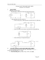
ENERGY MANAGEMENT HANDBOOKS phần 5 ppt
Bạn đang xem bản rút gọn của tài liệu. Xem và tải ngay bản đầy đủ của tài liệu tại đây (1.46 MB, 93 trang )
358 ENERGY MANAGEMENT HANDBOOK
Table 13.3 Lamp characteristics
———————————————————————————————————————————————————
Incandescent High-Pressure
Including Tungsten Compact Mercury Vapor Sodium Low-Pressure
Halogen Fluorescent Fluorescent (Self-ballasted) Metal Halide (Improved Color) Sodium
Wattages (lamp only) 15-1500 15-219 4-40 40-1000 175-1000 70-1000 35-180
———————————————————————————————————————————————————
Life (hr) 750-12,000 7,500-24,000 10,000-20,000 16,000-15,000 1,500-15,000 24,000 (10,000) 18,000
Effi cacy 15-25 55-100 50-80 50-60 80-100 75-140 Up to 180
(lumens/W) lamp only (20-25) (67-112)
Lumen maintenance Fair to excellent Fair to excellent Fair Very good Good Excellent Excellent
(good)
Color rendition Excellent Good to excellent Good to Poor to excellent Very good Fair Poor
excellent
Light direction control Very good to Fair Fair Very good Very good Very good Fair
excellent
Relight time Immediate Immediate Imm- 3 seconds 3-10 min. 10-20 min. Less than 1 min. Immediate
Comparative fi xture cost Low: simple Moderate Moderate Higher than Generally High High
fl uorescent higher than
mercury
Comparative operating High Lower than Lower than Lower than Lower than Lowest of HID Low
cost incandescent incandescent incandescent mercury types
———————————————————————————————————————————————————
Incandescent
The oldest electric lighting technology is the in-
candescent lamp. Incandescent lamps are also the least
effi cacious (have the lowest lumens per watt) and have
the shortest life. They produce light by passing a current
through a tungsten fi lament, causing it to become hot and
glow. As the tungsten emits light, it gradually evaporates,
eventually causing the fi lament to break. When this hap-
pens, the lamps is said to be “burned-out.”
Although incandescent sources are the least effi ca-
cious, they are still sold in great quantities because of
economies of scale and market barriers. Consumers still
purchase incandescent bulbs because they have low ini-
tial costs. However, if life-cycle cost analyses are used, in-
candescent lamps are usually more expensive than other
lighting systems with higher effi cacies.
Compact Fluorescent Lamps (CFLs)
Overview of CFLs:
Compact Fluorescent Lamps (CFLs) are energy effi cient,
long lasting replacements for some incandescent lamps.
CFLs (like all fl uorescent lamps) are composed of two
parts, the lamp and the ballast. The short tubular lamps
can last longer than 8,000 hours. The ballasts (plastic
component at the base of tube) usually last longer than
60,000 hours. Some CFLs can be purchased as self-bal-
lasted units, which “screw in” to an existing incandescent
socket. For simplicity, this chapter refers to a CFL as a
lamp and ballast system. CFLs are available in many
styles and sizes.
In most applications, CFLs are excellent replace-
ments for incandescent lamps. CFLs provide similar light
quantity and quality while only requiring about 20-30%
of the energy of comparable incandescent lamps. In ad-
dition, CFLs last 7 to 10 times longer than their incan-
descent counterparts. In many cases, it is cost-effective
to replace an entire incandescent fi xture with a fi xture
specially designed for CFLs.
The “New Technololgies” Section contains a more thorough
explanation of CFLs.
Fluorescent
Fluorescent lamps are the most common light
source for commercial interiors in the U.S. They are re-
peatedly specifi ed because they are relatively effi cient,
have long lamp lives and are available in a wide variety
of styles. For many years, the conventional fl uorescent
lamp used in offi ces has been the four-foot F40T12 lamp,
which is usually used with a magnetic ballast. However,
these lamps are being rapidly replaced by T8 or T5 lamps
with electronic ballasts.
The labeling system used by manufacturers may ap-
pear complex, however it is actually quite simple. For ex-
ample, with an F34T12 lamp, the “F” stands for fl uorescent,
the “34” means 34 watts, and the “T12” refers to the tube
thickness. Since tube thickness (diameter) is measured in
1/8 inch increments, a T12 is 12/8 or 1.5 inches in diameter.
A T8 lamp is 1 inch in diameter. Some lamp labels include
additional information, indicating the CRI and CCT. Usu-
LIGHTING 359
ally, CRI is indicated with one digit, like “8” meaning CRI
= 80. CCT is indicated by the two digits following, “35”
meaning 3500K. For example, a F32T8/841 label indicates
a lamp with a CRI = 80 and a CCT = 4100K. Alternatively,
the lamp manufacturer might label a lamp with a letter
code referring to a specifi c lamp color. For example, “CW”
to mean Cool White lamps with a CCT = 4100K.
Some lamps have “ES,” “EE” or “EW” printed on
the label. These acronyms attached at the end of a lamp
label indicate that the lamp is an energy-saving type.
These lamps consume less energy than standard lamps,
however they also produce less light.
Tri-phosphor lamps have a coating on the inside
of the lamp which improves performance. Tri-phosphor
lamps usually provide greater color rendition. A bi-phos-
phor lamp (T12 Cool White) has a CRI= 62. By upgrading
to a tri-phosphor lamp with a CRI = 75, occupants will
be able to distinguish colors better. Tri-phosphor lamps
are commonly specifi ed with systems using electronic
ballasts. Lamp fl icker and ballast humming are also sig-
nifi cantly reduced with electronically ballasted systems.
For these reasons, the visual environment and worker
productivity is likely to be improved.
There are many options to consider when choosing
fl uorescent lamps. Carefully check the manufacturers
specifi cations and be sure to match the lamp and ballast
to the application. Table 13.4 shows some of the specifi ca-
tions that vary between different lamp types.
The “New Technololgies” Section contains a more thor-
ough explanation of the various fl uorescent lamp systems
available today.
High Intensity Discharge (HID)
High-Intensity Discharge (HID) lamps are similar
to fl uorescent lamps because they produce light by dis-
charging an electric arc through a tube fi lled with gases.
HID lamps generate much more light, heat and pressure
within the arc tube than fl uorescent lamps, hence the
title “high intensity” discharge. Like incandescent lamps,
HIDs are physically small light sources, (point sources)
which means that refl ectors, refractors and light pipes can
be effectively used to direct the light. Although originally
developed for outdoor and industrial applications, HIDs
are also used in offi ce, retail and other indoor applica-
tions.
With a few exceptions, HIDs require time to warm
up and should not be turned ON and OFF for short inter-
vals. They are not ideal for certain applications because,
as point sources of light, they tend to produce more de-
fi ned shadows than non-point sources such as fl uorescent
tubes, which emit diffuse light.
Most HIDs have relatively high effi cacies and long
lamp lives, (5,000 to 24,000+ hours) reducing maintenance
re-lamping costs. In addition to reducing maintenance re-
quirements, HIDs have many unique benefi ts. There are
three popular types of HID sources (listed in order of in-
creasing effi cacy): Mercury Vapor, Metal Halide and High
Pressure Sodium. A fourth source, Low Pressure Sodium,
is not technically a HID, but provides similar quantities
of illumination and will be referred to as an HID in this
chapter. Table 13.3 shows that there are dramatic differ-
ences in effi cacy, CRI and CCT between each HID source
type.
Mercury Vapor
Mercury Vapor systems were the “fi rst generation”
HIDs. Today they are relatively ineffi cient, provide poor
CRI and have the most rapid lumen depreciation rate
of all HIDs. Because of these characteristics, other more
cost-effective HID sources have replaced mercury vapor
Table 13.4 Sample fl uorescent lamp specifi cations.
————————————————————————————————
MANUFACTURERS’ INFORMATION
F40T12CW F40T10 F32T8
Bi-phosphor Tri-phosphor Tri-phosphor
————————————————————————————————
CRI 62 83 83
CCT (K) 4,150 4,100 or 5,000 4,100 or 5,000
Initial lumens 3,150 3,700 3,050
Maintained lumens 2,205 2,960 2,287
Lumens per watt 55 74 71
Rated life (hrs) 24,000 48,000
†
20,000
Service life (hrs) 16,800 33,600
†
14,000
————————
†
This extended life is available from a specifi c lamp-ballast combination. Normal
T10 lamp lives are approximately 24,000 hours. Service life refers to the typical
lamp replacement life.
————————————————————————————————
360 ENERGY MANAGEMENT HANDBOOK
lamps in nearly all applications. Mercury Vapor lamps
provide a white-colored light which turns slightly green
over time. A popular lighting upgrade is to replace Mer-
cury Vapor systems with Metal Halide or High Pressure
Sodium systems.
Metal Halide
Metal Halide lamps are similar to mercury vapor
lamps, but contain slightly different metals in the arc
tube, providing more lumens per watt with improved
color rendition and improved lumen maintenance. With
nearly twice the effi cacy of Mercury Vapor lamps, Metal
Halide lamps provide a white light and are commonly
used in industrial facilities, sports arenas and other spac-
es where good color rendition is required. They are the
current best choice for lighting large areas that need good
color rendition.
High Pressure Sodium (HPS)
With a higher effi cacy than Metal Halide lamps,
HPS systems are an economical choice for most outdoor
and some industrial applications where good color
rendition is not required. HPS is common in parking
lots and produces a light golden color that allows some
color rendition. Although HPS lamps do not provide the
best color rendition, (or attractiveness) as “white light”
sources, they are adequate for indoor applications at
some industrial facilities. The key is to apply HPS in an
area where there are no other light source types available
for comparison. Because occupants usually prefer “white
light,” HPS installations can result with some occupant
complaints. However, when HPS is installed at a great
distance from metal halide lamps or fl uorescent systems,
the occupant will have no reference “white light” and
he/she will accept the HPS as “normal.” This technique
has allowed HPS to be installed in countless indoor gym-
nasiums and industrial spaces with minimal complaints.
Low Pressure Sodium
Although LPS systems have the highest effi cacy of
any commercially available HID, this monochromic light
source produces the poorest color rendition of all lamp
types. With a low CCT, the lamp appears to be “pumpkin
orange,” and all objects illuminated by its light appear
black and white or shades of gray. Applications are limit-
ed to security or street lighting. The lamps are physically
long (up to 3 feet) and not considered to be point sources.
Thus optical control is poor, making LPS less effective for
extremely high mounting heights.
LPS has become popular because of its extremely
high effi cacy. With up to 60% greater effi cacy than HPS,
LPS is economically attractive. Several cities, such as San
Diego, California, have installed LPS systems on streets.
Although there are many successful applications, LPS
installations must be carefully considered. Often lighting
quality can be improved by supplementing the LPS sys-
tem with other light sources (with a greater CRI).
13.2.3.2 Ballasts
With the exception of incandescent systems, nearly
all lighting systems (fl uorescent and HID) require a bal-
last. A ballast controls the voltage and current that is
supplied to lamps. Because ballasts are an integral com-
ponent of the lighting system, they have a direct impact
on light output. The ballast factor is the ratio of a lamp’s
light output to a reference ballast. General purpose fl uo-
rescent ballasts have a ballast factor that is less than one
(typically .88 for most electronic ballasts). Special ballasts
may have higher ballast factors to increase light output,
or lower ballast factors to reduce light output. As can be
expected, a ballast with a high ballast factor also con-
sumes more energy than a general purpose ballast.
Fluorescent
Specifying the proper ballast for fl uorescent light-
ing systems has become more complicated than it was 25
years ago, when magnetic ballasts were practically the
only option. Electronic ballasts for fl uorescent lamps have
been available since the early 1980s, and their introduc-
tion has resulted in a variety of options.
This section describes the two types of fl uorescent
ballasts: magnetic and electronic.
Magnetic
Magnetic ballasts are available in three primary
types.
• Standard core and coil
• High-effi ciency core and coil (Energy-Effi cient Bal-
lasts)
• Cathode cut-out or Hybrid
Standard core and coil magnetic ballasts are es-
sentially core and coil transformers that are relatively
ineffi cient at operating fl uorescent lamps. Although these
types of ballasts are no longer sold in the US, they still
exist in many facilities. The “high-effi ciency” magnetic
ballast can replace the “standard ballast,” improving the
system effi ciency by approximately 10%.
“Cathode cut-out” or “hybrid” ballasts are high-ef-
fi ciency core and coil ballasts that incorporate electronic
components that cut off power to the lamp cathodes after
the lamps are operating, resulting in an additional 2-watt
savings per lamp.
LIGHTING 361
Electronic
During the infancy of electronic ballast technology,
reliability and harmonic distortion problems hampered
their success. However, most electronic ballasts available
today have a failure rate of less than one percent, and
many distort harmonic current less than their magnetic
counterparts. Electronic ballasts are superior to magnetic
ballasts because they are typically 30% more energy ef-
fi cient, they produce less lamp fl icker, ballast noise, and
waste heat.
In nearly every fl uorescent lighting application,
electronic ballasts can be used in place of conventional
magnetic core and coil ballasts. Electronic ballasts im-
prove fluorescent system efficacy by converting the
standard 60 Hz input frequency to a higher frequency,
usually 25,000 to 40,000 Hz. Lamps operating on these
frequencies produce about the same amount of light,
while consuming up to 40% less power than a standard
magnetic ballast. Other advantages of electronic ballasts
include less audible noise, less weight, virtually no lamp
fl icker and dimming capabilities.
T12 and T8 ballasts are the most popular types of
electronic ballasts. T12 electronic ballasts are designed for
use with conventional (T12) fl uorescent lighting systems.
T8 ballasts offer some distinct advantages over other
types of electronic ballasts. They are generally more ef-
fi cient, have less lumen depreciation, and are available
with more options. T8 ballasts can operate one, two, three
or four lamps. Most T12 ballasts can only operate one,
two or three lamps. Therefore, one T8 ballast can replace
two T12 ballasts in a 4 lamp fi xture.
Some electronic ballasts are parallel-wired, so that
when one lamp burns out, the remaining lamps in the
fi xture will continue to operate. In a typical magnetic, (se-
ries-wired system) when one component fails, all lamps
in the fi xture shut OFF. Before maintenance personnel can
relamp, they must fi rst diagnose which lamp failed. Thus
the electronically ballasted system will reduce time to
diagnose problems, because maintenance personnel can
immediately see which lamp failed.
Parallel-wired ballasts also offer the option of re-
ducing lamps per fi xture (after the retrofi t) if an area is
over-illuminated. This option allows the energy manager
to experiment with different confi gurations of lamps in
different areas. However, each ballast operates best when
controlling the specifi ed number of lamps.
Due to the advantages of electronically ballasted
systems, they are produced by many manufacturers and
prices are very competitive. Due to their market penetra-
tion, T8 systems (and replacement parts) are more likely
to be available, and at lower costs.
HID
As with fl uorescent systems, High Intensity Dis-
charge lamps also require ballasts to operate. Although
there are not nearly as many specifi cation options as with
fl uorescent ballasts, HID ballasts are available in dim-
mable and bi-level light outputs. Instant restrike systems
are also available.
Capacitive Switching HID Fixtures
Capacitive switching or “bi-level” HID fi xtures are
designed to provide either full or partial light output
based on inputs from occupancy sensors, manual switch-
es or scheduling systems. Capacitive-switched dimming
can be installed as a retrofi t to existing fi xtures or as a
direct fi xture replacement. Capacitive switching HID up-
grades can be less expensive than installing a panel-level
variable voltage control to dim the lights, especially in
circuits with relatively few fi xtures.
The most common applications of capacitive switch-
ing are athletic facilities, occupancy-sensed dimming in
parking lots and warehouse aisles. General purpose trans-
mitters can be used with other control devices such as tim-
ers and photosensors to control the bi-level fi xtures. Upon
detecting motion, the occupancy sensor sends a signal to
the bi-level HID ballasts. The system will rapidly bring the
light levels from a standby reduced level to about 80 per-
cent of full output, followed by the normal warm-up time
between 80 and 100 percent of full light output.
Depending of the lamp type and wattage, the
standby lumens are roughly 15-40 percent of full output
and the standby wattage is 30-60 percent of full wattage.
When the space is unoccupied and the system is dimmed,
you can achieve energy savings of 40-70 percent.
13.2.3.3 Fixtures (aka Luminaires)
A fi xture is a unit consisting of the lamps, ballasts,
reflectors, lenses or louvers and housing. The main
function is to focus or spread light emanating from the
lamp(s). Without fi xtures, lighting systems would appear
very bright and cause glare.
Fixture Effi ciency
Fixtures block or refl ect some of the light exiting the
lamp. The effi ciency of a fi xture is the percentage of lamp
lumens produced that actually exit the fi xture in the in-
tended direction. Effi ciency varies greatly among differ-
ent fi xture and lamp confi gurations. For example, using
four T8 lamps in a fi xture will be more effi
cient than using
four T12 lamps because the T8 lamps are thinner, allow-
ing more light to “escape” between the lamps and out of
the fi xture. Understanding fi xtures is important because a
lighting retrofi t may involve changing some components
362 ENERGY MANAGEMENT HANDBOOK
Figure 13.3 Higher shielding angles for improved glare
control.
of the fi xture to improve the effi ciency and deliver more
light to the task.
The Coeffi cient of Utilization (CU) is the percent of
lumens produced that actually reach the work plane. The
CU incorporates the fi xture effi ciency, mounting height,
and refl ectances of walls and ceilings. Therefore, improv-
ing the fi xture effi ciency will improve the CU.
Refl ectors
Installing refl ectors in most fi xtures can improve its
effi ciency because light leaving the lamp is more likely
to “refl ect” off interior walls and exit the fi xture. Because
lamps block some of the light refl ecting off the fi xture in-
terior, refl ectors perform better when there are less lamps
(or smaller lamps) in the fi xture. Due to this fact, a com-
mon fi xture upgrade is to install refl ectors and remove
some of the lamps in a fi xture. Although the fi xture effi -
ciency is improved, the overall light output from each fi x-
ture is likely to be reduced, which will result in reduced
light levels. In addition, refl ectors will redistribute light
(usually more light is refl ected down), which may create
bright and dark spots in the room. Altered light levels
and different distributions may be acceptable, however
these changes need to be considered.
To ensure acceptable performance from refl ectors,
conduct a trial installation and measure “before” and
“after” light levels at various locations in the room. Don’t
compare an existing system, (which is dirty, old and con-
tains old lamps) against a new fi xture with half the lamps
and a clean refl ector. The light levels may appear to be
adequate, or even improved. However, as the new system
ages and dirt accumulates on the surfaces, the light levels
will drop.
A variety of refl ector materials are available: highly
refl ective white paint, silver fi lm laminate, and anodized
aluminum. Silver fi lm laminate usually has the highest
refl ectance, but is considered less durable. Be sure to
evaluate the economic benefi ts of your options to get the
most “bang for your buck.”
In addition to installing refl ectors within fi
xtures,
light levels can be increased by improving the refl ectivity
of the room’s walls, fl oors and ceilings. For example, by
covering a brown wall with white paint, more light will
be refl ected back into the workspace, and the Coeffi cient
of Utilization is increased.
Lenses and Louvers
Most indoor fi xtures use either a lens or louver to
prevent occupants from directly seeing the lamps. Light
that is emitted in the shielding angle or “glare zone”
(angles above 45
o
from the fi xture’s vertical axis) can
cause glare and visual discomfort, which hinders the
occupant’s ability to view work surfaces and computer
screens. Lenses and louvers are designed to shield the
viewer from these uncomfortable, direct beams of light.
Lenses and louvers are usually included as part of a fi x-
ture when purchased, and they can have a tremendous
impact on the VCP of a fi xture.
Lenses are sheets of hard plastic (either clear or
milky white) that are located on the bottom of a fi xture.
Clear, prismatic lenses are very effi cient because they trap
less light within the fi xture. Milky-white lenses are called
“diffusers” and are the least effi cient, trapping a lot of
the light within the fi xture. Although diffusers have been
routinely specifi ed for many offi ce environments, they
have one of the lowest VCP ratings.
Louvers provide superior glare control and high
VCP when compared to most lenses. As Figure 13.3
shows, a louver is a grid of plastic “shields” which blocks
some of the horizontal light exiting the fi xture. The most
common application of louvers is to reduce the fi xture
glare in sensitive work environments, such as in rooms
with computers. Parabolic louvers usually improve the
VCP of a fi xture, however effi ciency is reduced because
more light is blocked by the louver. Generally, the smaller
the cell, the greater the VCP and less the effi ciency. Deep-
cell parabolic louvers offer a better combination of VCP
and effi ciency, however deep-cell louvers require deep
fi xtures, which may not fi t into the ceiling plenum space.
Table 13.5 shows the effi ciency and VCP for various
lenses and louvers. VCP is usually inversely related to
fi xture effi ciency. An exception is with the milky-white
diffusers, which have low VCP and low effi ciency.
Light Distribution/Mounting Height
Fixtures are designed to direct light where it is need-
ed. Various light distributions are possible to best suit any
visual environment. With “direct lighting,” 90-100% of
the light is directed downward for maximum use. With
“indirect lighting,” 90-100% of the light is directed to
the ceilings and upper walls. A “semi-indirect” system
LIGHTING 363
distributes 60-90% down, with the remainder upward.
Designing the lighting system should incorporate the dif-
ferent light distributions of different fi xtures to maximize
comfort and visual quality.
Fixture mounting height and light distribution are
presented together since they are interactive. HID systems
are preferred for high mounting heights since the lamps
are physically small, and refl ectors can direct light down-
ward with a high degree of control. Fluorescent lamps are
physically long and diffuse sources, with less ability to
control light at high mounting heights. Thus fl uorescent
systems are better for low mounting heights and/or areas
that require diffuse light with minimal shadows.
Generally, “high-bay” HID fi xtures are designed for
mounting heights greater than 20 feet high. “High-bay”
fi xtures usually have refl ectors and focus most of their
light downward. “Low-bay” fi xtures are designed for
mounting heights less than 20 feet and use lenses to direct
more light horizontally.
HID sources are potential sources of direct glare
since they produce large quantities of light from physical-
ly small lamps. The probability of excessive direct glare
may be minimized by mounting fi xtures at suffi cient
heights. Table 13.6 shows the minimum mounting height
recommended for different types of HID systems.
13.2.3.4 Exit Signs
Recent advances in exit sign systems have created
attractive opportunities to reduce energy and maintenance
costs. Because emergency exit signs should operate 24
hours per day, energy savings quickly recover retrofi t costs.
There are generally two options, buying a new exit sign, or
retrofi tting the existing exit sign with new light sources.
Most retrofi t kits available today contain adapters
that screw into the existing incandescent sockets. Instal-
lation is easy, usually requiring only 15 minutes per sign.
However, if a sign is severely discolored or damaged,
buying a new sign might be required in order to maintain
illuminance as required by fi re codes.
Basically, there are fi ve upgrade technologies: Com-
pact Fluorescent Lamps (CFLs), incandescent assemblies,
Light Emitting Diodes (LED), Electroluminescent panels,
and Self Luminous Tubes.
Replacing incandescent sources with compact fl uo-
rescent lamps was the “fi rst generation” exit sign upgrade.
Most CFL kits must be hard-wired and can not simply
screw into an existing incandescent socket. Although CFL
kits are a great improvement over incandescent exit signs,
more technologically advanced upgrades are available
that offer reduced maintenance costs, greater effi cacy and
fl exibility for installation in low (sub-zero) temperature
environments.
As Table 13.7 shows, LED upgrades are the most
cost-effective because they consume very little energy,
and have an extremely long life, practically eliminating
maintenance.
Table 13.5 Luminaire effi ciency and VCP.
—————————————————————————
Shielding Material Luminaire Visual Comfort
Effi ciency Probability
(%) (VCP)
—————————————————————————
Clear Prismatic Lens 60-70 50-70
Low Glare Clear Lens 60-75 75-85
Deep-Cell Parabolic Louver 50-70 75-95
Translucent Diffuser 40-60 40-50
Small-Cell Parabolic Louver 35-45 99
—————————————————————————
Table 13.6 Minimum mounting heights for HIDs
—————————————————————————
Lamp Type feet above ground
—————————————————————————
400 W Metal Halide 16
1000 W Metal Halide 20
200 W High Pressure Sodium 15
250 W High Pressure Sodium 16
400 W High Pressure Sodium 18
1000 W High Pressure Sodium 26
—————————————————————————
Table 13.7 Exit sign upgrades.
————————————————————————————————————
Light Source Watts Life Replacement
————————————————————————————————————
Incandescent (Long Life) 40 8 months lamps
Compact Fluorescent 10 1.7 years lamps
Incandescent Assembly 8 3 + years light source
Light Emitting Diode (LED) <4 >25 light source
Electroluminescent 1 8+ years panel
Self luminous (Tritium) 0 10-20 years luminous tubes
————————————————————————————————————
364 ENERGY MANAGEMENT HANDBOOK
Another low-maintenance upgrade is to install a
“rope” of incandescent assemblies. These low-voltage “lu-
minous ropes” are an easy retrofi t because they can screw
into existing sockets like LED retrofi t kits. However, the
incandescent assemblies create bright spots which are vis-
ible through the transparent exit sign and the non-uniform
glow is a noticeable change. In addition, the incandescent
assemblies don’t last nearly as long as LEDs.
Although electroluminescent panels consume less
than one watt, light output rapidly depreciates over
time. These self-luminous sources are obviously the most
energy-effi cient, consuming no electricity. However the
spent tritium tubes, which illuminate the unit, must be
disposed of as a radioactive waste, which will increase
over-all costs.
13.2.3.5 Lighting Controls
Lighting controls offer the ability for systems to be
turned ON and OFF either manually or automatically.
There are several control technology upgrades for light-
ing systems, ranging from simple (installing manual
switches in proper locations) to sophisticated (installing
occupancy sensors).
Switches
The standard manual, single-pole switch was the
fi rst energy conservation device. It is also the simplest
device and provides the least options. One negative
aspect about manual switches is that people often for-
get to turn them OFF. If switches are far from room
exits or are diffi cult to fi nd, occupants are more likely
to leave lights ON when exiting a room.
1
Occupants
do not want to walk through darkness to fi nd exits.
However, if switches are located in the right locations,
with multiple points of control for a single circuit,
occupants find it easier to turn systems OFF. Once
occupants get in the habit of turning lights OFF upon
exit, more complex systems may not be necessary. The
point is: switches can be great energy conservation
devices as long as they are convenient to use them.
Another opportunity for upgrading controls ex-
ists when lighting systems are designed such that all
circuits in an area are controlled from one switch, yet
not all circuits need to be activated. For example, a
college football stadium’s lighting system is designed
to provide enough light for TV applications. However,
this intense amount of light is not needed for regular
practice nights or other non-TV events. Because the
lights are all controlled from one switch, every time
the facility is used all the lights are turned ON. By
dividing the circuits and installing one more switch
to allow the football stadium to use only 70% of its
lights during practice nights, signifi cant energy sav-
ings are possible.
Generally, if it is not too diffi cult to re-circuit a
poorly designed lighting system, additional switches can
be added to optimize the lighting controls.
Time Clocks
Time clocks can be used to control lights when their
operation is based on a fi xed operating schedule. Time
clocks are available in electronic or mechanical styles.
However, regular check-ups are needed to ensure that
the time clock is controlling the system properly. After
a power loss, electronic timers without battery backups
can get off schedule—cycling ON and OFF at the wrong
times. It requires a great deal of maintenance time to reset
isolated time clocks if many are installed.
Photocells
For most outdoor lighting applications, photocells
(which turn lights ON when it gets dark, and off when
suffi cient daylight is available) offer a low-maintenance
alternative to time clocks. Unlike time clocks, photocells
are seasonally self-adjusting and automatically switch
ON when light levels are low, such as during rainy days.
A photocell is inexpensive and can be installed on each
fi xture, or can be installed to control numerous fi xtures
on one circuit. Photocells can also be effectively used in-
doors, if daylight is available through skylights.
Photocells have worked well in almost any climate,
however they should be aimed north (in the northern
hemisphere) to “view” the refl ected light of the north sky.
This way they are not biased by the directionality of east/
west exposure or degraded by intense southern exposure.
Photocells should also be cleaned when fi xtures are re-
lamped. Otherwise, dust will accumulate on the photodi-
ode aperture, causing the controls to always perceive it is
a cloudy day, and the lights will stay ON.
The least expensive type of photocell uses a cadmi-
um sulfi de cell, but these cells lose sensitivity after being
in service for a few years by being degraded from their
exposure to sunlight. This decreases savings by keeping
exterior lighting on longer than required. To avoid this
situation, cadmium sulfi de cells can be replaced with elec-
tronic types that do not lose sensitivity over time. These
electronic photocells use solid-state, silicon phototransis-
tors or photodiodes, which last longer as evidenced by
their longer warranties—up to 6 years—and can easily
pay back before that time with energy and labor savings.
Photocells combined with Dimmable
Ballasts to allow Daylight Harvesting
Daylight harvesting is a control strategy that can be
LIGHTING 365
applied where diffuse daylight can be used effectively
to light interior spaces. There is a widespread misunder-
standing that daylighting can only be done in areas where
there is a predominance of sunny, clear days, such as
California or Arizona. In fact, many places with over 50%
cloudy days can cost-effectively use daylight controls.
Daylight harvesting employs strategically located
photo-sensors and electronic dimming ballasts. To ef-
fectively apply this strategy requires more knowledge
than just plugging a sensor into a dimming ballast. Photo-
sensors and dimming ballasts form a control system that
controls the light level according to the daylight level. The
fl uorescent lighting is dimmed to maintain a band of light
level when there is suffi cient daylight present in the space.
The output is changed gradually by a fade control so oc-
cupants are not disturbed by rapid changes in light level.
Lumen Depreciation Compensation
(an additional benefi t of a Daylight Harvesting System)
Lighting systems are usually over-designed to
compensate for light losses that normally occur during
the life time of the system. Alternatively, the “lumen
depreciation compensation strategy” allows the design
light level to be met without over-designing, thereby
providing a more effi cient lighting system. The control
system works in a way similar to daylight harvesting
controls. A photo-sensor detects the actual light level and
provides a low-voltage signal to electronic dimming bal-
lasts to adjust the light level. When lamps are new and
room surfaces are clean, less power is required to provide
the design light level. As lamps depreciate in their light
output and as surfaces become dirty, the input power and
light level is increased gradually to compensate for these
sources of light loss. Some building management systems
accomplish this control by using a depreciation algorithm
to adjust the output of the electronic ballasts instead of
relying on photo-sensors.
Occupancy Sensors
Occupancy sensors save energy by turning off
lights in spaces that are unoccupied. When the sensor
detects motion, it activates a control device that turns
ON a lighting system. If no motion is detected within a
specifi ed period, the lights are turned OFF until motion
is sensed again. With most sensors, sensitivity (the abil-
ity to detect motion) and the time delay (difference in
time between when sensor detects no motion and lights
go OFF) are adjustable. Occupancy sensors are pro-
duced in two primary types: Ultrasonic (US) and Pas-
sive Infrared (PIR). Dual-Technology (DT) sensors, that
have both ultrasonic and passive infrared detectors, are
also available. Table 13.8 shows the estimated percent
energy savings from occupancy sensor installation for
various locations.
US and PIR sensors are available as wall-switch
sensors, or remote sensors such as ceiling mounted or
outdoor commercial grade units. With remote sensors,
a low-voltage wire connects each sensor to an electrical
relay and control module, which operates on common
voltages. With wall-switch sensors, the sensor and control
module are packaged as one unit. Multiple sensors and/
or lighting circuits can be linked to one control module
allowing fl exibility for optimum design.
Wall-switch sensors can replace existing manual
switches in small areas such as offi ces, conference rooms,
and some classrooms. However, in these applications, a
manual override switch should be available so that the
lights can be turned OFF for slide presentations and other
visual displays. Wall-switch sensors should have an un-
obstructed coverage pattern (absolutely necessary for PIR
sensors) of the room it controls.
Ceiling-mounted units are appropriate in corridors,
rest rooms, open offi ce areas with partitions and any
space where objects obstruct the line of sight from a wall-
mounted sensor location. Commercial grade outdoor units
can also be used in indoor warehouses and large aisles.
Sensors designed for outdoor use are typically heavy duty,
and usually have the adjustable sensitivities and coverage
patterns for maximum fl exibility. Table 13.9 indicates the
appropriate sensors for various applications.
Ultrasonic Sensors (US)
Ultrasonic sensors transmit and receive high-fre-
quency sound waves above the range of human hearing.
The sound waves bounce around the room and return
to the sensor. Any motion within the room distorts the
sound waves. The sensor detects this distortion and
signals the lights to turn ON. When no motion has been
detected over a user-specifi ed time, the sensor sends a
signal to turn the lights OFF. Because ultrasonic sensors
Table 13.8 Estimated % savings
from occupancy sensors.
—————————————————————————
Application Energy Savings
—————————————————————————
Offi ces (Private) 25-50%
Offi ces (Open Spaces) 20-25%
Rest Rooms 30-75%
Corridors 30-40%
Storage Areas 45-65%
Meeting Rooms 45-65%
Conference Rooms 45-65%
Warehouses 50-75%
—————————————————————————
366 ENERGY MANAGEMENT HANDBOOK
need enclosed spaces (for good sound wave echo refl ec-
tion), they can only be used indoors and perform better
if room surfaces are hard, where sound wave absorption
is minimized. Ultrasonic sensors are most sensitive to
motion toward or away from the sensor. Applications in-
clude rooms with objects that obstruct the sensor’s line of
sight coverage of the room, such as restroom stalls, locker
rooms and storage areas.
Passive Infrared Sensors (PIR)
Passive Infrared sensors detect differences in infra-
red energy emanating in the room. When a person moves,
the sensor “sees” a heat source move from one zone to
the next. PIR sensors require an unobstructed view, and
as distance from the sensor increases, larger motions are
necessary to trigger the sensor. Applications include open
plan offi ces (without partitions), classrooms and other
areas that allow a clear line of sight from the sensor.
Dual-Technology Sensors (DT)
Dual-Technology (DT) sensors combine both US
and PIR sensing technologies. DT sensors can improve
sensor reliability and minimize false switching. However,
these types of sensors are still only limited to applications
where ultrasonic sensors will work.
Occupancy Sensor Effect on Lamp Life
Occupancy Sensors can cause rapid ON/OFF
switching which reduces the life of certain fl uorescent
lamps. Offi ces without occupancy sensors usually have
lights constantly ON for approximately ten hours per day.
After occupancy sensors are installed, the lamps may be
turned ON and OFF several times per day. Several labo-
ratory tests have shown that some fl uorescent lamps lose
about 25% of their life if turned OFF and ON every three
hours. Although occupancy sensors may cause lamp life
to be reduced, the annual burning hours also decreases.
Therefore, in most applications, the time period until re-
lamp will not increase. However, due to the laboratory
results, occupancy sensors should be carefully evaluated
if the lights will be turned ON and OFF rapidly. The lon-
ger the lights are left OFF, the longer lamps will last.
The frequency at which occupants enter a room
makes a difference in the actual percent time savings pos-
sible. Occupancy sensors save the most energy when ap-
plied in rooms that are not used for long periods of time.
If a room is frequently used and occupants re-enter a room
before the lights have had a chance to turn OFF, no energy
will be saved. Therefore, a room that is occupied once
every three hours will be more appropriate for occupancy
sensors than a room occupied once every three minutes,
even though the percent vacancy time is the same.
Occupancy Sensors and HIDs
Although occupancy sensors were not primarily de-
veloped for HIDs, some special HID ballasts (bi-level) of-
fer the ability to dim and re-light lamps quickly. Another
term for bi-level HID technology is Capacitive Switching
HID Fixtures, which are discussed in the HID Ballast Sec-
tion.
Lighting Controls via a Facility Management System
When lighting systems are connected to a Facility
Management System (FMS), greater control options can
be realized. The FMS could control lights (and other
equipment, i.e. HVAC) to turn OFF during non-working
Table 13.9 Occupancy sensor applications.
Private Large Partitioned Conference Rest Closets/ Hallways Warehouse
Offi ce Open Offi ce Room Room Copy Corridors Aisles
Sensor Offi ce Plan Room Areas
Technology Plan
———————————————————————————————————————————————————
US Wall Switch • • • •
US Ceiling Mount • • • • • •
IR Wall Switch • • •
IR Ceiling Mount • • • • •
US Narrow View •
IR High Mount Narrow View • •
Corner Mount Wide- • •
View Technology Type
LIGHTING 367
hours, except when other sensors indicate that a space
is occupied. These sensors include standard occupancy
sensors or a card access system, which could indicate
which employee is in a particular part of the facility. If
the facility is “smart,” it will know where the employee
works and control the lights and other systems in that
area. By wiring all systems to the FMS, there is a greater
ability to integrate technologies for maximum perfor-
mance and savings. For example, an employee can control
lights by entering a code into the telephone system or a com-
puter network.
Specialized controls for individual work environ-
ments (offi ces or cubicles) are also available. These sys-
tems use an occupancy sensor to regulate lights, other
electronic systems (and even HVAC systems) in an energy
effi cient manner. In some systems, remote controls allow
the occupant to regulate individual lighting and HVAC
systems. These customized systems have allowed some
organizations to realize individual productivity gains via
more effective and aesthetic work space environments.
13.3 PROCESS TO IMPROVE
LIGHTING EFFICIENCY
The three basic steps to improving the effi ciency of
lighting systems:
1. Identify necessary light quantity and quality to per-
form visual task.
2. Increase light source effi ciency if occupancy is fre-
quent.
3. Optimize lighting controls if occupancy is infre-
quent.
Step 1, identifying the proper lighting quantity and
quality is essential to any illuminated space. However,
steps 2 & 3 are options that can be explored individually
or together. Steps 2 & 3 can both be implemented, but of-
ten the two options are economically mutually exclusive.
If you can turn OFF a lighting system for the majority
of time, the extra expense to upgrade lighting sources
is rarely justifi ed. Remember, light source upgrades will
only save energy (relative to the existing system) when
the lights are ON.
13.3.1 Identify necessary light quantities
and qualities to perform tasks.
Identifying the necessary light quantities for a task
is the fi rst step of a lighting retrofi t. Often this step is
overlooked because most energy managers try to mimic
the illumination of an existing system, even if it is over-il-
luminated and contains many sources of glare. For many
years, lighting systems were designed with the belief that
no space can be over-illuminated. However, the “more
light is better” myth has been dispelled and light levels
recommended by the IES declined by 15% in hospitals,
17% in schools, 21% in offi ce buildings and 34% in retail
buildings.
2
Even with IES’s adjustments, there are still
many excessively illuminated spaces in use today. Energy
managers can reap remarkable savings by simply rede-
signing a lighting system so that the proper illumination
levels are produced.
Although the number of workplane footcandles are
important, the occupant needs to have a contrast so that
he can perform a task. For example, during the daytime
your car headlights don’t create enough contrast to be
noticeable. However, at night, your headlights provide
enough contrast for the task. The same amount of light
is provided by the headlights during both periods, but
daylight “washes out” the contrast of the headlights.
The same principle applies to offi ces, and other
illuminated spaces. For a task to appear relatively
bright, objects surrounding that task must be relatively
dark. For example, if ambient light is excessive (150
fc) the occupant’s eyes will adjust to it and perceive it
as the “norm.” However when the occupant wants to
focus on something he/she may require an additional
light to accent the task (at 200 fc). This excessively illu-
minated space results in unnecessary energy consump-
tion. The occupant would see better if ambient light
was reduced to 30-40 fc and the task light was used to
accent the task at 50 fc. As discussed earlier, excessive
illumination is not only wasteful, but it can reduce
the comfort of the visual environment and decrease
worker productivity.
After identifying the proper quantity of light, the
proper quality must be chosen. The CRI, CCT and VCP
must be specifi ed to suit the space.
13.3.2 Increase Source Effi cacy
Increasing the source effi cacy of a lighting system
means replacing or modifying the lamps, ballasts and/or
fi xtures to become more effi cient. In the past, the term
“source” has been used to imply only the lamp of a sys-
tem. However, due to the inter-relationships between
components of modern lighting systems, we also con-
sider ballast and fi xture retrofi ts as “source upgrades.”
Thus increasing the effi cacy simply means getting more
lumens per watt out of lighting system. For example, to
increase the source effi cacy of a T12 system with a mag-
netic ballast, the ballast and lamps could be replaced with
T8 lamps and an electronic ballast, which is a more effi ca-
cious (effi cient) system.
Another retrofi t that would increase source effi cacy
368 ENERGY MANAGEMENT HANDBOOK
would be to improve the fi xture effi ciency by installing
refl ectors and more effi cient lenses. This retrofi t would
increase the lumens per watt, because with refl ectors and
effi cient lenses, more lumens can escape the fi xture, while
the power supplied remains constant.
Increasing the effi ciency of a light source is one of
the most popular types of lighting retrofi ts because en-
ergy savings can almost be guaranteed if the new system
consumes less watts than the old system. With reduced
lighting load, electrical demand savings are also usually
obtained. In addition, lighting quality can be improved
by specifying sources with higher CRI and improved
performance. These benefi ts allow capital improvements
for lighting systems that pay for themselves through in-
creased profi ts.
Task lighting
As a subset of Increasing Source Effi cacy, “Task
lighting” or “Task/Ambient” lighting techniques involve
improving the effi ciency of lighting in an entire work-
place, by replacing and relocating lighting systems. Task
lighting means retrofi tting lighting systems to provide
appropriate illumination for each task. Usually, this re-
sults in a reduction of ambient light levels, while main-
taining or increasing the light levels on a particular task.
For example, in an offi ce the light level needed on a desk
could be 75 fc. The light needed in aisles is only 20 fc.
Traditional uniform lighting design would create a work-
place where ambient lighting provides 75 fc throughout
the entire workspace. Task lighting would create an envi-
ronment where each desk is illuminated to 75 fc, and the
aisles only to 20 fc. Figure 13.4 shows a typical application
of Task/Ambient lighting.
Task lighting upgrades are a model of energy ef-
fi ciency, because they only illuminate what is necessary.
Task lighting designs are best suited for offi ce environ-
ments with VDTs and/or where modular furniture can
incorporate task lighting under shelves. Alternatively,
moveable desk lamps may be used for task illumination.
Savings result when the energy saved from reducing am-
bient light levels exceeds the energy used for task lights.
In most work spaces, a variety of visual tasks are
performed, and each employee has lighting preferences.
Most workers prefer lighting systems designed with task
lighting because it is fl exible and allows individual con-
trol. For example, older workers may require greater light
levels than young workers. Identifying task lighting op-
portunities may require some creativity, but the potential
dollar savings can be enormous.
Task lighting techniques are also applicable in in-
dustrial facilities—for example, high intensity task lights
can be installed on fork trucks (to supplement headlights)
for use in rarely occupied warehouses. With this system,
the entire warehouse’s lighting can be reduced, saving a
large amount of energy.
13.3.3 Optimize Lighting Controls
The third step of lighting energy management is to
investigate optimizing lighting controls. As shown earlier,
improving the effi ciency of a lighting system can save a
percentage of the energy consumed while the system is op-
erating. However, sophisticated controls can turn systems
OFF when they are not needed, allowing energy savings
to accumulate quickly. The Electric Power Research Insti-
tute (EPRI) reports that spaces in an average offi ce build-
ing may only be occupied 60-75% of the time, although
the lights may be ON for the entire 10 hour day
3
. Lighting
controls include switches, time clocks, occupancy sensors
and other devices that regulate a lighting system. These
systems are discussed in Section 13.2.3, Lighting System
Components.
13.4 MAINTENANCE
13.4.1 Isolated Systems
Most lighting manuals prescribe specialized tech-
nologies to effi ciently provide light for particular tasks.
An example is dimmable ballasts. For areas that have
suffi cient daylight, dimmable ballasts can be used with
integrated circuitry to reduce energy consumption dur-
ing peak periods. Still, though there may be some shed-
ding of lighting load along the perimeter, these energy
cost savings may not represent a great percentage of the
building’s total lighting load. Further, applications of
specialized technologies (such as dimmable ballasts) may
be dispersed and isolated in several buildings, which can
become a complex maintenance challenge, even if lamp
types and locations are recorded properly. If maintenance
personnel need to make additional site visits to get the
Figure 13.4 Task/ambient lighting.
LIGHTING 369
right equipment to re-lamp or “fine-tune” special sys-
tems, the labor costs may exceed the energy cost savings.
In facilities with low potential for energy cost sav-
ings, facility managers may not want to spend a great
deal of time monitoring and “fi ne-tuning” a lighting
system if other maintenance concerns need attention. If
a specialized lighting system malfunctions, repair may
require special components, that may be expensive and
more diffi cult to install. If maintenance cannot effectively
repair the complex technologies, the systems will fail
and occupant complaints will increase. Thus the isolated,
complex technology that appeared to be a unique solu-
tion to a particular lighting issue is often replaced with a
system that is easy to maintain.
In addition to the often eventual replacement of
technologies that are diffi cult to maintain, well intended
repairs to the system may accidentally result in “snap-
back.” “Snap-back” is when a specialized or isolated
technology is accidentally replaced with a common tech-
nology within the facility. For example, if dimmable bal-
lasts only represent 10% of the building’s total ballasts,
maintenance personnel might not keep them in stock.
When replacement is needed, the maintenance personnel
may accidentally install a regular ballast. Thus, the light-
ing retrofi t has “snapped back” to its original condition.
The above arguments are not meant to “shoot
down” the application of all new technologies. However,
new technologies usually bring new problems. The au-
thors ask that the energy manager carefully consider the
maintenance impact when evaluating an isolated technol-
ogy. Once again, all lighting systems depend on regular
maintenance.
13.4.2 Maintaining System Performance
As with most manufactured products, lighting sys-
tems lose performance over time. This degradation can
be the result of Lamp Lumen Depreciation (LLD), Fixture
Dirt Depreciation (LDD), Room Surface Dirt Depreciation
(RSDD), and many other factors. Several of these factors
can be recovered to maintain performance of the lighting
system. Figure 13.5 shows the LLD for various types of
lighting systems
Lamp Lumen Depreciation occurs because as the
lamp ages, its performance degrades. LLD can be accel-
erated if the lamp is operated in harsh environments, or
the system is subjected to conditions for which it was not
designed. For example, if a fl uorescent system is turned
ON and OFF every minute, the lamps and ballasts will
not last as long. Light loss due to lamp lumen deprecia-
tion can be recovered by re-lamping the fi xture.
Fixture Dirt Depreciation and Room Surface Dirt
Depreciation block light and can reduce light levels.
However, these factors can be minimized by cleaning
surfaces and minimizing dust. The magnitude of these
factors is dependent on each room, thus recommended
cleaning intervals can vary. Generally it is most economi-
cal to clean fi xtures when re-lamping.
13.4.3 Group Re-lamping
Most companies replace lamps when someone notic-
es a lamp is burned out. In a high rise building, this could
become a full-time job, running from fl oor to fl oor, offi ce
to offi ce, disrupting work to open a fi xture and replace a
lamp. However, in certain cases, it is less costly to group
re-lamp on a pre-determined date. Group relamping can
Figure 13.5 Lamp lumen depreciation (LLD).
370 ENERGY MANAGEMENT HANDBOOK
Table 13.10 Group relamping example: 1,000 3-Lamp T8 Lensed troffers
————————————————————————————————————
Spot Relamping Group Relamping
(on burn-out) (@ 70% rated life)
————————————————————————————————————
Relamp cycle 20,000 hours 14,000 hours
Avg. relamps/year 525 relamps/yr 750 relamps/yr (group)
52 relamps/yr (spot)
Avg. material cost/year $1,050/yr $1,604/yr
Lamp disposal @ 0.50 ea. $236/yr $375/yr
Avg. labor cost/year $3,150/yr $1,437/yr
TOTAL EXPENSES: $4,463/yr $3,416/yr
Assumptions: Labor: $6.00/lamp $1.50/lamp
Material: $2.00/lamp $2.00/lamp
Operation: 3,500 hr/yr 3,500 hr/yr
————————————————————————————————————
be cost-effective due to economies of scale. Replacing all
lamps at one time can be more effi cient than relamping
“one at a time.” In addition, bulk purchasing may also
yield savings. The rule of thumb is: group relamp at 50%
to 70% of the lamp’s rated life. However, depending on
site-specifi c factors and the lumen depreciation of the
lighting system, relamping interval may vary.
The facility manager must evaluate their own build-
ing, and determine the appropriate relamp interval by
observing when lamps start to fail. Due to variations in
power voltages (spikes, surges and low power), lamps
may have different operating characteristics and lives
from one facility to another. It is important to maintain
records on lamp and ballast replacements and determine
the most appropriate relamping interval. This also helps
keep track of maintenance costs, labor needs and bud-
gets.
Group relamping is the least costly method to
relamp due to reduced time and labor costs. For example,
Table 13.10 shows the benefi ts of group relamping. As
more states adopt legislation requiring special disposal
of lighting systems, group relamping in bulk may offer
reduced disposal costs due to large volumes of material.
13.4.4 Disposal Costs
Disposal costs and regulations for lighting systems
vary from state to state. These expenses should be in-
cluded in an economic analysis of any retrofi t. If proper
disposal regulations are not followed, the EPA could
impose fi nes and hold the violating company liable for
environmental damage in the future.
13.5 NEW TECHNOLOGIES & PRODUCTS
1
The energy effi cient lighting market is extremely
competitive, forcing manufacturers to develop new
products to survive. The development is so rapid, it is
challenging to “keep up” with all the latest technologies.
This chapter describes the proven technologies, however
it is good idea to evaluate the latest developments before
implementing a lighting system.
13.5.1 Fluorescent Ballasts
Miniaturization of electronic ballasts has been made
possible by the use of integrated circuits and surface-
mount technologies. The new ballasts are smaller, thinner
and lighter.
Low Profi le Housing
The familiar “brick” shape and weight of ballasts
will soon be gone. Reduced parts count and surface
mount technology have reduced the size of ballasts as
well as improved their reliability. These advances have
permitted housings of lower profi le and smaller cross-
section. Today, some ballasts have a dimensional cross-
1
The majority of this section was provided by John Fetters, Effective Lighting Solutions. ©Effective Lighting Solutions, Inc.
LIGHTING 371
section of 30 × 30 mm. The advantages of smaller ballast
packages include lighter weight, less material, and easier
handling and installation. In addition, they fi t into the
new low-profi le fi xtures, especially indirect and direct-
indirect fi xtures.
Universal Input Voltage
Many facilities have different lighting system volt-
ages in different parts of their buildings. Maintenance
personnel are slowed in their ballast replacement task
when they don’t know the voltage for a particular area of
the building. However, ballasts with the universal volt-
age feature will automatically use any line voltage ap-
plied (between 120-277-v). In addition to saving valuable
maintenance time when the labor cost of identifying the
voltage for each ballast to be replaced, or the expense of
distributor restocking of ballasts ordered with the incor-
rect voltage is included, any cost difference is very afford-
able. In addition, fewer replacement ballast models need
to be stocked.
Optimizing Ballast Selection
Instant-start ballasts have become the most popu-
lar method of starting F32T8/RS rapid-start lamps be-
cause of their lower input watts rating compared with
rapid-start systems. However, lamp life can be reduced
by up to 25% at short burn cycles when lamps are op-
erated instant-start, increasing maintenance costs. In
applications where short ON/OFF cycles are common,
lamp life increases by using program-start or rapid-start
ballasts, instead of instant-start ballasts. Rapid-start
operation of rapid-start lamps will ensure normal rated
lamp life and program-start ballasts can extend lamp life
by up to 50%.
Dimming electronic ballasts for fl uorescent lamps.
Electronic ballasts with dimming functions operate
fl uorescent lamps at high frequency, just like fi xed-output
electronic ballasts. Most dimmable ballasts now have
separate low-voltage control leads, which can be grouped
together to create control zones, which are independent
of the power zones. Many dimming ballast designs
provide over-voltage protection of the control leads in
case line voltage is accidentally applied to the low volt-
age leads. The control method of choice is 0 to 10vDC,
although dimming ballasts are also available, which are
designed to accept the AC line phase control signals from
incandescent wall-box dimmer controls that dim the fl uo-
rescent lamps accordingly.
Dimming ballasts are divided into two categories,
based on dimming ranges:
1. Energy management applications: 100% to 5%
2. Architectural dimming applications
100% to 1% (or less)
Note: Today, dimming ballasts for energy-management applica-
tions are also being used in applications that formerly required
an architectural dimming ballast, such as conference rooms.
Dimmable ballasts are available for dimming most
linear fl uorescent lamps (1-, 2- or 3-lamp versions) includ-
ing T5 HO lamps. Many of these products start the lamps
at any dimmer setting, and do not have to be ramped up
to full-light output before they dim. Most of the models
available measure less than 15% total harmonic distortion
(THD) throughout the dimming range.
Conference and presentation rooms have tradi-
tionally been built with two lighting systems. One, an
incandescent system, usually uses recessed cans and is
dimmed with wall dimmers. The second is usually a fl uo-
rescent non-dimming system for general lighting. The
incandescent system requires a lot of maintenance, due
to the short life of the incandescent lamps. One solution
to this situation is to remove the overhead incandescent
system and replace the ballasts in the fl uorescent system
with line-voltage dimming ballasts that can operate from
the existing incandescent wall-box dimmer(s). The main
benefi t of this improvement is lower maintenance cost for
a small investment in ballasts and the electrical mainte-
nance staff can make the change.
Electronic ballasts for compact fl uorescent lamps (CFLs)
Several manufacturers have dimming ballasts for
rapid-start (4-pin) compact fl uorescent lamps (CFLs).
Most of these offerings are for the higher-wattage CFLs
(26 to 57-w). The lowest dimming limit is 5% and the
dimming range varies with the manufacturer. There
are designs to accept the AC phase-control signals from
incandescent wall-box dimmer controls. This makes
upgrading an older incandescent downlight system to
an energy-effi cient CFL system easy, with no new wiring
required.
13.5.2 Fluorescent Lamps
Several smaller, yet brighter fl uorescent systems (T2, T5
and T5HO) have fl ourished in recent years. Smaller systems
have been effective in task lighting environments, where less
light from a single source is needed. The reduction of unneces-
sary lighting reduces energy expenses.
T2 lamps
These are sub-miniature, 1/4” (0.25”) diameter
lamps that have side tabs instead of end pins. They are
372 ENERGY MANAGEMENT HANDBOOK
available in standard fl uorescent colors of 3000K, 3500K,
and 4100K with CRI in the mid-80s. They are rated with
a lamp lumen depreciation of 0.95, and only lose 5% of
their light output in the fi rst 40% of rated life. T2 lamps
have lamp effi cacy ratings similar to compact fl uorescent
in the mid-60s.
Low profi le fi xtures used for task and under-coun-
ter lighting, showcase and decorative lighting have been
made possible by these small diameter lamps. Their prin-
cipal application, however, is for backlighting graphic
display panels, which are starting to be done with high-
performance light-emitting diodes (LEDs). The use of T2
lamps for this application is not expected to increase.
T5 lamps
The T5 lamps come in two distinct and different
families—standard (high-effi ciency) and high output
(HO). These recently developed lamps should not be
confused with older miniature preheat fl uorescent lamps
of the same diameter nor with the line of long compact
fl uorescent lamps of the same diameter.
Standard (high-effi ciency) T5 linear lamps
These 5/8” diameter lamps (Figure 13-6) are
equipped with miniature bi-pin bases and are powered
by electronic ballasts. All the lamps in this family operate
on the same current (170 ma) and have the same surface
brightness for all wattages. For cove and cornice applica-
tions this is a distinct advantage.
Another reason the T5 lamp is suited for these ap-
plications is that they are designed to peak in their lu-
men rating at 35°C (95°F) vs. 25°C (77°F) for T12 and T8
lamps. This characteristic provides higher light output
in confined applications where there is little or no air
circulation. In indirect fi xtures, this thermal characteristic
increases efficiency and gives more usable lumens per
watt.
Standard T5 lamps are 12-18% more effi cient than T8
lamps (96-106 LPW) and 10-15% more efficient than the
T5HO. T5s employ rare-earth phosphors with CRI greater
than 80 and lamp lumen maintenance rated at 95%.
There are 4 sizes of standard T5 lamps as shown
in Table 13.11, all rated at 20,000 hours (at 3 hours-per-
start).
Note that the 28-watt lamp (not quite 4’ long) has
an initial lumen rating the same as a 4’ T8 lamp. How-
ever, the millimeter lengths and miniature bi-pin bases
preclude their use in standard length linear fl uorescent
systems and the high bulb-wall brightness limits their use
to high ceiling applications because the visible tubes can
create too much discomfort glare in low mounting height
applications.
High output T5 linear lamps (SEE TABLE 13.12)
These T5 lamps are physically the same size as stan-
dard T5 lamps, but provide higher lumen output. T5HO
lamps generate from 1.5 to 2 times the light output of the
standard T5 and nearly twice the light output (188%) of
T8 and T12 systems with the same number of lamps. One-
lamp T5 HO fi xtures can replace both lamps of 2-lamp T8
fi xtures.
They are approximately 10-15% less effi cient than
standard T5 lamps (83 to 94 lumens per watt) and can be
up to 8% less effi cient than standard T8 systems. The sur-
face brightness varies among various wattages and since
lamps operate on different currents (see Table 13.12), each
lamp wattage requires a unique ballast.
T5 HO lamps are available in the three standard fl u-
orescent color temperatures (cool—4100K, warm—3000K
and neutral—3500K) and have a color rendering index
greater than 80. Lumen maintenance is rated at 95%.
These lamps are now rated at 20,000 hours. Similar to
standard T5 lamps, T5HO lamps also peak in their lumen
rating at 35°C (95°F) vs. 25°C (77°F) for T12 and T8 lamps.
This provides higher light output in confi ned applica-
tions where there is little or no air circulation. In indirect
fi xtures, this thermal characteristic results in increased
effi ciency with more usable lumens per watt.
T5HO lamps are being used in designs of slim pro-
fi le indirect fi xtures that take advantage of the smaller
lamp. Only 1 lamp per 4-ft section is required, replacing
Table 13.11 Standard T5 Lamp Sizes
(Source: Effective Lighting Solutions, Inc.)
—————————————————————————
Nominal Length Lumens Lumens
Watts mm/(in) (initial) (maintained)
—————————————————————————
14 549/(21.6) 1,350 1,283
21 849/(33.4) 2,100 1,995
28 1149/(45.2) 2,900 2,755
35 1449/(57.0) 3,650 3,460
—————————————————————————
Table 13.12 T5HO Lamp Sizes
(Source: Effective Lighting Solutions, Inc.)
—————————————————————————
Nominal Length Lamp Lumens Lumens
Watts mm/(in) Current (ma) (initial) (maintained)
—————————————————————————
24 549/(21.6) 300 2,000 1,900
39 849/(33.4) 340 3,500 3,325
54 1149/(45.2) 460 5,000 4,750
80 1449/(57.0) 552 7,500 7,125
—————————————————————————
LIGHTING 373
designs using 2, 4-ft T8 lamps per 4-ft section. The high
bulb wall brightness limits their use in direct applications
in low ceiling height conditions due to discomfort glare
Following the trend to fl uorescent, T5HO lamps are be-
ing used in high ceiling applications, including high-bay
industrial fi xtures.
T8 lamps
Standard T8 lamps (See Figure 13.6)
T8 lamps (1" dia) were originally imported from Eu-
rope in the early 1980s. The lamps now used in the US are
different than their European pre-heat cousins and there
are improved models. T8s have been the lamps of choice
(along with the high frequency electronic ballasts that
drive them) for fl uorescent upgrades for several years. T8
lamps are available in 2’, 3’, 4’, and 5’ lengths, at 17, 25, 32,
and 40-w respectively. These lamps require ballasts that
supply 265 ma. There are also two versions of 8' retrofi t
lamps at 59, or 86-w. U-tubes are available in the new 1
5/8” leg spacing and a retrofi t U-tube that has 6” leg spac-
ing that is used to replace 6" leg-spacing T12 U-tubes.
Recent advances in T8 lamps have been in im-
provements in color rendering and longer life. Extended
performance T8 lamps have a life rating of 24,000 (at 3
hours per start)—20% longer than standard T8 lamps.
These extended performance lamps operate on the same
electronic ballasts designed to operate standard T8 lamps.
Lumen maintenance is rated at 0.94 and it levels off after
that. Lumen output is slightly higher at 3,000 lumens and
CRI is improved to 8. Standard 3000K, 3500K and 4100K
colors are provided.
Reduced-wattage T8 lamps
Sometimes called “energy-saving” T8 lamps, these
lamps are available in 28 and 30-w vs. the standard 32-w
models. They are designed to replace reduced-wattage,
34-w T12 lamps, when upgrading to electronic ballasts.
They are recommended for use only on instant-start elec-
tronic ballasts to provide the higher open-circuit voltage
required and they need to be operated above 60°F. In ad-
dition, they cost more than standard T8s, but they save
about 6% over standard lamps, are TCLP compliant, and
have high lumen maintenance (94%).
High-performance T8 lamps (See Table 13.13)
These high-lumen lamps (3,100 L) are part of a
dedicated lamp/ballast system that can save about 19%
over standard T8 systems with the same light output and
twice the lamp life (on program-start ballasts) compared
to standard instant-start T8 systems. They exhibit high
lumen maintenance (95%) and high CRI (86).
TCLP compliant fl uorescent lamps
Over 600 million fl uorescent lamp tubes are dis-
posed of every year in the US. Prior to June 1999, the
USEPA required that spent fl uorescent lamps that did not
pass a Toxicity Characteristic Leaching Procedure (TCLP)
were to be treated as hazardous waste because they con-
tained more than 0.2 mg/liter (ppm) of mercury.
Standard fl uorescent lamps do not pass the TCLP
test and were required (prior to the Universal Waste
Rule) to be handled as hazardous waste or recycled by
using expensive hazardous waste haulers and massive
documentation. Fluorescent lamps are now covered
by the Universal Waste Rule (as of today). The main
result of the inclusion of fl uorescent lamps in the uni-
versal waste rule is to encourage recycling of spent
lamps.
Lamp manufacturers have reduced the mercury
content of fl uorescent tubes over the past decade to
less than half of the original content. In response to
public concern for mercury in the environment, the
major lamp companies started to produce what they
originally called “low-mercury” lamps. Philips Light-
ing using a proprietary dosing and buffering technol-
ogy they call ALTO
®
, produced the fi rst low-mercury
fl uorescent lamps. 4-foot ALTO fl uorescent lamps have
less than 10 mg of mercury and therefore will pass the
TCLP test. Other lamp companies have followed this
trend and now these lamps are called “TCLP compli-
ant” lamps to indicate that the lamps are designed to
pass the federal TCLP (Toxic Characteristic Leaching
Table 13.13 High-Performance T8 System Watts
(Source: Osram-Sylvania)
—————————————————————————
Number of Lamps 1 2 3 4
—————————————————————————
Input (system) Watts 25-w 48-w 72-w 94-w
—————————————————————————
Figure 13.6 Some T8 Lamp Sizes (Source: Sylvania)
374 ENERGY MANAGEMENT HANDBOOK
Procedure) test.
Low mercury lamps have distinctive colored end
caps, usually colored green. Use of TCLP compliant
lamps provides users with normal lamp performance,
light output, and life and an environmentally friendly
option to meet their lighting needs. Although they do not
need to be recycled, many end-users are avoiding any
liability for their lamp disposal and recycling their spent
TCLP compliant lamps.
13.5.3 Compact Fluorescent Lamps
Improvements to CFL technologies have been oc-
curring every year since they became commercially avail-
able. Products available today provide higher effi cacies
as well as instant starting, reduced lamp fl icker, quiet
operation, smaller size and lighter weight. Dimmable
CFLs are now available, and it can be expected that their
performance will increase with time. The 2700K color (in-
candescent appearance) has been replaced by the 3000K
for commercial applications. “Pre-heat” models start by
blinking before they stay ON. Older lamps blink more
than new lamps during starting. Rapid-start models start
instantly, with no blinking.
Traditional Problems with CFLs
CFLs suffer from multiple sensitivities that reduce
the light output. They are position-sensitive. Gravity
determines where the excess mercury “pools,” which af-
fects the mercury vapor pressure that determines the
lumen output. Lumen ratings published in lamp catalogs
are performed according to ANSI testing standards that
require the lamp to be in the vertical, “base up” position.
In the base-down position some CFLs produce 20% fewer
lumens. In the horizontal position, they produce about
15% less light. Lamp lumen depreciation for CFLs is often
more accelerated than for incandescent sources. CFLs are
also not recommended for wet applications.
Additional sensitivities include temperature sensi-
tivity that reduces the light output when CFLs are oper-
ated above or below their optimum temperature rating.
The loss due to temperature is approximately 15-20% and
is most noticeable in enclosed fi xtures, such as recessed
downlights due to self-heating. However, when the mercury
used in a CFL is in the form of an amalgam—an alloy of mer-
cury and other metals, the mercury vapor pressure is reduced
without affecting the lamp temperature. This technique makes
the lamps less temperature sensitive than conventional CFLs
and provides more light at the high and low extremes—above
100°F and below 32°F. Amalgam lamps are not easily identi-
fi ed, but most “triple-tubes” are amalgam products.
Screw-base CFLs
Screw-base CFLs have “Edison” bases and are used
to replace incandescent lamps. They have an integral
ballast built into the base. Early models had magnetic
ballasts built into the base, however most contemporary
models have electronic bases, allowing signifi cant size
reduction. Some screw-base CFLs are used in commercial
applications, but most are used in residential lighting.
The newest shape is the spiral or spring shape, shown in
Figure 13.7. Higher wattage options are shown in Table
13.14.
2-pin preheat CFLs (Figure 13.8)
2-pin CFLs require a separate ballast (which is usual-
ly magnetic) located in the fi xture. Each lamp has a starter,
located in the base, which provides pre-heat starting. Table
13.15 shows twin-tube and quad pre-heat models.
Table 13.14 Large Screw-base Compact Fluorescent Lamps
(Source: www.maxlite.com)
————————————————————————————————————
Shape Lumens Watts LPW M.O.D M.O.L. Replaces
————————————————————————————————————
Spiral 3,500 55 64 3.5" 10" 200-w incand
Quad 4,200 65 65 3.5" 11" 250-w incand
Quad 5,500 85 65 3.5" 11.8" 300-w incand
————————————————————————————————————
Figure 13.7 Spiral or Spring Shaped CFLs
LIGHTING 375
4-pin rapid-start CFLs
4-pin rapid-start lamps are available in 16, 18, 24,
26, 28, 32, and 42-watt models. All commercial-grade
models are rated at 10,000 hours. The majority of these
lamps are T5 (5/8" tube diameter), but some are T4
(1/2" tube diameter). Maximum overall length (MOL)
ranges from 3.5" to 5.5.” The three primary color tem-
peratures are available—3000K (warm), 3500K (neu-
tral), and 4100K (cool). At least one manufacturer also
provides the warmer 2700K color. Rapid-start CFLs are
designed for operation on electronic ballasts and can
be dimmed when operated on a dimming electronic
ballast, designed for the appropriate lamp wattage.
New generation compact fl uorescent lamps (CFL)
are a significant improvement over the earlier twin
and double twin tube types. Instead of using free
mercury, these new CFLs use mercury that has been
combined with other metals to form an amalgam. The
amalgam makes the lamps less sensitive to the effects
of temperature and position.
This is an important advantage over standard
CFLs and is the reason that many applications using
standard CFLs perform poorly. Amalgam CFLs have
stable light output from 23°F to 130°F. Also, amalgam
lamps are not position sensitive and exhibit less color
shift than conventional CFLs. They do take slightly
longer to warm up, but they are at full brightness in
less than 3 minutes. Unfortunately, manufacturers do
not always clearly identify their amalgam lamps, but
most “triple” tubes are amalgam.
CFLs are available in higher wattage for use in
high ceiling downlights. A 32-watt triple-tube, amal-
gam lamp, rated at 2,400 lumens, provides a system
replacement for 150-watt incandescent downlights. A
42-watt triple-tube, amalgam lamp, rated at 3,200 lu-
mens, allows its use as a system replacement for high-
wattage incandescent downlights and a 57-w rapid
start, triple-tube, amalgam lamp, rated at 4,300 lumens,
is equivalent to a 200-w incandescent lamp.
At Lightfair International 2003, Philips Lighting
unveiled a new multiple burning position, high lumen-
output PL-H lamp. These 4-pin, rapid start lamps are
used with high frequency, electronic ballasts. They are
composed of 6, T5 limbs, joined with bend-and-bridge
technology. There are 6 models with wattages ranging
from 60 to 120-w. Versatile and powerful they have a
lumen output almost double that of other CFLs, up to
9,000 lumens (120-w model), they provide maximum
design freedom in many areas, including high ceiling
indoor and outdoor applications. In addition, the white
light PL-H range promises stable color rendering, long
life and high lumen maintenance.
Dimmable CFLs
Screw-base dimmable CFLs were introduced in
1996. This lamp is intended to replace incandescent
lamps used on wallbox dimming systems. The elec-
Figure 13.8 Twin-tube Pre-heat CFLs (Source: Sylvania)
Table 13.15 Pre-Heat Compact Fluorescent Lamps
(Source: Effective Lighting Solutions, Inc.)
—————————————————————————
Lamp
Description Lumens Watts Lumens/Watt
—————————————————————————
Twin-tube Pre-heat 250 5 50
400 7 57
600 9 66
900 13 69
Quad Pre-heat 575 9 64
860 13 66
1200 18 66
1800 26 69
—————————————————————————
Figure 13.9 Double Arc-Tube HPS (Source: Sylvania)
376 ENERGY MANAGEMENT HANDBOOK
tronic ballast base in this 1-piece lamp responds to the
phase change voltage waveform from most existing
dimmers and dims the CFL down to 10% light out-
put.
The dimmable CFL is available in several wattages,
the most common being a 23-watt triple-tube amalgam
lamp with a lumen rating of 1500 that will replace 90-watt
“A” lamps. The major benefi t of this lamp is that dim-
ming is accomplished on existing dimming circuits with
no additional control wiring required.
13.5.4 High Intensity Discharge (HID) Systems:
Metal Halide Systems
Metal Halide lamps have become more popular
due to technological advancements and consumer pref-
erence for “white light.” Technologically, the “pulse-
start” metal halide systems are a signifi cant improve-
ment in effi ciency and performance. Like most elec-
tronic ballasts, these operate at high frequency, provide
a quicker re-strike time (3-5 minutes) versus standard
metal halide systems (6-10 minutes). The pulse-start
systems maintain CRI and lumen output better over
time.
Pulse-start metal halide
Low-wattage metal halide (< 175-w) and high-pres-
sure sodium lamps have used pulse-start technology for
many years, using a high voltage pulse starter to ignite
the lamps. What is new is the availability of high-watt-
age, pulse-start metal halide lamps (175-w to 1000-w) that
are quickly replacing standard metal halide lamps. There
is a new family of arc tubes, called “formed body” that re-
place the old pinched seal arc tubes and overcome the dis-
advantages of the old design. The starter electrode, found
in standard arc tubes, has been eliminated. The new arc
tube design features uniform geometry and higher fill
pressures. Improved temperature control is achieved
with smaller pinch seals that provide less heat loss, re-
ducing lamp-to-lamp color shift. Formed body arc tube
lamps provide a lower ambient temperature limit, -40°F
instead of -30°F for standard arc tube lamps. Faster start-
ing and restarting (re-strike) results from the lower mass
of the new arc tubes. These changes result in higher lamp
efficacy (up to 110 lumens per watt), improved lumen
maintenance (up to 80%), consistent lamp-to-lamp color
(within 100°K) and 50% faster warm up and re-strike
times (three to fi ve minutes vs. eight to 15 minutes).
Ceramic metal halide lamps (CMH)
Ceramic arc tube metal halide lamps use the same
ceramic material used in high-pressure sodium arc
tubes—polycrystalline alumina (PCA). PCA reduces the
sodium loss through the more porous glass arc tube used
in standard metal halide lamps. This reduces color shift
and spectral variation of standard metal halide lamps
caused as the sodium is depleted. Metal halide lamps
with ceramic arc tubes are designated either CDM (ce-
ramic discharge, metal halide) or CMH (ceramic metal
halide) and may also refer to their constant color in their
brand name. They are available from 20 to 400-watt with
color temperature of either 3000K (warm) or 4000K (cool)
and an average rated life from 6,000 to 15,000 hours, de-
pending on the wattage. Ceramic metal halide lamps are
started by a pulse starter like PS metal halide lamps and
operate best on electronic ballasts. The main advantage of
the combination of CMH lamps and electronic ballasts is
10-20% higher lumen output (which also results in a cor-
responding higher LPW) and the best color stability.
The benefi ts of CMH lamps include good lamp ef-
fi cacy (83-95 LPW)—in the same range as older, linear
fl uorescent lamps; high CRI (83-95); limited color shift
(from ± 75K to ± 200K CCT); excellent lamp-to-lamp color
consistency; and good lumen maintenance (0.70-0.80).
Applications for these improved color metal halide
lamps include high ceilings such as atria, and lobbies of
hospitality spaces, downlights, and lighting merchan-
dise—anywhere that the higher CRI and color consisten-
cy can be justifi ed. Fade-block models with thin-fi lm coat-
ings on the arc-tube shroud are available for merchandise
lighting to help reduce the UV fading of materials. There
are also HPS replacement lamps that can be used as an
interim solution when converting from a high-pressure
sodium system to a white light system.
High Pressure Sodium systems
Two new lamp wattages are available to narrow
the gap between the 400-w and the 1,000-w standard
HPS lamps. Both sizes will probably not survive the
market and the 600-watt, 90,000 lumen lamp is not as
widely supported by the lighting industry as the 750-w,
105,000 lumen lamp as a good "in between" size. In gen-
eral, however, all high-pressure sodium lamps are losing
ground to white-light sources, such as metal halide or
fl uorescent.
Several improvements have been introduced in
“new-generation” HPS lamps. The major improvement is
the elimination of end-of-life cycling that is characteristic
of standard high-pressure sodium lamps. However, there
are two different design approaches by the three major
lamp companies. Two companies have taken the ‘notifi ca-
tion’ approach, in which the lamp turns a distinctive blue
color at end of life. A third company simply shuts off the
lamp power at end of life.
LIGHTING 377
New HPS lamps have welded bases that replace
the old lead soldered bases. Several new models have re-
duced or zero mercury content, qualifying them as TCLP
compliant lamps.
These lamps sacrifi ce effi cacy and life to achieve
CRI rating up to 65. Lamp effi cacy ranges from 63 to 94
LPW and they have an average rated life of 15,000 hours.
They are available in 70, 100, 150, 250, and 400-w models,
and have lumen ratings from 4,400 to 37,500.
Double arc-tube HPS lamps
These HPS lamps are called standby lamps and
have two arc tubes, welded together in parallel. Howev-
er only one arc tube operates when the lamp is ignited.
Upon the loss of power, the second arc tube, hot from
being in close proximity to the fi rst arc tube, comes ON
at about 50% light output. It then comes up to full light
output within the strike time of the lamp (~4 min max).
Standby lamps are used for safety and security applica-
tions and are popular with prison lighting systems as
well as roadway systems, with a tested life of 40,000
hours, reducing maintenance time and labor cost.
13.5.5 Induction Lighting
Electrodeless Induction Systems
Since the introduction of the fi rst electric light, a
search has been on for long-life lighting. The reason for
this search is to reduce the cost associated with chang-
ing lighting components at or near their end of rated
life—maintenance cost.
The lamps used in induction systems have no elec-
trodes to wear out as other lamps, such as fl uorescent and
HID lamps do. The lamps can last much longer without
electrodes. Long life is the primary advantage of these
systems. These systems can provide a good payback
where maintenance labor cost is high. When compared
with other light sources, electrodeless induction systems
will operate 5-8 times longer than fl uorescent and metal
halide systems and about 4 times longer than HPS sys-
tems. In addition, induction lamps come ON relatively
quickly and have short re-strike time compared with HID
lamps.
Instead of using electrodes to generate electrons
as is done in fl uorescent lamps, electrodeless systems
produce light by means of induction—the use of an elec-
tromagnetic fi eld to induce a plasma gas discharge into
a tube or bulb that has a phosphor coating. No electrons
are needed, since the gas discharge is induced into the
bulb or tube by a high-frequency electronic generator
that supplies the electromagnetic fi eld. These systems
provide white light with a minimum color shift and CRI
and lumen depreciation values are similar to fl uorescent
lamps.
Each of the two primary electrodeless system lamps
has a unique size and shape and require new fi xtures that
are designed to optically match each unique shape. There
is no common electronics package for these products
since they operate on much different frequencies. The
electronics package must be fairly close to the glass enve-
lopes and the maximum mounting distance is restricted
to the wire length supplied on the electronics package.
These are independent systems and are designed so that
both the glass envelopes and the electronics are changed
out together at end of life.
Genura™ Lamp
GE Lighting developed an electrodeless induction
lamp labeled Genura™ and introduced it in the US in
1995. Genura™ is a compact R30 refl ector lamp with
a standard medium base that is intended for use as a
retrofi t lamp (in place of a 100-watt A lamp, a 75-watt
R30 lamp or a 65-watt R30 lamp) in recessed downlights
(cans). This product is a lamp and not a system, so it is
covered here before the induction systems.
QL Induction Lighting System (Figure 13.10)
Philips Lighting developed this induction system
and introduced it to the European market in 1991. In 1992
the QL was introduced to the US market. The QL system
is comprised of three components. 1) a high-frequency
generator, 2) a power coupler and 3) the glass bulb. The
high-frequency generator is in a separate electronics
package that provides the 2.65 MHz current to the power
coupler (antenna) through a coax cable. The power cou-
pler sits inside the enclosed glass discharge bulb shaped
like a large A lamp. The bulb, which contains an inert gas
Figure 13.10 QL Lighting System (Source: Philips Light-
ing)
378 ENERGY MANAGEMENT HANDBOOK
and a small amount of mercury is attached to the power
coupler by a plastic lamp cap that uses a click system.
Like fl uorescent lamps, the inside walls of the bulb are
coated with a phosphor coating. When the high frequen-
cy electromagnetic fi eld is applied to the bulb, the gas is
ionized and the lamp produces photons at UV frequency
and visible light in the same manner as a fl uorescent tube.
The photons collide with the phosphor coating and cause
the lamp to glow. Full brightness is achieved in 10-15 sec-
onds. The system meets FCC requirements as a low EMI
design.
There are three models—55-w, 3,500 lumens, 85-w,
6,000 lumens, and 165-w, 12,000 lumens—with lumen ef-
fi cacy of 64-73 LPW. The 55-watt model has a maximum
overall diameter (MOD) of 85 mm (~3 3/8"), the 85-watt
model has a MOD of 111 mm (~ 4 3/8"), and the 165-w
model has a MOD of 131 mm (~5 5/32"). QL bulbs are
available in two color temperatures—3000K (warm) and
4000K (cool).
The main advantage of the QL system is its long
life—average rated life is 100,000 hours. Philips rates life
as 20% failures at 60,000 hours. This long life advantage
is especially important where maintenance cost is high.
The current emphasis in the U.S. is in outdoor lighting
systems—street, roadway, and tunnel lighting systems.
Several fi xture manufacturers have incorporated the QL
in their designs.
ICETRON™ System
The Inductively Coupled Electrodeless system—
ICETRON™—was developed by Sylvania. This electro-
deless system consists of three parts: 1) a unique rectan-
gular ‘donut’ shaped bulb—fi lled with an inert gas and a
small amount of mercury, 2) two ring-shaped ferrite core
couplers—one at each of the short sides of the bulb, and
3) a separate high-frequency (200-300 KHz) generator. A
plug-in connector attaches leads from the couplers to the
electronic generator. The driver may be mounted up to 66
feet away from the lamp.
When the high frequency electromagnetic fi eld is ap-
plied to the donut-shaped bulb between the ferrite cores at
each end, the gas inside the bulb is ionized and produces
light by inducing a circulating current in the bulb, which
generates photons at UV frequency. These photons collide
with the phosphor coating and cause the lamp to glow.
ICETRON™ lamps strike and re-strike instantly.
There are three ICETRON™ lamps—70-w, 100-w,
and 150-w—and two drivers. Table 13.16 shows the com-
binations of lamps and drivers and the resulting system
performance.
The mercury in the glass envelope is in the form
of an amalgam, providing a universal burn situation.
Starting temperatures extend down to –40°F, opening up
opportunities for low temperature applications such as
freezers and coolers. The ICETRON™ bulbs are avail-
able in two color temperatures—3500K (neutral) and
4100K (cool) and a CRI of 80. Sylvania rates the lumen
maintenance at 70% at 60,000 hours (60% of rated life).
This is a departure from the standard method of rating
lumen maintenance for other light sources (at 40% rated
life). The lumen maintenance curve shows a lumen main-
tenance value of 75 at 40%. At the rated life of 100,000
hours, the lumen maintenance is about 65%.
The ICETRON™ system meets FCC (non-consumer)
requirements and has a low EMI design. The principal
advantage of this system is long life—100,000 hours. A
comprehensive warranty covers the system for 60 months.
Applications where maintenance is diffi cult and or costly
are prime candidates for these long life systems.
13.5.6 Remote Source Lighting and Fiber Optics
Remote source lighting systems have the lighting
source some distance from the point of delivery. Basically,
Table 13.16 ICETRON™ System Performance
(Source: Sylvania)
—————————————————————————
Lamp Driver System System System
Lumens Watts LPW
—————————————————————————
70-w 100-w 6,500 82 79
100-w 100-w 8,000 107 75
100-w 150-w 11,000 157 70
150-w 150-w 12,000 157 76
—————————————————————————
Figure 13.11 ICETRON™ System (Source: Sylvania)
LIGHTING 379
the light source is connected to a light pipe or fi ber optics,
which carries the light to the point of application. Remote
lighting solutions have become more popular because
they fi ll the needs of projects that have hazardous or
underwater environments, walk-in freezers, architectural
restrictions or special aesthetic objectives. Remote source
lighting systems offer reduced maintenance costs, be-
cause lamps can be accessed easily and safely. For example,
light pipes can be effective in gymnasiums or swimming pools.
The uniform lighting also can result in a lower glare than single
bright fi xtures.
Fiber optics can be used to resolve challenges as-
sociated with maintaining aesthetics. Light sources can
be installed in rooms outside of a viewing area, with the
fi ber optics routed through walls (or other obscured spac-
es—like crown molding) to the application. Like minia-
ture fl ashlights, the fi ber optics can be pointed directly
at the needed spot. For example, gallery or church lighting
can be achieved without bulky fi xtures getting in the way of the
occupant’s view.
13.6 SPECIAL CONSIDERATIONS
13.6.1 Rules and Regulations
EPACT-1992
The National Energy Policy Act of 1992 (EPACT)
was designed to dramatically reduce energy consump-
tion via more competitive electricity generation and more
effi cient buildings, lights and motors. Because lighting
is common in nearly all buildings, it is a primary focus
of EPACT. The 1992 legislation bans the production of
lamps that have low effi cacy or CRI. Table 13.17 indicates
which lamps are banned and a few options for replacing
the banned systems. From left to right, the table shows
several options, for each banned system, ranging from
the most effi cient substitute to the minimum compliance
substitute. Generally, the minimum compliance substi-
tute has the lowest initial cost, but after energy costs have
been included, the most effi cient upgrades have the low-
est life-cycle costs.
Often the main expense with a lighting upgrade
is the labor cost to install new products; however, the
incremental labor cost of installing high-efficiency
equipment is minimal. So, it is usually benefi cial to
install the most effi cient technologies because they will
have the lowest operational and life-cycle costs. EPACT
only eliminates the “bottom of the barrel” in terms of
available lighting technology. To keep one step ahead of
future lamp bans, it is a good idea to consider upgrades
with greater effi ciencies than the minimum acceptable
substitute.
Federal Fluorescent Ballast Rule
An agreement between lighting manufacturers (rep-
resented by the National Electrical Manufacturers Associ-
ation—NEMA) and energy policy advocates (The Ameri-
can Council for an Energy Effi cient Economy—ACEEE,
The Alliance to Save Energy, and the National Resources
Defense Council—NRDC) was fi nalized on September
2000 and became law as Part 430—Energy Conservation
Program for Consumer Products. The new standards are
expected to reduce greenhouse gas emissions by 19 mil-
lion metric tons of carbon and by 60,000 tons of nitrous
oxide over the next 20 years—the equivalent of eliminat-
ing the emissions of one million cars for 15 years.
The rule promotes T8 electronic systems (without
creating effi ciency standards for T8 ballasts) by raising
the minimum BEF for T12 ballasts to a level that can only
be achieved by electronic ballasts. T12 magnetic ballasts
are still allowed, but these are a small fraction of a shrink-
ing fl uorescent magnetic market. They are less effi cient
and carry a cost premium, so in actual practice they will
not be used.
No magnetic ballasts may be manufactured for the
covered lamps (2' U-tubes, 4' rapid-start, 8' instant-start,
and 8' HO) after June 30, 2005. Magnetic ballasts for T8
lamps can continue to be manufactured for applications
sensitive to infrared (IR) or electromagnetic interference
(EMI). Luminaires sold on or after April 1, 2006 that use
the covered T12 lamps must incorporate electronic bal-
lasts. An exception is made for magnetic ballasts used for
replacement purposes in existing installations, which can
be manufactured until June 30, 2010, but must be marked
“FOR REPLACEMENT USE ONLY.”
There is an implied warning to all fl uorescent lamp
users that if they have not converted to T8 systems by
June 30, 2010, they will have to use T8 ballasts and lamps
for spot replacement in their existing T12 systems, which
can only result in compatibility problems and a real main-
tenance headache!
Electrical Considerations
Due to the increasingly complex lighting products
available today, concern about effects on power distribu-
tion systems have risen. In certain situations, lighting
retrofi ts can reduce the power quality of an electrical
system. Poor power quality can waste energy and the
capacity of an electrical system. In addition, it can harm
the electrical distribution system and devices operating
on that system.
Electrical concerns peaked when the fi rst generation
electronic ballasts for fl uorescent lamps caused power
quality problems. Due to advances in technology, elec-
tronic ballasts available today can improve power quality
380 ENERGY MANAGEMENT HANDBOOK
when replacing magnetically ballasted systems in almost
every facility. However, some isolated problems may still
occur in electronically sensitive environments such as
intensive-care units in hospitals. In these types of areas,
special electromagnetic shielding devices are available,
and are usually required.
The energy manager should ensure that a new system
will improve the power quality of the electrical system.
Harmonics
A harmonic is a higher multiple of the primary fre-
quency (usually 60 Hertz) superimposed on the alternat-
ing current waveform. A distorted 60 Hz current wave
may contain harmonics at 120 Hz, 180 Hz and so on. The
harmonic whose frequency is twice that of the fundamen-
tal is called the “second-order” harmonic. The harmonic
whose frequency is three times the fundamental is the
“third-order” harmonic.
Highly distorted current waveforms contain nu-
merous harmonics. The even harmonics (second-order,
fourth order, etc.) tend to cancel each other’s effects, but
the odd harmonics tend to add in a way that rapidly in-
creases distortion because the peaks and troughs of their
waveforms coincide. Lighting products usually indicate
a common measurement of distortion percentage: Total
Harmonic Distortion (THD). Table 13.18 shows the %
THD for various types of lighting and offi ce equipment.
13.6.2 HVAC Effects
Nearly all energy consumed by lighting systems is
converted to light, heat and noise, which dissipate into the
building. Therefore, if the amount of energy consumed by
a lighting system is reduced, the amount of heat energy
going into the building will also be reduced, and less air-
conditioning will be needed. Consequently, the amount
of winter-time heating may be increased to compensate
for a lighting system that dissipates less heat.
Because most offi ces use air-conditioning for more
months per year than heating, a more efficient lighting
system can significantly reduce air-conditioning costs.
In addition, air conditioning (usually electric) is much
more expensive that heating (usually gas). Therefore, the
Table 13.17 EPACT 1992’s effect: lamp bans and options.
(Continued)
LIGHTING 381
Table 13.17 EPACT 1992’s effect: lamp bans and options (Conclusion).
savings on air-conditioning electricity are usually worth
more dollars than the additional gas cost.
13.6.3 The Human Aspect
Regardless of the method selected for achieving
energy savings, it is important to consider the human
aspect of energy conservation. Buildings and lighting
systems should be designed to help occupants work in
comfort, safety and enjoyment. Retrofi ts that improve the
lighting quality (and the performance of workers) should
be installed, especially when they save money. The recent
advances in electronic ballast technology offer an op-
portunity for energy conservation to actually improve
worker productivity. High frequency electronic ballasts
and tri-phosphor lamps offer improved CRI, less audible
noise and lamp fl icker. These benefi ts have been shown
to improve worker productivity and reduce headaches,
fatigue and absenteeism.
382 ENERGY MANAGEMENT HANDBOOK
Implementation Tactics
In addition to utilizing the appropriate lighting
products, the implementation method of a lighting
upgrade can have a serious impact on its success. To
ensure favorable reaction and support from employees,
they must be involved in the lighting upgrade. Educat-
ing employees and allowing them to participate in the
decision process of an upgrade will reduce the resistance
of change to a new system. Of critical importance is the
maintenance department, because they will have an im-
portant role in the future upkeep of the system.
Table 13.18 Power quality characteristics for different electric devices.