Designing Autonomous Mobile Robots phần 4 pps
Bạn đang xem bản rút gọn của tài liệu. Xem và tải ngay bản đầy đủ của tài liệu tại đây (668.07 KB, 36 trang )
92
Chapter 6
If one does not immediately appreciate the elegant simplicity that wireless Ethernet
systems have brought to mobile robots, it is instructive to see how things were done
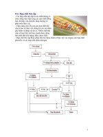
only a few years ago. Figure 6.8 is the equivalent system as implemented for the SR-2
system fielded by Cybermotion before 1998. Since only low-speed radio modems
were
available, video had to be sent over separate channels. As robots moved through
facilities, they would exceed the range of both systems.
Radio repeaters would relay the data channel to the robot, but at the expense of
bandwidth. Video, however, could not be handled by repeaters and each receiver was
connected to a switch. As the robot moved from location to location, the host
computer would send commands to the switch to select the nearest video receiver.
Actually, things were even messier than this when two-way voice communications
were required. In these situations, yet another transceiver was added to the robot.
Slave 2
(Sonar)
Slave 3
(Lidar)
Xducers
Laser
Ranger
802.11
Ethernet
Radio
Lap Top
Master Computer
Camera
Ethernet
802.11
Ethernet
Access Point
802.11
Ethernet
Access Point
Host
Computer
Ethernet
Mobile Robot
Figure 6.7. Communications structure based entirely on Ethernet
93
Communications and Control
Drivers, OCXs and DLLs
When one thinks about the incredible complexity of detail that allows video, audio,
and data to be exchanged seamlessly over an Ethernet link it would seem an impossi-
bly complicated design process. Luckily, nothing could be further from the truth
5
.
In the evolution of modern software, the issue of interfacing to a large number of
systems with different proprietary applications protocols had to be addressed. At
first, computer manufacturers tried to dictate protocol standards. These standards
specified how each feature would be controlled. However, since manufacturers were
always trying to offer more features than their competitors, attempts at standardizing
such interfaces were like trying to nail jelly to a tree.
Slave 2
(Sonar)
Slave 3
(Lidar)
Master
Mobile Base
Xducers
Laser
Ranger
Analog
Video
Tranmitter
Slave 1
Mobile Base
Radio
Modem
RS-232
RS-232
Camera
Analog
Video
Reciever
Analog
Video
Reciever
Video
Switch
Mobile Robot
Control
Supervisor
Monitor
Interface
Box
Radio
Modem
Base Station
Radio
Repeater/s
Host
Computer
RS-232
RS-232
Figure 6.8. Communications diagram of SR-2 security robot (Circa 1997)
(Courtesy of Cybermotion, Inc.)
5
When we switched our systems from analog video transmission and serial data radios to
802.11 and digital video, the process took less than two weeks.
94
Chapter 6
To allow computer operating systems to be compatible with a wide range of peripher-
als, the burden was eventually placed on the hardware vendor to provide the
interface. If the interface is at the hardware level (such as driving a printer through a
serial port), the interface program is usually called a driver. Everyone who has ever
installed a modem on their home PC has run into the process of loading the proper
driver.
When the interface is at the software level, it is usually in the form of a DLL
(dynamically linked library) or an OCX (active-X control object). A DLL is a library
containing definitions and procedures that can be called from your application. You
need to understand what each procedure does and in what sequence, and with what
data they must be called. This process is usually straightforward, but exacting.
When an interface is provided as an OCX, it is in the form of a drop-in object that
contains a completely encapsulated interface to the system. A good OCX will make
you look like a genius
6
. The software programmer manipulates the OCX by setting
its properties or calling its methods, and the OCX generates the application protocol
messages to cause the desired result. All of the communications details are hidden
from the programmer
7
. In many cases, the OCX will provide its own forms for the
control of parameters, or the display of video, and so forth.
Porting your application protocol over the Ethernet is equally simple. In Visual
Basic, you only need to drop a TCP host object into your project, and to tell it the
address of the robot. If your link is to break out on the robot to a serial (RS-232)
connection, this can be done with a small box called a port server. The port server
IP address is entered into the host along with a port number. The port number
usually defines the way the serial data will be handled. Port 6001 is typically used for
straight-through connections.
Programming the transmission and reception of data with these “drop-in” hosts and
clients is done very much as it is with serial communications. On the transmitting
end, the data is simply loaded into the transmit buffer. On the receiving end, data
arriving will generate events. These events are exactly like serial communications
interrupt handlers, and if the status properties are okay, the data can be sent to your
application protocol decoder.
6
We used a digital video system from Indigo which had an excellent OCX.
7
The proper solution to standardizing interfaces for the security robots mentioned earlier would
have been to require each robot vendor to supply an OCX with certain properties and procedures,
and not try to standardize the application layer protocol.
95
Communications and Control
Improving communications efficiency
There are many ways to improve communications efficiency. In many cases, you will
want to have more than one slave computer on a link, and there may be more than
one link in your system (as in Figure 6.5).
Broadcasts
In some cases, a host computer will want to convey the same general information to
more than one of the slaves. For example, the mobile base in Figure 6.5 may wish to
broadcast the current position and heading estimate to all the sensor systems. In this
way, slaves can process navigation information in ways not possible if they did not
know the current position data.
The simplest way to perform a broadcast is to define a special message, and to have
this message write into a special broadcast bulletin board in each of the slaves. This
bulletin board can be a reserved block of memory, or an array of data. If communica-
tions becomes particularly busy, broadcasts can be transmitted at longer intervals, as
long as they are sent reasonably often (every second or so).
The biggest problem with broadcast data such as position is that it is always out of
date,
and by varying amounts of time. In the case of position data, this can mean
that any calculation made by the slave will be wrong because of this latency.
There are two ways to minimize this latency. The first method is to provide the slave
with a predictive modeling program that runs at an interrupt rate much faster than
the update rate of the broadcast. This modeler simply updates the position estimate
in the bulletin board on the assumption that the robot is still accelerating (in each
axis) at the same rate it was when the broadcast was received. In this way, the bul-
letin board values for the robot’s position are continually updated for any task that
might need them.
T
he second method of reducing broadcast data latency requires fewer system re-
sour
ces. This method involves time-stamping incoming broadcasts against a local
time source, and provides a method or subroutine that is called in order to retrieve a
current estimate of broadcast data. When the method is called, the program simply
estimates the probable change for each axis since the data was received. This is sim-
ilar to the first method, but the data is only refreshed as actually needed.
96
Chapter 6
Flags
Flags are nothing more than variables (usually booleans, bytes, or integers) that can
take on a limited number of values, each of which has a specific assigned meaning.
Flags are a powerful tool in communications. Flags can be sent to slaves and they can
be retrieved from slaves. One of the most common uses of such flags is to place them
in a block of data that is regularly monitored by the host. The flag might tell the
host that there is some other data, somewhere in the blackboard of the slave that it
needs to look at. Flags can also request that the host perform emergency shutdown,
or any number of other actions.
Two of the most common flags are the slave computer mode and status. By checking
these integers or bytes, the host can tell if the slave is doing what it should be doing
(mode), and if it is experiencing any problems doing it (status). Error numbers are
another common example of flags.
To understand the power of flags, consider that the host computer might receive
from a
slave a simple byte representing one of 255 possible error codes. Although this code
required only a single byte to be communicated, it may result in the operator receiv-
ing a whole paragraph of explanation about the nature of the error. A word of
warning about flags is prudent at this point. If more than one of the conditions that
a flag represents can be true at the same time, a numeric flag can only represent one
of these conditions at a time. In these cases, the bits of a byte or integer can each
serve as a flag, allowing any combination to be set at the same time. The other so-
lution is to use individual flags for each condition, but this is very wasteful of band-
width as an entire integer must be read to test each condition.
Templates
Although we have already indicated that we will try to group data contiguously in a
slave’s blackboard if we expect to request it at the same time, there will always be
times when we want data from a range of different noncontiguous memory locations.
When this is the case, the overhead for requesting a few bytes here and there can be
very high.
Thus we need a template. A template is a script that the host loads into the memory
of the slave in reserved locations. The script contains a list of starting addresses and
the block size for each of these. The last of these pointers is followed by a zero-
length block that serves to terminate the template.
97
Communications and Control
The template is then requested by the host and the slave assembles the scattered
scraps of
data into a single message block. The efficiency of this messaging system is incred-
ible, and it is easily implemented.
Post offices
In complex systems such as mobile robots, communications patterns shift with the
nature of the task at hand. Furthermore, communications channels are shared re
sources
that many tasks (clients) may need to use. In the case of a base station program,
communications may be dictated by the number and type of forms that the operator
has open. It is therefore intolerably inefficient for a particular thread to wait in a
loop for the channel to become available, and then for the data to arrive.
In an efficient architecture, a task will request data before it absolutely needs it, and
while it can still do useful work before the data arrives. To do resource sharing on a
case by case basis rapidly results in unreadable code. Thus, we come to the general
concept of a resource manager.
A resource manager for a communication channel is usually called a post office. A post
office is a module (or better yet an object) that contains an array of pointers to
messages and their associated flags, and destination addresses. The elements of this
array are called post office boxes. At a minimum, a post office will have the following
methods available for the clients to use:
1. Post a request message
2. Post a send message
3. Provide status of a posted message
4. Provide status of the communications resource.
As a task needs to communicate with other systems, it calls the post office and posts
its message. The post office puts the message in the next available box, and then re-
turns a message identification code that the client can use to request the status of its
message in the future.
The reason that the post office does not simply return the box number is that boxes
are reused as time goes on. If a client does not pick up its message information before
t
he post office reuses the box, then the data in that box may have nothing to do
with the client’s request. In some schemes, the message identifier contains the box
number in its lower bits to make it easy for the post office to locate the message
when requested to do so by a client.
98
Chapter 6
For a send message, a client provides the post office with a pointer to the message da-
ta, the size of the message, the remote processor (e.g., slave) to which the data is to
be sent, and the destination address in that processor. The post office places all of this
information into the next empty box and returns the message identification number
to the client.
For a request message, a client provides the remote processor and address from which
it wants data, the number of bytes it wants. It may also pass a vector where it would
like the post office to save the received data.
When a message has been posted, the client will normally go about its business until
it reaches the point of needing to know the status of its message. To determine this,
the client calls the post office, and requests the status of the message by providing
the message identification number. The post office will typically return one of the
following status codes:
1. Unsent (Post office has not yet gotten around to the message.)
2. Pending (Message was sent but reply has not been received.)
3. Completed
4. Failed
Another useful method for a post office to provide is the status of the communica-
tions resource. This status usually indicates if the channel is connected, and the size
of the backlog of messages it has to do. In this way, some clients can opt to slow
down their requests of the channel when it becomes heavily loaded.
Advanced post offices sometimes support message priority. The priority of a message
is usually limited to two or three levels, but can be greater. A higher priority message
will get serviced sooner than a lower priority message.
Figure 6.9. Post office monitor and diagnostics display
(Courtesy of Cybermotion, Inc.)
99
Communications and Control
Message priority is handled in a simple way. The post office simply maintains a set of
post office boxes for each level of priority. When the channel becomes available, the
next message will be from the highest set of boxes that has a message posted. Thus, if
there are no messages in the level 3 boxes, the post office will check the level 2
boxes, and so forth.
Many of the field problems in robotics are communications related, so it is impor
tant to
be able to quickly determine the nature of the problem. The post office diagnostic
display in Figure 6.9 shows all of the elements just discussed for a simple single-level
post office. The bar at the bottom shows the state of all 32 of the boxes reserved for
this robot’s channel. The letter “d” indicates a message is done, while the letter “u”
indicates it is unsent, etc. Clicking the “RxMsgs” button will show the most recent
messages received that were rejected. The “Details” button gives statistics about
which messages failed.
Although the concept of a post office may seem overly complex at first glance, it is
in fact a very simple piece of code to write. The benefits far outweigh the costs.
Timing issues and error handling
Communications are seldom 100% dependable. This is particularly true if the mes-
sages must travel through more than one medium or by radio. Terrible things often
happen to our messages once they are sent out into the cruel world. It is important
that the various failure scenarios be considered in designing our communications
structure.
Flashback…
One of the funniest communications-related problems I can remember was the case of
the lazy robot. It was our first security robot and it was patrolling a relatively small,
single-story laboratory. The main route was around the outside perimeter of the office,
along an almost continuous window.
The robot would occasionally stop and refuse to accept any further orders. A security
officer would be sent over in a patrol car, and would loop around the parking lot looking
through the windows for the robot. By the time the robot was spotted, it would be
running again!
The manager of the security force assured me that he was not at all surprised because this
was exactly the way humans acted when they were given the same job! In fact, the prob-
lem was something called multipath interference.
100
Chapter 6
Multipath interference occurs when the robot is at a point where radio waves are not
being predominantly received directly from the transmitter, but rather as the result of
reflections along several paths. If one or more paths are longer than the others by one-
half wavelength, then the signals can cancel at the antenna even though the radio should
be within easy range. When the patrol car approached, it added a new reflective path and
communications was restored.
8
Data integrity
The most obvious problem in communications is data integrity. A system can be
made
tolerant of communications outages, but bad messages that get through are much
more likely to cause serious problems. There are many forms of error checking and
error correction, ranging from simple checksums to complex self-correcting proto-
cols.
It is useful to remember that if an error has a one in a million chance of going un-
detected, then a simple low-speed serial link could easily produce more than one
undetected error per day! Luckily, our application protocol is likely to be carried by
protocols that have excellent error detection. Even so, it is useful to discuss error
checking briefly.
The two most popular error checking techniques are the checksum and the CRC
(cyclical redundancy check). Checksums are calculated by merely adding or (more
commonly) subtracting the data from an accumulator, and then sending the low byte
or word of the result at the end of the data stream. The problem occurs when two
errors in a message cancel each other in the sum, leaving both errors undetected.
A CRC check is calculated by presetting a bit pattern into a shift register. An
exclusive-or is then performed between incoming data and data from logic con-
nected to taps of the shift register. The result of this exclusive-or is then fed into the
input of the shift register. The term cyclical comes from this feedback of data around
the shift register. The function may be calculated by hardware or software.
When all the data has been fed into the CRC loop, the value of the shift register is
sent as the check. Various standards use different register lengths, presets, and taps.
8
The multipath problem disappeared in data communications with the advent of spread-spectrum
radios, because these systems operate over many wavelengths. The problem is still experienced
with analog video transmission systems, causing video dropout and flashing as the robot moves.
All of these problems go away when communications is combined with video on 802.11 spread-
spectrum Ethernet systems as shown in Figure 6.5.
101
Communications and Control
It is mathematically demonstrable
9
that this form of checking is much less likely to
be subject to error canceling.
The ratio of non-data to actual data in a message protocol is called the overhead. Ge-
nerally, longer checks are more reliable, but tend to increase the overhead. Error
correcting codes take many more bytes than a simple 16-bit CRC, which in turn is
better than a checksum. The type and extent of error checking should match the
nature of the medium. There is no sense in increasing message lengths 10% to
correct errors that happen only 1% of the time. In such cases it is much easier to
retransmit the message.
Temporal integrity
A more common and less anticipated problem is that of temporal integrity. This
problem can take on many forms, but the most common is when we need data
that represents a snapshot in time. To understand how important this can become,
consider that we request the position of the robot.
First, consider the case where the X and Y position are constantly being updated by
dead reckoning as the result of interrupts from an encoder on the drive system. Ser-
vicing the interrupts from this encoder cannot be delayed without the danger of
missing interrupts, so it has been given the highest interrupt priority. This is in fact
usually the case.
Now assume the following scenario. The hexadecimal value of the X position is re-
presented by the 32-bit value consisting of two words, 0000h and FFFFh, at the
moment our position request is received. The communications program begins
sending the requested value by sending the high byte of 0000h first. At that moment
an encoder interrupt breaks in and increments the X position by one, to 0001h and
0000h. After this interruption, our communications program resumes and sends the
low word as 0000h. We receive a valid message indicating that the X position is
0000h,
0000h, an error of 32,768!
We cannot escape this problem by simply making the communications interrupt
have a higher priority than the encoder interrupt. If we do this, we may interrupt
the dead reckoning calculation while it is in a roll over or roll under condition,
resulting in the same type of error as just discussed.
9
The author makes no claim to be able to demonstrate this fact, but believes those who claim they
can!
102
Chapter 6
For this and other reasons, it is imperative that the communications task copy all of
the requested data into a buffer before beginning transmission. This transfer can take
place with interrupts disabled, or through the use of a data transfer instruction that
cannot be interrupted.
There are even more subtle forms of errors.
Flashback…
I am reminded of one of the most elusive bugs I ever experienced. The problem showed
up at very rare times, only in a few installations, always along the same paths, and in
areas with marginal radio communication. The robot would receive a new program,
begin executing it, and suddenly halt and announce an “Event of Path” error. This error
meant that the robot had been instructed to perform an action as it drove over a point
on a path, but that it did not believe the point was on the path! More rarely, the robot
would suddenly double back to the previous node and then turn back around and con-
tinue on. It was very strange behavior for a major appliance!
This bug happened so rarely that it was at first dismissed as an observer-related problem,
then as a path-programming problem. Finally, a place was found where the problem
would occur fairly regularly (one time in 100) and we continued to exercise the robot
until we were able to halt the robot at the problem and determine the cause. This is what
was happening:
When the robot finished a job, it would halt. At that point, it would be sent a new
program and then it would be told to begin execution of the program at step one. The
program was loaded in blocks, but no block would be sent until the block before it had
been successfully transmitted. Once the whole program was successfully loaded, the in-
struction pointer would be set to the first instruction and the mode would be set to
automatic. As a final check, the program itself contained a 16-bit checksum to assure
that it had been put into memory without modification.
The problem, it turned out, was caused when the robot was sent the message setting its
program pointer and mode. If this message was not confirmed within a certain time, it
was retransmitted. It had been assumed that a message timeout would be the result of this
message not being received by the robot. In that case, the code worked fine. The real
problem came when the robot did receive the message, but its reply saying that it had
received the message did not get back to the host. The host would then wait a few sec-
onds and retransmit the reply, causing the robot to jump back to the beginning of its
103
Communications and Control
program like a record jumping a track
10
. Thus, it would begin the program over even
though it might now be 50 feet from where that program was supposed to start. If it had
crossed through a node before the second message arrived, the robot would throw an
error. If it had not reached a node, then the second transmission would not cause a
problem because the program pointer was still at the first step anyway.
The result was that the problem only occurred in areas of poor communications where
the distance from the first node to the second node was relatively short. The reason it
was so hard to detect was because it occurred so rarely and because of the assumption that
the message did not go through if a reply was not received. This was a classic assumption
bug.
11
Other issues
There are other issues that arise in some situations. One of these occurs when com-
munication is routed over a network that has excessive message persistence. If the
protocol handler or post office has given up on a message due to a time-out, but one
of the networks along the way is still repeating the message, then a return message
may eventually arrive that is badly out-of-date. Worse yet, we may believe that it is
the reply to a new message, causing great confusion. For this reason, if possible, it is
best to set the message persistence of such systems to a minimum value.
Another safeguard involves tagging messages with message numbers so that it can be
determined for sure whether a reply belongs to a particular message. If a messaging
system is full duplex, then messages are being sent without waiting for replies, and
this type of tagging is essential.
Books have been written about single aspects of the issues discussed here. The im-
portant thing is to recognize the value of a good communications system, and to
anticipate as many problem scenarios as possible in structuring it. Once the structure
has been selected, you can research specific areas to the depth required. It is also
crucial not to fall into the trap of sacrificing bandwidth for development conve-
nience. It may seem that a system has more than enough bandwidth to allow such
waste, but as it grows this will almost universally prove to be untrue.
10
For the reader who is not eligible for senior discounts, I should explain that records were an
ancient means of storing and playing back music. They were plastic disks imprinted with grooves
whose bumpy sides crudely represented a series of sounds.
11
See Chapter 17.
Section 2:
Basic Navigation
Basic Navigation Philosophies
7
CHAPTER
107
Before we plunge into the subject of navigation, it is helpful to put the whole topic
into perspective. Thousands of papers have been written about robot navigation,
and many very compelling concepts have been developed. When one looks at the
actual robotic products that have been produced, however, most have used much
simpler approaches. Two schools of thought about robot navigation have emerged:
the academic school and the industrial school.
The academic school of thought
There is a recurring theme in many academic papers on robot navigation that goes
like this: “Before robots can be widely accepted, they must be capable of learning
their environments and programming themselves without assistance.” So consis-
tently is this line repeated, that one is prone to believe it must have been chiseled
on the back of the tablets that Moses brought down from the mountain. Whether it
will turn out to be a fact, however, is yet to be determined. There is evidence on
both sides of this argument.
In support of the academic argument, it is true that most potential customers (other
than the academic and hobby markets) do not want to program their robots. These
customers, quite rightly, do not want to be distracted from the primary mission focus
of their business or department. On the other hand, they do not care whether a
robot is programmed or not, as long as it is installed and does the job they expect.
The yardstick for such customers is one of return on investment (ROI). If program-
ming takes a high degree of expertise on site, then this will add to the cost of the
initial installation and certainly reduce the ROI. It is also important that the system
be readily changed when the environment changes. If changes add to operational
costs, then the ROI is reduced again.
108
Chapter 7
To those in the academic camp, the robot’s sensor systems should recognize the
entire environment, not just a feature here and there. They envision the robot as
perceiving the environment in very much the same way humans do. Indeed, this is a
wonderful goal, and some impressive progress has been made in video scene analysis.
Figure 7.1, however, shows an example of an environment that severely challenges
this goal.
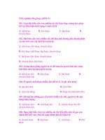
In this example, the robot is using lidar to navigate from pallets of products. The
robot patrols evenings, and is idle during the day. Thus, on successive evenings the
presence and placement of pallets may change radically. In this case, the robot has
been programmed to look only for pallets that lay near the boundary of the aisle.
The laser scans parallel to the ground at waist height. In the event that there are not
many pallets present, the robot’s programming also tells it about reflectors on a wall
to its right, and on vertical roof supports on the left (just visible at the top of the
image).
The challenge for a hypothetical self-teaching system is that almost the entire envi-
ronment changes from night to night. If such an ideal robot had a video processor
on board, and was smart enough, then it might notice that the painted stripe does
not change from night to night and learn to use it as a navigation feature. For now,
however, the safe and easy way to solve the problem is for someone to tell the robot
which features to use ahead of time.
Figure 7.1. SR-3 Security robot navigating from lidar (circa 1999)
(Courtesy of Cybermotion, Inc.)
109
Basic Navigation Philosophies
There are many ways to solve any one problem, but the trick is to create systems that
economically solve the problem reliably for multiple environments with the least expensive,
lowest power, and most reliable sensor systems possible.
The industrial school of thought
The industrial school of thought is diametrically opposed to the academic school.
This view is often verbalized as KISS (keep it simple, stupid). Many in this school
believe that if a guidance system works well by following a physical path, then why
bother with all that fancy navigation nonsense. There are, in fact, applications
where these old technologies have sufficed for decades.
People of the industrial school are business people who see themselves as providing
solutions to customer problems. They understand that the cost of development is
very high, and that the return for such investment is often insufficient. Unfortu
nately,
for those who prescribe too rigidly to this school, recent techno-history has clearly
shown that sitting still is an ever more risky survival strategy. The inherent rigidity
of physical path systems makes them potentially vulnerable to more flexible and
capable autonomous systems.
Similarly, in the case of emergency response and bomb disposal robots, there is likely
to be an evolution toward systems that make the remote operator’s job easier and the
robot safer. The simple addition of collision avoidance sensors and reflexive behav-
iors could make these robots safer and easier to drive. Such improvements would
also reduce the required operator training costs, allowing more cross training with
other jobs. There is absolutely no technical barrier to this approach, but most of the
manufacturers in this field are still producing robots with little or no automatic
capability.
In the end, the competition between these schools of thought will be settled in the
marketplace on an application-by-application basis. The result overall will most
probably be systems that are increasingly easier to install and more flexible, while
becoming less and less expensive. It is unlikely that the whole market will wait for
the perfect robot, and then burst upon it in wild enthusiasm.
Area coverage robots
Area coverage robots for applications such as lawn mowing and vacuum cleaning
have already been marketed for years with various degrees of success. These devices
110
Chapter 7
require no programming, and use a variety of strategies to cover the area they are
placed into.
At the low end, these robots have incorporated strategies that do not represent true
navigation, but rather movement patterns that should eventually cover the area. For
example, lawn-mowing robots have been developed that randomly cross an area
until they detect a boundary marker and then turn away to cross the area again.
While most of the area is covered quickly, some areas may never be covered. The
method is extremely inefficient.
The Roomba
TM
vacuuming robot produced by iRobot uses a much more effective
area-covering strategy to cover a contiguous area, and has a rudimentary sense of
position. For the job of cleaning a room in one’s home, this strategy is sufficient, and
the price is low enough that the robot does not need to be more independent to be
cost effective. The only programming required is to set the room size and possibly
install an infrared beam called a “virtual wall” to prevent a robot from moving into
undesirable areas.
Figure 7.2. Roomba
TM
area vacuum robot
(Photo courtesy of iRobot, Inc.)
111
Basic Navigation Philosophies
At the high end, cleaning robots have used sensor-based local navigation that pro-
vides efficient area coverage, but only within a contiguous and bounded area. If
these robots are not to enter a certain area, then physical barriers such as roadway
cones are used to accomplish this.
In none of these cases, however, has the robot been capable of understanding its glo-
bal position and going from one area to another to do things in a specific manner. To
do this, the robot must by very definition be programmed in some way.
Virtual path following vs. goal seeking
There are two basic philosophies about how a robot should find its way from one
place to another: virtual path following and goal seeking. Goal seeking has traditionally
been the favorite method of academia. In goal seeking the robot knows where it
wants to go in terms of coordinates and it plans the best route to achieve the goal.
In
doing so, it may or may not be provided in advance with a map of known ob
stacles. In
any case, as it encounters new obstacles it will build a map of them.
Virtual path following
Virtual path following is essentially like physical path following except that the path
is defined in the programs of the robot and not by painting a stripe on the floor. A
virtual path-following robot will typically have a path program defined either graphi-
cally or as a text program or both.
Cybermotion robots, for example, execute pseudocode programs that require the
transmission of very little data. These programs are generated using a graphical
environment called PathCAD (Figure 7.3). In the PathCAD environment, graphi-
cal objects that are dropped onto the drawing have properties that are carried
invisibly with the drawing. These objects include nodes with names such as V1, V2,
and E3 on Figure 7.3.
112
Chapter 7
Once nodes and the paths connecting them have been drawn, a graphical aid is used
to generate text “path actions.” These actions are then compiled into the path pro-
grams that the robot receives. We will discuss this process more in later sections, but
a few objects are worth noting.
Besides the nodes, objects of interest in the example shown include the event EV_31
and the range definitions RG_20, RG_62, and RG_66. Events tell a robot to do
some-
thing at a point along a path. Range lines are used in the navigation process. The
most complex object is the elevator node in the center of the drawing. This node
references all of the programs required to operate the elevator and to take the robot
from one floor to another.
Virtual paths are more than a halfway step between physical paths and goal seeking.
Since the robot knows where it is, it can also have behaviors for circumnavigation
that are very similar to goal seeking.
Goal seeking
The method of finding the shortest route through obstacles has traditionally been
based on one of several models, including “growing obstacles” and “force fields.”
Figure 7.4 demonstrates the concept of growing obstacles.
The precept is simply that the size of all obstacles is swollen by the clearance re-
quired for the robot. Once this is accomplished, one has only to assure that there is a
finite space between the swollen obstacles to plan a path between them. If the robot
Figure 7.3. PathCAD programming environment for virtual paths
(Courtesy of Cybermotion, Inc.)
113
Basic Navigation Philosophies
is oblong, then one has to decide which dimension to use to grow the obstacles. If
the width is less than the length (the usual case), then it may be tempting to use the
width as the growth dimension. If this is done, however, then the robot may not be
able to turn around in some tighter places.
Route planning by growing obstacles
The obstacle growing method is essentially binary, in that the planner tries to make
the path go as directly toward the goal as possible, and in so doing pushes the path
to the very edge of the swollen obstacles. The process yields the shortest, but not the
safest or smoothest path.
Goal
Obstacle
Obstacle
Obstacle
Start
Figure 7.4. Growing obstacles for path planning
114
Chapter 7
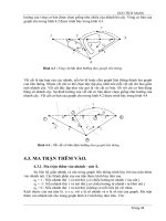
Route planning by force fields
Another popular approach is based on calculating imaginary repelling fields emanat-
ing from obstacles as shown in Figure 7.5. The fields can diminish linearly with
distance or geometrically. The process typically yields a path that stays as far away
from obstacles as possible. Limits are normally placed on the range of the field ef-
fects, so that calculations do not need to include distant objects.
In order to visualize this process, it helps to imagine the resulting map as a landscape
where the obstacles are ridges or peaks, and the most likely routes follow the valleys
(Figure 7.6). The floor of a valley occurs where two or more force fields cancel each
other and the height of a valley floor is equal to the magnitude of the canceling
fields. The path planner is allowed to route the robot through a valley as long as its
height is below a minimum. This minimum corresponds to the clearance of the
vehicle.
Goal
Obstacle
Obstacle
Obstacle
Start
Figure 7.5. Force fields for path planning
115
Basic Navigation Philosophies
Disadvantages of goal seeking
Goal seeking is elegant and interesting, but it assumes that the only reason for
choosing
a route is to avoid obstacles. In most applications, there are other reasons for choos-
ing a particular route as well. For example, a security robot’s route is planned to
assure that the robot performs surveillance on all important areas. In other cases,
there may be traffic in the area that requires rules of the road to be followed.
As mentioned earlier, the major disadvantage of goal seeking is that it takes routing
decisions out of the hands of the system programmer. Therefore, if a robot is to
patrol a
building in a specific manner using goal seeking, then it must be given a sequence of
goals that force it to cover the areas desired.
A practical starting point and “a priori” knowledge
Returning to the question of whether our robot should be self-teaching or prepro-
grammed, we must again ask the following question: “If our robot were to map its
environment without help, and be totally independent and self-programming, then
how would it know how to call and board an elevator or open a door?” Even if it
could be made smart and dexterous enough to perform these tasks, how would we
communicate what we wanted it to do?
So, which of these concepts and techniques represents the best approach? In the
end, the
most practical method of programming is one that merges many of the qualities of
both the academic and industrial camps, the virtual path-following techniques and
the goal-seeking techniques. Like so many decisions in robotics, there is a natural
answer and no matter which camp you start in you will be drawn toward the same
consensus.
Our approach will therefore be one that lies somewhere between the extremes just
discussed. Since wonderful maps and floor plans now exist in digital form for almost
every public place, we will start with these drawings as a basis for the programming
approach. The data on these maps and drawings is far more global and detailed than
our robot will ever be able to produce on its own. If we wish our robot to participate
in the mapping process, then let’s give it what we know and let it build its maps on
top of this information.
116
Chapter 7
We will then begin by telling our robot where we would like it to go, and what we
would like it to do. This is no different than what we might do for a new human
worker,
except that our means of communicating this information will be a bit different.
We will also help the robot with the selection of features it should use to navigate.
We
know which objects in its environment are permanent and which are not, so a little
help from us can greatly improve the robot’s performance. If we find a method that
allows the robot to use its sensors to add navigation features of its own, our architec-
ture should make it possible to add this capability at a later time.
Lateral Uncertainty
Obstacle
Obstacle
Robot path
Danger levels
Figure 7.6. Topological map of force fields between obstacles