COMPRESSOR HANDBOOK phần 6 potx
Bạn đang xem bản rút gọn của tài liệu. Xem và tải ngay bản đầy đủ của tài liệu tại đây (952.62 KB, 76 trang )
11.14 CHAPTER ELEVEN
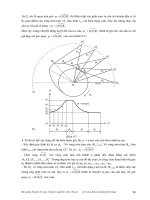
FIGURE 11.21 Typical gas flow curve for 30:1 ratio gas booster.
To find the gas flow, refer to a flow chart similar to Fig. 11.21 of the selected
booster. The gas flow depends on gas supply pressure (p
O
) and the air drive pressure
(p
A
). The flow chart above is only for 6 bar air drive. For 4 or 8 bar air drive,
another flow chart would be used.
Example: Outlet Pressure
ϭ 140 bar and Air Drive ϭ 6 bar
Gas Supply Pressure: 20 bar Gas Flow: 80 L /min
N
11.2.13 Selection of a Booster
Boosters are selected based on gas outlet pressure required, gas supply, and the air
drive pressures available. Flow capacity should be checked from a flow chart, as
the example in Fig. 11.21. If the flow capacity is not sufficient, a double acting
booster will be required. If the supply pressure is not sufficient, it would be nec-
essary to go to a two stage booster.
Example:
Air drive pressure p
A
ϭ 6 bar (88 psia)
Working pressure p
O
ϭ 140 bar (2058 psia)
GAS BOOSTERS 11.15
Gas supply pressure p
S
ϭ 15 bar (218 psia)
Gas flow required F
ϭ 40 L
N
/min (1.41 SCFM)
Using technical data, a 30:1 ratio unit is the booster that fits these conditions. Refer
to flow curve to verify flow capability.
11.2.14 Filling a Storage Tank (in a specific time)
Medium Shop Air
Air Drive Pressure (p
A
) 6 bsar (88 psi)
Supply Pressure (p
S
) 6 bar (88 psi)
Working Pressure (p
O
) 80 bar (1176 psia)
Tank Volume 20 Liter (.71 Cu Ft/Min)
Filling Time (t) 20 min
1. Pre-selected booster according to the pressure ratio
p
R
ϭ p
O
/p
A
ϭ 80/6 ϭ 13
2. Required volume in tank at 80 bar.
V
N
ϭ V ϫ p
O
ϭ 20 Liter ϫ 80 bar ϭ 1600 L
N
3. Volume in tank at supply pressure.
V
N1
ϭ V ϫ p
S
ϭ 20 Liter ϫ 6 bar ϭ 120 L
N
4. Volume to be supplied by booster.
V
N
Ϫ V
N1
ϭ F
Fill
ϭ 1600 L Ϫ 120 L ϭ 1480 L
N
11.2.15 Average Gas Flow
F
ϭ V/t ϭ 1480 L
n
/20 min ϭ 74 L
N
/min
A booster would be selected with this capacity, based on the performance curves.
12.1
CHAPTER 12
SCROLL COMPRESSORS
Robert W. Shaffer
President
Air Squared, Inc.
Initial patents for the scroll concept date back to the early 1900’s. Unfortunately
the technology to accurately make scrolls did not exist and the concept was for-
gotten. In 1972, the scroll concept was re-invented.
The potential and advantages of the scroll compressor over reciprocating com-
pressors were immediately recognized by the refrigeration industry. Because of the
tremendous pressure for better efficiency of refrigeration compressors in the early
’70s, there was a strong incentive to pursue the scroll: the balanced rotary motion
reduced noise and vibration; there were no valves to break; and valve noise and
valve losses were eliminated; fewer parts were needed; and rubbing velocities,
along with associated frictional losses were lower. Not only did the scroll com-
pressor offer improved efficiency, it also had the added benefit of greater reliability,
smoother operation and lower noise. Today, scroll compressors are used extensively
for residential and automotive air conditioning by many well known companies.
The development of scroll type compressors for air has not been as rapid. Air
is much more difficult to compress than refrigerant, especially when oil is not used
for sealing and cooling. By the ’90s, machine tool technology had progressed to
the point where scrolls could be accurately made and the first dry, oilless scroll
compressor was introduced in January, 1992. The oilless scroll air compressors had
the same inherent features as the scroll refrigeration compressor when compared
to reciprocating oilless air compressors, durability, reliability, lower noise and vi-
bration.
Currently scroll refrigerant compressors are well established as the standard of
the industry. Scroll air compressors are extending from the initial three and five
horsepower models into larger and smaller sizes from one to ten horsepower. Figure
12.1 shows typical scroll air compressors ranging in size from 1/8 to 1.0 hp.
Recently introduced technology is expected to make scroll air compressors prac-
tical in the fractional horsepower sizes.
12.2 CHAPTER TWELVE
FIGURE 12.1 Scroll air compressors from 1 / 8 to 1.0 HP.
12.1 PRINCIPAL OF OPERATION
The fundamental shape of a scroll is the involute spiral. The involute is the same
profile used in gear teeth. An involute is a curve traced by a point on a thread kept
taut as it is unwound from another curve. The curve that the thread is unwound
from, that is, used for scrolls, is a circle. The radius of the circle is the generating
radius.
A scroll is a free standing involute spiral which is bounded on one side by a
solid flat plane, or base.
A scroll set, the fundamental compressing element of a scroll compressor, vac-
uum pump or air motor, is made up of two identical involutes which form right
and left hand components. One scroll component is indexed or phased 180 degrees
with respect to the other to allow the scrolls to mesh, as shown in Fig. 12.2.
Crescent shaped gas pockets are formed bounded by the involutes and the base
plates of both scrolls. As the moving or orbiting scroll is orbited about the fixed
scroll, the pockets formed by the meshed scrolls follow the involute spiral toward
the center and diminish in size (the motion is reversed for an expander or air motor).
The orbiting scroll is prevented from rotating during this process to maintain the
180 degree phase relationship of the scrolls.
The compressor or vacuum pump’s inlet is at the periphery of the scrolls. Air
is drawn into the compressor as the inlet is formed as shown in Fig. 12.2. b, c,
and d. The entering gas is trapped in two diametrically opposed gas pockets, Fig.
SCROLL COMPRESSORS 12.3
FIGURE 12.2 Scroll compressor operation.
12.2 a, and compressed as the pockets move toward the center. The compressed
gas is exhausted through the discharge port at the center of the fixed scroll. No
valves are needed since the discharge is not in communication with the inlet. Figure
12.2 shows the scroll positions as the line connecting the centers of the two scrolls
is rotated clockwise, illustrating how gas pockets diminish in size as the orbiting
scroll is orbited.
12.2 ADVANTAGES
Scroll refrigerant compressors, air compressors and vacuum pumps have the fol-
lowing advantages:
•
Scroll compressors can achieve high pressure. The pressure ratio is increased by
adding spiral wraps to the scroll. Pressures as high as 100 to 150 psig can be
achieved in a single-stage air compressor.
•
Scroll compressors are true rotary motion and can be dynamically balanced for
smooth, vibration-free, quiet operation.
•
There are no inlet or discharge valves to break or make noise and no associated
valve losses.
•
Scroll compressors can be oil flooded, oil lubricated, or oil free.
12.4 CHAPTER TWELVE
TABLE 12.1 Typical Performance Data of Scroll Air Compressors
Nom. power
(HP)
Speed
(RPM)
Disch. press.
(PSIG)
Air flow
(ACFM)
Sound power
(dBA@ 1 m)
5.0 3050 120 15.0 59
3.0 2630 120 9.0 59
1.0 3450 100 4.0 NA
0.3 1750 30 3.0 49
0.02 3000 10 0.3 39
•
Due to the unique orbital motion, the rubbing velocities of the sliding seals are
significantly less than piston rings or vanes for comparable speeds. Rubbing ve-
locities are typically 30 to 50% less, resulting in greater durability.
•
Air is delivered continuously, therefore there is very little inlet or discharge pul-
sation and associated noise.
•
The scroll compressor has no clearance volume that gets re-expanded with as-
sociated losses. The compression is continuous.
•
Noise levels 3 to 15 dBA lower than other compressor technology are typical.
Table 12.1 gives some typical performance for scroll compressors operating on
air.
12.3 LIMITATIONS
Although scroll compressors continue to expand into larger and smaller sizes, there
are limitations. Since the scroll has a leakage path at the apex of the crescent shaped
pockets, there are limits to how small a scroll compressor can be as a function of
discharge pressure. Large displacement scroll compressors become large in diam-
eter and the moving or orbiting scroll becomes massive. The maximum centrifugal
force generated by the orbiting scroll gives a practical maximum size in a single-
stage scroll.
12.4 CONSTRUCTION
Minimizing leakage of compressed gases within the scrolls is the key to perform-
ance in a scroll compressor.
There are two primary leakage paths in a scroll compressor. There is a leakage
path at the apex of the crescent shaped air pockets where the scroll involves are
SCROLL COMPRESSORS 12.5
FIGURE 12.3 Section through involute showing tip seal.
in closest proximity. This leakage is minimized by running the scrolls with a very
small gap at these points. The size of the gap at the apex of the air pockets is a
function of scroll geometry, and the scroll geometry is a function of the scroll
manufacturing process.
There is also a leakage path between the tip of the involute and the opposite
scroll base. Since the involute is relatively long if stretched out, this path is of
primary importance. This leakage path is sealed by either, running the scrolls very
close together and using oil to seal the remaining gap or using a floating tip seal
as shown in Fig. 12.3. The floating tip seal acts much as a piston ring in a piston
type compressor and bridges the running gap between the scrolls. For oil-free
compressors, the tip seals are made of self lubricating materials.
Driven by a demand from the refrigeration industry, machine tool builders have
improved the speed and accuracy of scroll manufacture. These new machine tools
can produce finished scrolls in one to five minutes with involute accuracy of 0.0002
to 0.0005 inch and with good surface finish. Spindle speeds as high as 30,000 RPM
are typical machining scrolls made of aluminum or cast iron. Most of the major
machine tool manufacturers have standard scroll machining centers.
12.4.1 Lubricated Scroll Compressors
Typically scroll compressors used as refrigerant compressors are oil lubricated.
Lubrication greatly simplifies the compressor design. Design features include:
12.6 CHAPTER TWELVE
FIGURE 12.4 Typical scroll showing idler shafts.
•
Cast iron or aluminum scrolls with no special coatings or surface treatment re-
quired
•
A simple eccentric drive at the center of the orbiting scroll
•
A flat plate thrust bearing to support and locate the orbiting scroll axially
Since refrigerant compressor are hermetically closed systems, no special oil
clean up is needed at the discharge. The oil can simply circulate through the re-
frigeration system and return to the compressor to seal and lubricate.
SCROLL COMPRESSORS 12.7
12.4.2 Oilless Scroll Compressors
Oilless or oil-free scroll compressors are typically used for air and other gases
where the cost of oil clean up is a factor, or where zero oil can be tolerated in the
discharge. Design features include:
•
Cast iron or aluminum scrolls coated to improve corrosion and wear resistance
•
Tip seals are required for good performance and are made of a self lubricating
material.
•
Idler shafts supported by sealed rolling element bearings are used to support the
axial thrust load, locate the orbiting scroll axially and maintain the 180 degree
scroll phase relationship. See Fig. 12.4.
12.5 APPLICATIONS
Scroll compressors can primarily be used in those applications where its advantages
are of benefit, specifically low vibration and noise, and durability. Although scroll
compressors can be cost competitive, if cost is the most important factor, alternative
technology should also be considered.
Some possible applications are given below.
•
Residential air conditioning
•
Automotive air conditioning
•
Process controls
•
Pneumatic controls
•
Laboratory
•
Home health care
•
Medical and hospital
•
Computer peripherals
•
Optical equipment
Scroll compressors can be used where vane or reciprocating compressors are
used. They can be dry or oil lubricated.
13.1
CHAPTER 13
STRAIGHT LOBE COMPRESSORS
A.G. Patel, PE
Roots Divison
Divison of Dresser Industries Inc.
13.1 APPLICATIONS
Straight lobe compressors are used for pneumatic conveying of materials, aerating
liquids, extracting gases and vapors, providing low pressure air/gas, supercharging
engines and drying materials, etc.
13.1.1 Operating Characteristics
Capacity range: 5 cfm to 60,000 cfm
Pressure range: 15 psi
Vacuum range:
15 in. hgv for conventional compressor
27 in. hgv for externally aspirated compressor or liquid sealed
0.5 micron as a vacuum booster
Higher pressure and vacuum levels could be achieved through staging.
13.2 OPERATING PRINCIPLE
The more prevalent straight lobe compressors usually have rotors with two or three
lobes. The operating principal for a two-lobe compressor is described below.
In the two-lobe compressor, two figure eight rotors are mounted on parallel
shafts within an elongated cylinder. A set of timing gears keeps the rotors in syn-
chronization. In Fig. 13.1, the lower rotor is presumed to be the drive rotor. As it
rotates clockwise, the inlet is created on the right hand side and the discharge is
created on the left hand side. The driven rotor turns counter clockwise through the
action of the timing gears (not shown). In position 1, the drive rotor is delivering
volume A to the discharge, while the driven rotor is trapping the volume B between
the housing and itself. In position 2, the driven rotor has sealed off volume B from
the inlet and the discharge. Volume B is basically at inlet conditions. In position
3, volume B is being discharged by the driven rotor, while the drive rotor is in the
process of trapping volume A. The two-lobe compressor discharges four equal
13.2 CHAPTER THIRTEEN
FIGURE 13.1 Two lobe compressor pumping schematic.
volumes of the medium per one rotation of the drive shaft. There is no internal
compression of gas involved. The system resistance determines the head.
13.3 PULSATION CHARACTERISTICS
In Fig. 13.1 position 3, the trapped volume A, which is primarily at the inlet
pressure condition, is being exposed to the discharge pressure. The higher pressure
discharge medium suddenly rushes in to occupy the volume A. This sudden inrush
produces a pressure pulse.
f
ϭ 2ϫNϫK
f
ϭ pressure pulse frquency, hz
N
ϭ compressor revolution per second
K
ϭ number of lobes
In a two-lobe compressor, the pulse frequency is four times the compressor rpm.
The amplitude of the discharge pulse is controlled by controlling the rate of pres-
sure change of the trapped volume A. In their Whispair
design, Roots Operations,
a division of Dresser Industries, uses discharge gas to pre-charge the volume A in
a controlled manner to reduce pulsations.
In most of the applications, the use of a discharge pulsation dampner is mandated
to avoid pulsation damage on the equipment down stream of the compressor.
13.4 NOISE CHARACTERISTICS
The discharge pressure pulse is one of the main contributors to noise in a straight
lobe compressor. The other contributing factors are gears, bearings and flowing
gases. The impeller actions generate varying loads on the bearings. These loads
not only vary in magnitude during rotation of the impeller, they also change direc-
tion causing shock loading that the bearings transfer to the mounting structures.
STRAIGHT LOBE COMPRESSORS 13.3
FIGURE 13.2 Cross section through straight lobe compressor.
The vibrations of these structures radiate noise. For controlling noise, it is not
uncommon to enclose the straight lobe compressor in an acoustic housing.
13.5 TORQUE CHARACTERISTICS
The straight lobe compressors have a pulsating shaft torque. The torque pulsations
could be in the range of
ע 10% of the mean. Stiff couplings like gear type cou-
plings are not recommended as they would transmit the torque pulsations possibly
causing damage to the driver.
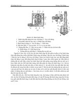
13.6 CONSTRUCTION (FIG. 13.2)
The main components of a straight lobe compressor are the rotors ➁ , the casing
➀, the timing gears ➆, the bearings ➄, and the seals ➃.
13.6.1 Rotors
The rotors (2) are nothing more than a set of two toothed gears. The common
profile for the rotor lobes is involute; cycloidal profile is also used sometimes. The
13.4 CHAPTER THIRTEEN
FIGURE 13.3 PV Diagram For Single Stage Compression
FIGURE 13.4 PV diagram for two stage compression.
shafts are either integrally cast, pressed through, or bolted stub shafts. The clear-
ances between the rotors and between the casing and the rotors is held to a mini-
mum to reduce leakage flow, the main source of compressor volumetric inefficiency.
The rotors are generally hollow; for dusty environments they are plugged to prevent
rotor imbalance.
13.6.2 Casing
The casing consists of cylinder (1) and end plates (3) also known as head plates.
The casing is normally designed for 25 psig rating.
STRAIGHT LOBE COMPRESSORS 13.5
FIGURE 13.5 Suction and discharge arrangement for straight lobe compressor.
FIGURE 13.6 5000CFM straight lobe blower driven by variable frequency driver. Installed in
a wasterwater treatment plant. (Roots Division, Dresser Industries Inc.)
13.6.3 Timing Gears
Timing gears maintain the rotor phasing without contact. Timing gears are generally
mounted on the shafts with some form of keyless interference fit to permit easy
timing of the rotors.
13.6 CHAPTER THIRTEEN
FIGURE 13.7 5000CFM straight lobe blower driven by a Waukesha engine. Installed in a was-
tewater plant. (Roots Division, Dresser Industries Inc.)
FIGURE 13.8 1760CFM, 250PSI acetylene product blower (Roots Division, Dresser In-
dustries Inc.)
STRAIGHT LOBE COMPRESSORS 13.7
13.6.4 Bearings
Antifriction bearings are generally the bearings of choice.
13.6.5 Seals
The head plate seals are generally labyrinth or piston ring. In air compressors, the
area between the headplate seals and the oil seals is vented to the atmosphere to
prevent pressure build-up in the end covers. In gas applications, the vents are closed
and mechanical face seals are used in place of oil seals. There are two types of
mechanical seals available: splash lubricated and pressure lubricated. Pressure lu-
bricated seals use oil pressure higher than the gas pressure and hence have better
gas sealing ability than the splash lubricated.
13.7 STAGING
Two main reasons for staging straight lobe compressors are for achieving higher
compression ratios, and for reducing power consumption.
13.7.1 Higher Compression Ratios
Generally, single-stage straight lobe compressors are limited to a compression ratio
of 2.0, or about 15 psi rise on air from an ambient of 14.7 psia. Above this pressure
rise, the temperature rise across the compressor becomes excessive. Higher com-
pression ratios could be achieved by staging the compressors where discharge gas
from the each stage is cooled before sending it to the next stage.
13.7.2 Reduction of Power
The straight lobe compressors do not have any internal compression. The power
required by a single-stage compressor is represented by a rectangle 1-2-4-3 on PV
diagram as shown in Fig. 13.3.
The air is drawn into the compressor at a constant inlet pressure represented by
line 1-2. The trapped volume is instantly compressed to discharge pressure as
represented by line 2-4. The air is discharged at a constant discharge pressure
represented by line 4-3. The cycle is completed by line 3-1.
By adding one more stage, power reduction represented by area 2
Ј-4Ј-4-5 in Fig.
13.4 is realized. The first stage draws in air at a constant inlet pressure. The air is
compressed to the intermediate pressure 2
Ј. Since the first stage discharge air vol-
ume has been reduced to 4
Ј, the second stage need to have a displacement of only
4
Ј. So the work required by the first stage is 1-2-2Ј-1Ј and the second stage is 1Ј-
4
Ј-4-3.
13.8 CHAPTER THIRTEEN
13.8 INSTALLATION
Figure 13.5 shows the recommended installation for a straight lobe air compressor.
The location of discharge silencer with respect to the compressor flange is very
critical. If distance ‘‘I’’ is not properly selected, there exists a possibility of setting
up resonance of discharge gas column. To avoid resonant situation,
nc
I ϽϾ
4ƒ
where
n
ϭ 1,3,5,
c
ϭ velocity of sound in ft/sec ϭ ͙kgRT
f
ϭ excitation frequency in Hz ϭ 4 ϫ rotational speed in rev/sec for two-lobe
compressor
ϭ 6 ϫ rotational speed in rev/sec for three-lobe compressor
k
ϭ specific heat ratio
g
ϭ gravity constant ϭ 32.16 ft/sec
2
R ϭ gas constant in lb.ft/ЊR
T
ϭ gas temperature in ЊRankine
For positive displacement compressors, use of relief valves is very important. Any
piping blockage could overload the compressors beyond design pressures.
14.1
CHAPTER 14
THE OIL-FLOODED ROTARY SCREW
COMPRESSOR
Hasu Gajjar
Weatherford Compression
The rotary screw compressor has attracted increased attention in the gas industry
during the last decade as an ideal compressor for low pressure/high capacity op-
erations, with low pressure defined as suction pressure at or near zero psig and
discharge pressure at less than 400 psig. Developments are underway by screw
compressor manufacturers to go to higher discharge pressures.
The rotary screw is a positive displacement compressor, like its better known
relative, the reciprocating compressor. In a comparison between the two, the rotary
screw gleans honors for its simplicity, low cost, easy maintenance and almost pul-
sation-free flow. It takes a back seat to the reciprocating compressor, however, in
handling high pressure (see Fig. 14.1.)
Benefits offered by rotary screw compressors include:
•
Simple maintenance
•
Low maintenance costs
•
Long compressor life
•
Full use of driver horsepower
•
Low operating expense
•
Low purchase price
•
High compression ratios (Rc) up to 16 Rc per stage
•
Operation at low suction pressure up to 26 inches of vacuum
•
Light weight
•
Compactness
14.1 TYPES OF COMPRESSORS (see Fig. 14.2)
Rotary compressors may be either positive displacement or dynamic compressors.
The positive displacement rotary utilizes either vanes, lobes or screws to literally
14.2 CHAPTER FOURTEEN
FIGURE 14.1 Reciprocating/rotary screw compressors.
FIGURE 14.2 Compressor types.
pack the gas into the discharge line. Dynamic compressors, on the other hand,
operate on an entirely different principle. Instead of reducing the volume of the
gas to increase its pressure, the dynamic compressor works on transfer of energy
from a rotating set of blades to a gas, and then discharges the gas into a diffuser
where the velocity is reduced and its kinetic energy is converted to static pressure.
THE OIL-FLOODED ROTARY SCREW COMPRESSOR 14.3
Reciprocating compressors consist of a piston acting within a cylinder to phys-
ically compress the gas contained within that cylinder. They may be either single-
acting or double-acting, and can be designed to accommodate practically any pres-
sure or capacity. For this reason, the reciprocating compressor is the most common
type found in the gas industry. Each compressor is designed to handle a specific
range of volumes, pressures, and compression ratios.
Compared to the rotary compressor, the reciprocating compressor is more com-
plex, and may cost more to maintain. However, its higher efficiency and ability to
handle greater pressures outweigh these disadvantages.
In the selection of a compressor unit, one of the primary considerations, besides
pressure-volume characteristics, is the type of driver. Generally, small rotary com-
pressors are driven by electric motors, while the larger rotary compressors are
usually turbine driven. Reciprocating compressors may be driven by electric mo-
tors, turbines (gas or steam) or engines (gas or diesel).
In some types of reciprocating compressors, the power cylinders and compres-
sion cylinders are integrated into one unit, and share the same frame and crankshaft.
These compressors are referred to as integral units. The power and compression
cylinders of an integral unit may be either horizontally opposed or in a V-
configuration with the power cylinders on one bank and the compression cylinders
on the other.
Another type of reciprocating compressor is the separable unit. In this type
unit, the prime mover is separate from the compressor, thereby allowing the user
to choose the driver best suited to the application. Although this design may be
slightly more complex than that of the integral unit, its inherent flexibility often
gives the separable unit an advantage over the integral unit.
A wide variety of compressor designs can be used on the separable unit includ-
ing horizontal, vertical, semi-radial and V-type. However, the most common design
is the horizontal, balanced-opposed compressor because of its stability and reduced
vibration.
14.2 HELICAL ROTORS
The rotary screw compressor consists of two intermeshing helical rotors contained
in a housing (see Fig. 14.3). Clearance between the rotor pair and between the
housing and the rotors is .003 in to .005 in. The main rotor (male rotor) is driven
through a shaft extension by an engine or electric motor. The other rotor (female
rotor) is driven by the main rotor through the oil film from the oil injection; there
is no metal contact.
The length and diameter of the rotors determine the capacity and the discharge
pressure. The longer the rotors, the higher the pressure; the larger the diameter of
the rotors, the greater the capacity.
The helical rotor grooves are filled with gas as they pass the suction port. As
the rotors turn, the grooves are closed by the housing walls, forming a compression
chamber. Lubricant is injected into the compression chamber after the grooves close
14.4 CHAPTER FOURTEEN
FIGURE 14.3 Typical rotary screw
compressor.
to provide sealing, cooling and lubrication. As the rotors turn to compress the
lubricant/gas mixture, the compression chamber volume decreases, compressing
the gas/lubricant toward the discharge port. The gas/lubricant mixture exits from
the compressor as the compression chamber passes the discharge port. Each rotor
is supported by anti-friction bearings held in end plates near the ends of the rotor
shaft. The bearings at one end, usually the discharge, fix the rotor against axial
thrust, carry radial loads, and provide for the small axial running clearances nec-
essary.
After compression, the gas/lubricant mixture enters a multi-stage separator
which removes the lubricant from the gas. From the separator, the gas flows to the
aftercooler. The lubricant is also cooled, returning to the compressor through a
thermostatically-controlled valve.
Oil is the lifeblood of a rotary screw compressor. The limited clearance inside
the rotary screw means that without proper lubrication, the screw may experience
higher than normal wear. Rotary screw compressor operators use a synthetic hy-
drocarbon oil of ISO 100, 150 or 220 viscosity. Viscosity is selected based on the
specific gravity of the gas. The gas analysis is very important in oil selection.
During the initial start-up of a unit, gas will dilute the viscosity of the oil. It
should not be allowed to drop below the minimum recommended value.
Since the rotary screw has a closed oil system, it should use minimal oil. Most
packagers design the package with oil carryover of five (5) parts per million. If a
rotary screw compressor loses oil and no leak can be found, then the oil is going
down the sell line. These conditions mean a scavenging line orifice is plugged or
a coalescing filter has collapsed.
The oil filter for the oil injected into the rotary screw is a 10-micron filter. The
fine mesh is needed to protect the bearings and shaft seal. An oil change is rec-
ommended only every 8,000 operating hours, unless the oil is contaminated. A
regular oil sampling will help the operator determine when an oil change is needed.
Many rotary screw models are available with internal capacity control and vari-
able volume ratio systems, which permit efficient variable load and pressure op-
THE OIL-FLOODED ROTARY SCREW COMPRESSOR 14.5
FIGURE 14.4a Lift valve unloading
mechanism.
FIGURE 14.4b Slide valve unloading mechanism.
eration. Such systems are particularly desirable when constant speed electric motors
are used and varying pressure conditions exist. (see Fig. 14.4a and 14.4b).
14.3 ADVANTAGES OF THE ROTARY SCREW
COMPRESSOR
In many applications, the rotary screw compressor offers significant advantages
over reciprocating compressors.
1. Its few moving parts mean the elimination of maintenance items such as com-
pressor valves, packing and piston rings, and the associated downtime for re-
placement.
14.6 CHAPTER FOURTEEN
2. The absence of reciprocating inertial forces allows the compressor to run at high
speeds, which results in more compact units.
3. The continuous flow of cooling lubricant permits much higher single-stage com-
pression ratios.
4. The compactness tends to reduce package costs.
5. Rotary screw technology reduces or eliminates pulsations, resulting in reduced
vibration.
6. Higher speeds and compression ratios help to maximize available production
horsepower.
14.4 APPLICATIONS FOR THE ROTARY SCREW
COMPRESSOR
A rotary screw compressor package is ideal for numerous compression applications,
including:
1. Fuel gas boosting
2. Casing head gas boosting
3. Vapor recovery
4. Landfill and digester gas compression
5. Propane/butane refrigeration compression
6. Compression of corrosive and/or dirty process gases
A rotary screw compressor package can also be used to upgrade existing recip-
rocating compressor installations. By boosting low suction pressure, capacity may
be increased at minimum cost with continued use of existing reciprocating equip-
ment.
If an application requires large volume/low suction pressure, but discharge pres-
sures are greater than the screw can provide, a combination screw/reciprocating
unit with a common driver can be the solution.
14.5 VAPOR RECOVERY
One example of rotary screw utilization is for vapor recovery. Vapor recovery is
the gathering of stock tank vapors and the compression of these vapors into the
gas sales line. Capturing these vapors is profitable and environmentally advisable.
The gas vapors are gathered into a common header and fed into a vapor recovery
unit (VRU), which usually includes a suction scrubber, a compressor, a driver, a
discharge cooler and separator, and controls for unattended operation. The vapors
are usually rich and wet, conditions which lead to condensate and the washout of
THE OIL-FLOODED ROTARY SCREW COMPRESSOR 14.7
lubricant. Washout causes excessive wear in vanes or piston rings. A rotary screw
compressor does not suffer from these problems for two reasons: there is enough
lubricant injected to take care of washout; and the rotary screw does not require
the rotors to make contact with the stator.
The sizing of a rotary screw compressor for vapor recovery is extremely im-
portant. An oversized unit will operate in the partial load stage or shut down and
start up too often. An undersized unit will not be able to keep up and the vents
will emit vapors into the atmosphere, defeating economy and the effort to maintain
clean air.
14.6 SIZING A ROTARY SCREW COMPRESSOR
To size a rotary screw compressor, one needs to know the suction and discharge
pressures, the desired capacity, the gas analysis, temperature and the elevation. (See
Eq. 1 for formula to determine capacity and Eq. 2 for formula to determine horse-
power.)
EQUATION 1
Rotary Screw
Compressor Capacity
ICFM
؍ D
3
(L / D)(GR)(RPM)(E
v
/C)
Rotor Diameter D
Rotor Length L
Gear Ratio GR
Driver Speed RPM
Volumetric Efficiency E
v
Rotor Profile C
EQUATION 2
Rotary Screw
Compressor Power
K
Ϫ
1/K
K(P/P) Ϫ 1
21
W ؍ PQ؋؋ ؉WL
R1
K Ϫ 1E
a
Pressures P , P
12
Gas Flow Rates Q
Gas Properties K
Adiabatic Efficiencies E
a
Mechanical Losses W
L
Figures 14.5A and 14.5B show adiabatic efficiency at different pressure ratios,
while Fig. 14.6 shows efficiency change with variable volume ratio.
14.8 CHAPTER FOURTEEN
FIGURE 14.5a Adiabatic efficiency (pressure ratio to
7).
FIGURE 14.5b Adiabatic efficiency (pressure ratio to 15).