Gear Geometry and Applied Theory Episode 2 Part 9 pps
Bạn đang xem bản rút gọn của tài liệu. Xem và tải ngay bản đầy đủ của tài liệu tại đây (752.71 KB, 30 trang )
P1: JXR
CB672-18 CB672/Litvin CB672/Litvin-v2.cls February 27, 2004 1:5
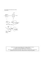
18.7 Pointing of Face-Gear Teeth Generated by Involute Shaper 523
Figure 18.7.2: Cross section profiles of
face-gear and shaper in plane
2
.
2
is designated by “A” (Fig. 18.7.2). Point A has to be located on the addendum
line of the face-gear, and therefore its location with respect to axis y
a
is determined by
r
ps
− 1/P
d
(Fig. 18.7.2). The goal is determination of magnitude L
2
defined by distance
l between planes
1
and
2
(Fig. 18.6.2). Figures 18.6.2 and 18.7.2 illustrate the
procedure of derivation of magnitude
l
and L
2
. The computation of L
2
is based on
the following procedure:
Step 1: Determination of pressure angle α of pointed teeth (Fig. 18.7.2).
We use vector equation (Fig. 18.7.2)
O
∗
a
N + NM + MA = O
∗
a
A. (18.7.1)
(See the location of point O
∗
a
in Fig. 18.6.2.) Here,
O
∗
a
A = r
ps
−
1
P
d
=
N
s
− 2
2P
d
(18.7.2)
where P
d
is the diametral pitch; point M is the point of tangency of profiles of the shaper
and the face-gear in plane
2
(Fig. 18.7.2); |MA|=λ
s
; |NM|=r
bs
θ
s
.
Vector equation (18.7.1) yields two scalar equations in two unknowns α and λ
s
:
r
bs
(cos α + θ
s
sin α) − λ
s
cos α =
N
s
− 2
2P
d
(18.7.3)
r
bs
(sin α − θ
s
cos α) − λ
s
sin α = 0. (18.7.4)
Here, r
bs
= (N
s
/(2P
d
)) cos α
0
; θ
s
= α − θ
0s
; θ
0s
= π/(2N
s
) − inv α
0
. Eliminating λ
s
,we
obtain the following equation for determination of α:
α − sinα
N
s
− 2
N
s
cos α
0
=
π
2N
s
− inv α
0
. (18.7.5)
The sought-for angle α is obtained by solving the nonlinear equation (18.7.5).
P1: JXR
CB672-18 CB672/Litvin CB672/Litvin-v2.cls February 27, 2004 1:5
524 Face-Gear Drives
Step 2: Determination of magnitude L
2
(Fig. 18.6.2).
Figure 18.7.2 yields
O
∗
a
I =
r
bs
cos α
=
N
s
cos α
0
2P
d
cos α
. (18.7.6)
Then, we obtain (Fig. 18.6.2)
L
2
=
O
∗
a
I
tan γ
s
=
N
s
cos α
0
2P
d
cos α tanγ
s
. (18.7.7)
Knowing the magnitudes of L
1
and L
2
(Fig. 18.6.2), it becomes possible to design a
face-gear of the gear drive that is free of undercutting and pointing.
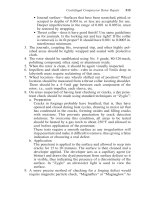
18.8 FILLET SURFACE
Two types of fillet surfaces might be provided: (i) those generated by the generatrix G
of the addendum cylinder [Fig. 18.4.3(a)], and (ii) those generated by the rounded top
of the shaper (Fig. 18.8.1).
Case 1: Generation of the fillet by edge G [Fig. 18.4.3(a)].
Using Fig. 18.5.1, we represent edge G [Fig. 18.4.3(a)] in coordinate system S
s
by
vector function r
s
(u
s
,θ
∗
s
) where
θ
∗
s
=
r
2
as
−r
2
bs
0.5
r
bs
, r
as
= r
ps
+
1.25
P
d
=
N
s
+ 2.5
2P
d
. (18.8.1)
The fillet surface is represented in S
2
by the equation
r
2
(u
s
,ψ
s
) = M
2s
(ψ
s
)r
s
(u
s
,θ
∗
s
). (18.8.2)
Case 2: Generation of the fillet by the rounded top of the shaper.
The fillet is generated as the envelope to the family of circles of radius ρ (Fig. 18.8.1).
The investigation of bending stresses shows that application of a shaper with a rounded
top reduces bending stresses on approximately 10% with respect to those obtained by
application of an edged top shaper.
Figure 18.8.1: Rounded top of the shaper tooth.
P1: JXR
CB672-18 CB672/Litvin CB672/Litvin-v2.cls February 27, 2004 1:5
18.9 Geometry of Parabolic Rack-Cutters 525
Figure 18.9.1: Illustration of rack-cutter profiles; (b) and
(c) parabolic profiles of the shaper and pinion rack-cutters,
respectively.
18.9 GEOMETRY OF PARABOLIC RACK-CUTTERS
Basic Concept
The second version of the geometry of face-gear drives is based on the following ideas
Litvin et al. [2002b]:
(i) Two imaginary rigidly connected rack-cutters designated as A
1
and A
s
are applied
for generation of the pinion and the shaper, respectively. Designation A
0
indicates
a reference rack-cutter with straight-line profiles (Fig. 18.9.1).
(ii) Rack-cutters A
1
and A
s
are provided with mismatched parabolic profiles that de-
viate from the straight-line profiles of reference rack-cutter A
0
. Figure 18.9.1(a)
shows schematically an exaggerated deviation of A
1
and A
s
from A
0
. The parabolic
profiles of rack-cutters A
1
and A
s
for one tooth side are shown schematically in
Figs. 18.9.1(b) and 18.9.1(c).
(iii) The tooth surfaces
1
and
s
of the pinion and the shaper are determined as
envelopes to the tooth surfaces of rack-cutters A
1
and A
s
, respectively.
(iv) The tooth surfaces of the face-gear
2
are generated by the shaper and are de-
termined by a sequence of two enveloping processes wherein (a) the parabolic
rack-cutter A
s
generates the shaper, and (b) the shaper generates the face-gear. The
face-gear tooth surface
2
may also be ground (or cut) by a worm (hob) of a special
shape (see Section 18.14).
(v) The pinion and face-gear tooth surfaces are in point contact at every instant because:
(i) rack-cutters A
1
and A
s
are mismatched [Fig. 18.9.1(a)] due to application of two
P1: JXR
CB672-18 CB672/Litvin CB672/Litvin-v2.cls February 27, 2004 1:5
526 Face-Gear Drives
different parabola coefficients, and (ii) the pinion and the shaper are provided with
a different number of teeth. Figures 18.9.1(b) and 18.9.1(c) show schematically the
profiles of the rack-cutters of the pinion and the shaper, respectively. Application
of both items, (i) and (ii), provides more freedom for observation of the desired
dimensions of the instantaneous contact ellipse and for the predesign of a parabolic
function of transmission errors.
(vi) An alternative method of generation of face-gears is based on application of a worm
of a special shape, which might be applied for grinding or cutting (Fig. 18.1.3).
Grinding enables us to harden the tooth surfaces and to increase the permissible
contact stresses. It is shown below that the derivation of the worm thread surface
is based on simultaneous meshing of the shaper with the face-gear and the worm
(see Section 18.14).
Reference and Parabolic Rack-Cutters
Reference rack-cutter A
0
has straight-line profiles [Fig. 18.9.1(a)]. Parabolic rack-cutters
designated as A
s
and A
1
are in mesh with the shaper and the pinion. Parabolic profiles
of A
s
and A
1
deviate from straight-line profiles of A
0
.
Coordinate systems S
q
and S
r
are applied for derivation of equations of shaper rack-
cutter A
s
. Parameters u
r
and parabola coefficient a
r
determine the parabolic profile of
rack-cutter A
s
[Fig. 18.9.1(b)]. Respectively, coordinate systems S
k
and S
e
are applied
for derivation of equations of rack-cutter A
1
. Parameters u
e
and parabola coefficient a
e
determine the parabolic profile of rack-cutter A
1
[Fig. 18.9.1(c)]. Origins O
q
and O
k
of coordinate systems S
q
and S
k
, respectively [Figs. 18.9.1(b) and 18.9.1(c)], coincide,
and their location is determined by parameter f
d
. The profiles of the rack-cutter are
considered for the side with profile angle α
d
[Fig. 18.9.1(a)].
The design parameters of reference rack-cutter A
0
[Fig. 18.9.1(a)] are w
0
, s
0
, and α
d
.
Taking into account that
w
0
+ s
0
= p =
π
P
(18.9.1)
we obtain
s
0
=
p
1 +λ
=
π
(1 +λ)P
; w
0
=
λp
1 +λ
=
λπ
(1 +λ)P
. (18.9.2)
Here, λ = w
0
/s
0
, and p and P are the circular and diametral pitches, respectively.
The tooth surface of rack-cutter A
s
is represented in coordinate system S
r
[Fig.
18.9.1(a)] as
r
r
(u
r
,θ
r
) =
(u
r
− f
d
) sin α
d
−l
d
cos α
d
− a
r
u
2
r
cos α
d
(u
r
− f
d
) cos α
d
+l
d
sin α
d
+ a
r
u
2
r
sin α
d
θ
r
1
. (18.9.3)
P1: JXR
CB672-18 CB672/Litvin CB672/Litvin-v2.cls February 27, 2004 1:5
18.10 Derivation of Tooth Surfaces of Shaper and Pinion 527
Parameter θ
r
is measured along the z
r
axis. Parameter l
d
is shown in Fig. 18.9.1(a).
Normal N
r
to the shaper rack-cutter is represented as
N
r
(u
r
) =
cos α
d
+ 2a
r
u
r
sin α
d
−sin α
d
+ 2a
r
u
r
cos α
d
0
. (18.9.4)
Similarly, we may represent vector function r
e
(u
e
,θ
e
) of pinion rack-cutter A
1
and
normal N
e
(u
e
).
18.10 SECOND VERSION OF GEOMETRY: DERIVATION OF TOOTH
SURFACES OF SHAPER AND PINION
Shaper Tooth Surface
We apply for derivation of shaper tooth surface
s
: (i) movable coordinate sys-
tems S
r
and S
s
that are rigidly connected to the shaper rack-cutter and the shaper,
and (ii) fixed coordinate system S
n
[Fig. 18.10.1(a)]. Rack-cutter A
s
and the shaper
perform related motions of translation and rotation determined by (r
ps
ψ
r
) and ψ
r
[Fig. 18.10.1 (a)].
Figure 18.10.1: For generation of shaper of
pinion by rack-cutters: (a) generation of the
shaper, (b) installation of pinion rack-cutter,
and (c) generation of the pinion.
P1: JXR
CB672-18 CB672/Litvin CB672/Litvin-v2.cls February 27, 2004 1:5
528 Face-Gear Drives
The shaper tooth surface
s
is determined as the envelope to the family of rack-cutter
surfaces A
s
considering simultaneously the following equations:
r
s
(
u
r
,θ
r
,ψ
r
)
= M
sr
(ψ
r
)r
r
(u
r
,θ
r
) (18.10.1)
N
r
(u
r
) ·v
(sb)
r
= f
sr
(
u
r
,ψ
r
)
= 0. (18.10.2)
Here, vector function r
s
(
u
r
,θ
r
,ψ
r
)
represents in S
s
the family of rack-cutter A
s
tooth
surfaces; matrix M
sr
(ψ
r
) describes coordinate transformation from S
r
to S
s
; vector
function N
r
(u
r
) represents the normal to the rack-cutter A
s
[see Eq. (18.9.4)]; v
(sb)
r
is
the relative (sliding) velocity.
Equation (18.10.2) (the equation of meshing) yields
f
sr
(u
r
,ψ
r
) =
x
r
N
yr
− y
r
N
xr
r
ps
N
yr
− ψ
r
= 0. (18.10.3)
Finally, we represent the surface of the shaper by vector function
r
s
(u
r
(ψ
r
),ψ
r
,θ
r
) = R
s
(ψ
r
,θ
r
). (18.10.4)
The normal to the shaper is represented in coordinate system S
s
as
N
s
=
∂R
s
∂ψ
r
×
∂R
s
∂θ
r
. (18.10.5)
Pinion Tooth Surface
Movable coordinate systems S
e
and S
1
are rigidly connected to the pinion rack-cutter
and the pinion, respectively [Figs. 18.10.1(b) and 18.10.1(c)]; S
∗
n
is the fixed coordinate
system. The installation angle β [Fig. 18.10.1(b)] is provided for the improvement of
the bearing contact between the pinion and the face-gear (see Section 18.13). Derivations
of pinion tooth surfaces are similar to those applied for derivation of shaper tooth
surfaces and are based on the following procedure:
Step 1: We obtain the family of pinion rack-cutters represented in coordinate system
S
1
as
r
1
(
u
e
,θ
e
,ψ
e
)
= M
1e
(ψ
e
)r
e
(u
e
,θ
e
) (18.10.6)
where matrix M
1e
describes coordinate transformation from S
e
via S
∗
n
to S
1
[Figs.
18.10.1(b) and 18.10.1(c)].
Step 2: Using the equation of meshing between the rack-cutter and the shaper, we
obtain
u
e
(ψ
e
) =
x
e
N
ye
− y
e
N
xe
r
p1
N
ye
− ψ
e
. (18.10.7)
Step 3: We represent the pinion tooth surfaces by vector function
r
1
(u
e
(ψ
e
),ψ
e
,θ
e
) = R
1
(ψ
e
,θ
e
). (18.10.8)
P1: JXR
CB672-18 CB672/Litvin CB672/Litvin-v2.cls February 27, 2004 1:5
18.11 Derivation of Face-Gear Tooth Surface 529
18.11 SECOND VERSION OF GEOMETRY: DERIVATION
OF FACE-GEAR TOOTH SURFACE
Preliminary Considerations
The face-gear tooth surface is determined as the result of two enveloping processes
wherein (i) a parabolic rack-cutter generates the shaper tooth surface (see Section 18.10),
and (ii) the shaper generates the face-gear tooth surface. The second enveloping process
is based on the algorithm presented in Section 18.5 wherein an involute shaper generates
the face-gear tooth surface of the first version of geometry. Recall that the shaper tooth
surface of the second version of geometry is represented in two-parameter form by vector
function R
s
(ψ
r
,θ
r
) [see Eq. (18.10.4)]. The normal to the surface mentioned above is
represented by vector function (18.10.5). Investigation of undercutting of surface
2
(of the second version of geometry) is based on the algorithm discussed in Section 18.6.
Structure of Face-Gear Tooth Surface Σ
2
The type of a surface may be defined by the Gaussian curvature that represents the
product of principal surface curvatures at the chosen surface point. Thus, the Gaussian
curvature K at a surface point M is defined as
K = K
I
K
II
(18.11.1)
where K
I
and K
II
are the principal surface curvatures at M. The type of surface point
(elliptical, parabolic, or hyperbolic) depends on the sign of Gaussian curvature K.
Direct determination of Gaussian curvature for a surface represented by three,
sometimes four, related parameters requires complex derivations and computations.
The derivations and computations previously mentioned may be simplified using pro-
posed relations between the curvatures of the generating and generated surfaces (see
Chapter 8).
Investigation shows that surface
2
has elliptical (K > 0) and hyperbolic (K < 0)
points (Fig. 18.11.1). The common line of both sub-areas is the line of parabolic points.
The dimensions of the area of surface elliptical points depend on the magnitude of
the parabola coefficient a
r
of the shaper rack-cutter. Surface
2
of the first version of
geometry contains only hyperbolic points.
18.12 DESIGN RECOMMENDATIONS
The bending stresses in a face-gear drive depend on the unitless coefficient
c = P
d
l = P
d
(L
2
− L
1
). (18.12.1)
(See the designations of L
2
and L
1
in Fig. 18.6.2.) Usually, the coefficient c is chosen as
c = 10 for high-power transmissions. The coefficient c can be increased for face-gear
drives by choosing a higher gear ratio and increasing the tooth number. This statement
can be confirmed by the graphs shown in Fig. 18.12.1 for face-gear drives of the first
type of geometry.
P1: JXR
CB672-18 CB672/Litvin CB672/Litvin-v2.cls February 27, 2004 1:5
530 Face-Gear Drives
Figure 18.11.1: Areas of elliptical and hyperbolic points of face-gear tooth surface
2
for rack-cutter
parabola coefficients (a) a
r
= 0.01 1/mm, (b) a
r
= 0.02 1/mm, and (c) a
r
= 0.03 1/mm.
The investigation of the influence of coefficient c on the structure of the face-gear
teeth is based on the following considerations: Assume that the outer radius L
2
is known
(it has been determined from the conditions of avoidance of pointing). We are able to
eliminate the portion of the tooth where the fillet exists (Figs. 18.6.2 and 18.11.1) by
increasing the inner radius L
1
. This means that the coefficient c will be decreased [see
Figure 18.12.1: Graphs of coefficient c for
face-gears of the first type of geometry.
P1: JXR
CB672-18 CB672/Litvin CB672/Litvin-v2.cls February 27, 2004 1:5
18.13 Tooth Contact Analysis (TCA) 531
Figure 18.12.2: Illustration of influence of parabola coefficient a
r
and gear ratio m
2s
on coefficient c.
Eq. (18.12.1)]. However, observing a sufficient value of c enables us to obtain a more
uniform structure, eliminating the weaker part of the face-gear tooth.
Figure 18.12.2 shows the influence of the parabola coefficient a
r
of the parabolic
profile of the rack-cutter and the gear ratio on the possible tooth length of the face-gear
of the second type of geometry. Results of the investigation of undercutting and pointing
are shown in Fig. 18.12.2, which represents the influence of gear ratio m
2s
and parabola
coefficient a
r
on the coefficient c represented in Eq. (18.12.1).
18.13 TOOTH CONTACT ANALYSIS (TCA)
Tooth contact analysis is directed at simulation of meshing and contact of surfaces
1
and
2
and enables investigation of the influence of errors of alignment on transmission
errors and the shift of bearing contact. The algorithm for simulation of meshing is
based on equations that describe the continuous tangency of surfaces
1
and
2
and is
presented in Section 9.4.
Applied Coordinate Systems
The following coordinate systems are applied for TCA: (a) coordinate system S
f
, rigidly
connected to the frame of the face-gear drive [Fig. 18.13.1(a)]; (b) coordinate sys-
tems S
1
[Fig. 18.13.1(a)] and S
2
[Fig. 18.13.2(b)], rigidly connected to the pinion and
the face-gear respectively; and (c) auxiliary coordinate systems S
d
, S
e
, and S
q
, ap-
plied for simulation of errors of alignment of the face-gear drive [Figs. 18.13.2(a) and
18.13.2(b)].
All misalignments are referred to the gear. Parameters E, B, and B cot γ determine
the location of origin O
q
with respect to O
f
[Fig. 18.13.1(b)]. Here, E is the shortest
distance between the pinion and the face-gear axes when the axes are crossed but not
intersected. The location and orientation of coordinate systems S
d
and S
e
with respect
to S
q
are shown in Fig. 18.13.2(a). The misaligned face-gear performs rotation about
the z
e
axis [Fig. 18.13.2(b)].
P1: JXR
CB672-18 CB672/Litvin CB672/Litvin-v2.cls February 27, 2004 1:5
532 Face-Gear Drives
Figure 18.13.1: Coordinate systems applied for simu-
lation of meshing, I.
Figure 18.13.2: Coordinate systems ap-
plied for simulation of meshing, II.
P1: JXR
CB672-18 CB672/Litvin CB672/Litvin-v2.cls February 27, 2004 1:5
18.13 Tooth Contact Analysis (TCA) 533
Computational Procedure
The algorithm of TCA is based on simulation of continuous tangency of surfaces
1
and
2
accomplished as follows (see Section 9.4):
(1) Surfaces
1
and
2
and their unit normals are represented in the fixed coordinate
system S
f
by vector functions
r
(i )
f
(
u
i
,θ
i
,φ
i
)(
i = 1, 2
)
(18.13.1)
n
(i )
f
(
u
i
,θ
i
,φ
i
)(
i = 1, 2
)
. (18.13.2)
(2) Continuous tangency of
1
and
2
is represented by vector equations
r
(1)
f
(
u
1
,θ
1
,φ
1
)
− r
(2)
f
(
u
2
,θ
2
,φ
2
)
= 0 (18.13.3)
n
(1)
f
(
u
1
,θ
1
,φ
1
)
− n
(2)
f
(
u
2
,θ
2
,φ
2
)
= 0. (18.13.4)
Here,
(
u
i
,θ
i
)
(i = 1, 2) are the surface parameters of
1
and
2
, φ
1
and φ
2
are
the angles of rotation of the pinion and the face-gear in the process of meshing.
Vector equations (18.13.3) and (18.13.4) yield a system of five independent scalar
equations (because
n
(1)
f
=
n
(2)
f
= 1) represented in terms of six unknowns as
f
i
(u
1
,θ
1
,φ
1
, u
2
,θ
2
,φ
2
) = 0, f
i
∈ C
1
(
i = 1, ,5
)
. (18.13.5)
(3) Surfaces
1
and
2
are in point contact at every instant and one of the parameters,
say φ
1
, may be chosen as the input one. The requirement of point contact yields
the inequality
∂
(
f
1
, f
2
, f
3
, f
4
, f
5
)
∂
(
u
1
,θ
1
, u
2
,θ
2
,φ
2
)
= 0. (18.13.6)
Then the solution of system of equations (18.13.5) may be represented by functions
{
u
1
(
φ
1
)
,θ
1
(
φ
1
)
, u
2
(
φ
1
)
,θ
2
(φ
1
),φ
2
(
φ
1
)
}
∈ C
1
. (18.13.7)
The solution of system of equations (18.13.3) and (18.13.4) by functions (18.13.7)
is an iterative process and requires as a first guess the set of parameters
P
(0)
u
(0)
1
,θ
(0)
1
,φ
(0)
1
, u
(0)
2
,θ
(0)
2
,φ
(0)
2
(18.13.8)
that satisfies system of equations (18.13.3) and (18.13.4).
(4) The solution by functions (18.13.7) enables us to obtain:
(a) transmission function φ
2
(φ
1
) and function of transmission errors
φ
2
(φ
1
) = φ
2
(φ
1
) −
N
1
N
2
φ
1
; (18.13.9)
P1: JXR
CB672-18 CB672/Litvin CB672/Litvin-v2.cls February 27, 2004 1:5
534 Face-Gear Drives
(b) the paths of contact on surfaces
1
and
2
that are represented, respectively,
as
r
1
(u
1
(φ
1
),θ
1
(φ
1
)) (18.13.10)
r
2
(u
2
(φ
1
),θ
2
(φ
1
)). (18.13.11)
Results of Investigation
The results of investigation of the first version of geometry are represented in Fig.
18.13.3 which shows the shift of the bearing contact due to errors of alignment. It has
been found that the bearing contact of the face-gear drive is oriented across the tooth
surface and is sensitive to the change γ of the shaft angle. Such an orientation of the
bearing contact may cause an edge contact wherein the formation of the bearing contact
is considered (in addition to stress analysis).
The sensitivity of face-gear drives of the first version of geometry to the change γ
of the shaft angle may be compensated by the axial correction q of the face-gear in
the process of assembly [Fig. 18.13.3(c)]. The advantage of the first version of geometry
is that the transmission errors of the gear drive are equal to zero. This is the result of
application of an involute shaper for generation that has equidistant profiles.
The results of TCA of the second version of geometry are represented in Figs. 18.13.4
and 18.13.5. The main advantages of the mentioned type of geometry are as follows:
(i) Longitudinal orientation of bearing contact that enables us to avoid the edge
contact.
(ii) Reduction of stresses (see Section 18.15).
The sensitivity of the gear drive of the second type of geometry to error γ may be
compensated as well by correction q.
For face-gear drives of the second type of geometry, the misalignment of the gear
drive is accompanied with transmission errors. However, application of a predesigned
parabolic function of transmission errors provides a favorable shape of the function
of errors of the drive and reduces the magnitude of maximal transmission errors (see
Figure 18.13.3: Path of contact, bearing
contact, and major axis of contact ellipses
for the following examples: (a) no errors
of alignment, (b)
|
γ
|
= 3 arcmin, and (c)
adjustment of path of contact by applying
the axial displacement q of the face-gear
with respect to the pinion (
|
γ
|
= 3 arcmin,
|
q
|
= 550 µm).
P1: JXR
CB672-18 CB672/Litvin CB672/Litvin-v2.cls February 27, 2004 1:5
18.14 Application of Generating Worm 535
Figure 18.13.4: Path of contact, bearing contact, and major axis of contact ellipses for the following
examples: (a) no errors of alignment, (b)
|
γ
|
= 2 arcmin, and (c) adjustment of path of contact by
application of correction q:
|
γ
|
= 2 arcmin,
|
q
|
= 350 µm.
Section 9.2). The predesigned parabolic function of transmission errors is obtained by
(i) mismatch of parabolic rack-cutters for the shaper and the pinion of the gear drive,
and (ii) application of a shaper with tooth number N
s
> N
p
, where N
p
is the tooth
number of the pinion of the gear drive.
18.14 APPLIC ATION OF GENERATING WORM
Concept of Generating Worm
The conventional method for generation of a face-gear is based on (i) application of an
involute shaper, and (ii) manufacturing of the face-gear performed as the simulation of
meshing of the shaper and the face-gear being generated.
Figure 18.13.5: Parabolic function of transmission errors for proposed geometry.
P1: JXR
CB672-18 CB672/Litvin CB672/Litvin-v2.cls February 27, 2004 1:5
536 Face-Gear Drives
Figure 18.14.1: Illustration of simultaneous meshing of shaper, worm, and face-gear.
Edward W. Miller proposed in 1942 the generation of the face-gear by a hob [Miller,
1942]. The next step was done by the patent proposed by Litvin et al. [Litvin et al.,
2000a] that has formulated the exact determination of the thread surface of a generating
worm that provides the necessary conditions of conjugation of the tooth surfaces of the
hob, the shaper, and the face-gear; the concept of worm design; and avoidance of worm
singularities. The worm design as proposed above may be applied for grinding and
cutting of face-gears [Litvin et al., 2002a].
Designations
s
,
w
, and
2
indicate surfaces of the shaper, worm, and face-gear,
respectively. Simultaneous meshing of
s
,
w
, and
2
is illustrated by Fig. 18.14.1.
Shaper surface
s
is considered as the envelope to the family of rack-cutter A
s
surfaces
and is represented by vector function R
s
(ψ
r
,θ
r
) [see Eq. (18.10.4)]. Surfaces
w
and
2
are generated as the envelopes to the family of shaper surfaces
s
.
Recall that with the second type of geometry, the shaper is provided with non-involute
profiles (see Section 18.10). We discuss in this section application of the worm for
generation of a face-gear of the second type of geometry. However, the discussed idea
may be applied as well for the generation of face-gears of the first type of geometry.
Crossing Angle Between Axes of Shaper and Worm
Figure 18.14.2 shows fixed coordinate systems S
a
, S
b
, and S
c
applied for illustration
of installation of the worm with respect to the shaper. Movable coordinate systems S
s
and S
w
are rigidly connected to the shaper and the worm. Axis z
s
(it coincides with z
a
)
is the axis of rotation of the shaper. Axis z
w
(it coincides with z
c
) is the axis of rotation
of the worm. Axes z
s
and z
w
are crossed and form a crossing angle of 90
o
± λ
w
. The
upper (and lower) sign corresponds to application of a right-hand (left-hand) worm.
The shortest distance between axes z
s
and z
w
is designated as E
ws
.
The crossing angle λ
w
is
λ
w
= arcsin
r
ps
N
s
(E
ws
+r
ps
)
. (18.14.1)
P1: JXR
CB672-18 CB672/Litvin CB672/Litvin-v2.cls February 27, 2004 1:5
18.14 Application of Generating Worm 537
Figure 18.14.2: Coordinate systems S
s
, S
w
, and worm installation.
Here, r
ps
is the pitch radius of the shaper, and E
ws
(Fig. 18.14.2) is the shortest distance
between the axes of the shaper and the worm. The magnitude of E
ws
affects the dimen-
sions of the grinding worm and the conditions of avoidance of surface singularities of
the worm (see below).
Determination of Worm Surface Σ
w
The worm surface
w
is determined in coordinate system S
w
(Fig. 18.14.2) by the
following equations:
r
w
(ψ
r
,θ
r
,ψ
w
) = M
ws
(ψ
w
)R
s
(ψ
r
,θ
r
) (18.14.2)
∂R
s
∂ψ
r
×
∂R
s
∂θ
r
· v
(sw)
s
= f
ws
(ψ
r
,θ
r
,ψ
w
) = 0. (18.14.3)
Here, relative velocity v
(sw)
s
is determined by differentiation and transformation of ma-
trix M
ws
that are similar to derivations in Section 2.2; vector function r
w
(ψ
r
,θ
r
,ψ
w
)is
the family of shaper surfaces
s
represented in S
w
; matrix M
ws
(ψ
w
) describes coordinate
transformation from S
s
to S
w
; Eq. (18.14.3) is the equation of meshing between
s
and
w
. Parameters (ψ
r
,θ
r
) in vector function R
s
(ψ
r
,θ
r
) represent the surface parameters
of the shaper; parameter ψ
w
is the generalized parameter of motion in the process of
generation of the worm by the shaper. Recall that during generation of the worm, the
shaper and the worm perform rotations about crossed axes z
a
and z
w
(Fig. 18.14.2).
P1: JXR
CB672-18 CB672/Litvin CB672/Litvin-v2.cls February 27, 2004 1:5
538 Face-Gear Drives
Angles of rotation ψ
ws
and ψ
w
(Fig. 18.14.2) are related by the equation
ψ
ws
ψ
w
=
1
N
s
(18.14.4)
where N
s
is the number of teeth of the shaper. It is assumed that a single-thread worm
is applied.
Equations (18.14.2) and (18.14.3) represent the worm surface
w
by three related
parameters. We may represent
w
in two-parameter form using the following procedure:
(i) We apply the theorem of implicit function system existence and consider that one
of the derivatives of f
ws
, say ∂ f
ws
/∂θ
r
, is not equal to zero.
(ii) Then, we can solve equation f
ws
= 0 by function θ
r
(ψ
r
,ψ
w
) ∈ C
1
and represent
the worm surface
w
by
r
w
(ψ
r
,θ
r
(ψ
r
,ψ
w
),ψ
w
) = R
w
(ψ
r
,ψ
w
). (18.14.5)
Conceptual Consideration of Simultaneous Meshing
of Surfaces Σ
S
, Σ
w
, and Σ
2
The shaper surface
s
is in line contact with the worm surface
w
and the face-gear tooth
surface
2
. This type of surface contact is obtained because
w
and
2
are generated
as envelopes to shaper surface
s
. We designate by L
ws
the lines of tangency between
s
and
w
and by L
2s
the lines of tangency between
s
and
2
. Investigation of lines
L
ws
and L
2s
shows that they do not coincide with each other but are intersected at any
position of meshing.
Generation of Surface Σ
2
by Worm Surface Σ
w
We recall that the shaper surface
s
is in line contact with worm surface
w
and with
face-gear tooth surface
2
. However, surfaces
w
and
2
are in point contact with
each other at any instant. This means that finishing grinding of
2
by worm surface
w
cannot be accomplished as a one-parameter enveloping process. A grinding process
based on one-parameter enveloping of the worm and the face-gear will provide only a
strip on required surface
2
. Therefore, generation of
2
by the worm has to be based
on a two-parameter enveloping process wherein two independent sets of parameters
are provided as: (i) a set of angles of rotation (ψ
w
,ψ
2
) of the worm and the face-gear,
and (ii) a translational motion l
w
of the worm. Parameters ψ
w
and ψ
2
are the angles of
rotation of the worm and the face-gear related by the equation
ψ
w
ψ
2
=
N
2
N
w
(18.14.6)
where N
2
and N
w
are the number of teeth of the face-gear and the number of threads
of the worm. Usually, a single-thread worm is applied and N
w
= 1. Parameter l
w
of
translational motion is provided as collinear to the axis of the shaper (see below).
Surface
2
generated by the grinding worm as a two-parameter enveloping process
coincides with surface
2
generated by the shaper.
P1: JXR
CB672-18 CB672/Litvin CB672/Litvin-v2.cls February 27, 2004 1:5
18.14 Application of Generating Worm 539
Figure 18.14.3: Contact lines between the shaper and the worm in the plane of surface parameters
(u
s
,θ
s
) for (a) the first type of geometry, and (b) the second type of geometry.
The approach for determination of worm singularities is the same as that applied
for determination of singularities of face-gear tooth surface
2
(Section 18.6). Figures
18.14.3(a) and 18.14.3(b) show, in the space of surface parameters, lines of tangency
of the shaper with the worm that are determined for the existing and proposed design,
respectively. Lines Q are the image of singular points on the plane of surface parameters
of the shaper. Figure 18.14.3 enables us to determine the maximal angle of rotation of
the shaper permissible for avoidance of worm singularities. Then it becomes possible to
determine the maximal number of turns of the thread of the worm.
Figure 18.14.4(a) shows lines A
(1)
and A
(2)
on the shaper tooth surface formed by
regular points of the shaper. Points of lines A
(1)
and A
(2)
generate singular points on the
worm surface. The worm surface
w
must be limited with two lines B to avoid under-
cutting of the worm.
Dressing of the Worm
The worm dressing is based on generation of its surface
w
point by point by a plane
or by a conical disk that has the same profile as the rack-cutter that generated the
shaper. The execution of motions of the disk or the plane with respect to the worm is
accomplished by application of a CNC machine. The determination of instantaneous
P1: JXR
CB672-18 CB672/Litvin CB672/Litvin-v2.cls February 27, 2004 1:5
540 Face-Gear Drives
Figure 18.14.4: Illustration of worm singularities: (a) regular points A of shaper that generate worm
singularities; (b) singularities B on worm thread surface.
installments of the grinding disk with respect to the worm requires application of a
computer program.
The computational procedure is as follows:
Step 1: Consider vector function r
w
(ψ
r
,ψ
r
(θ
r
,ψ
w
),ψ
w
) [see Eq. (18.14.4)] and take
ψ
r
= const.
Step 2: Assign θ
r
and obtain ψ
w
from ψ
w
= ψ
w
(ψ
r
,θ
r
).
Step 3: Compute x
w
, y
w
, z
w
from r
w
(ψ
r
,θ
r
,ψ
w
(ψ
r
,θ
r
)) = R
w
(ψ
r
,θ
r
).
Step 4: Knowing ψ
r
, it is easy to get the unit normal to the shaper determined as
n
s
(ψ
r
) and then determine the unit normal to the worm surface determined as
n
w
(ψ
r
,ψ
w
) = L
ws
(ψ
w
)n
s
(ψ
r
). (18.14.7)
Step 5: The data (x
w
, y
w
, z
w
, n
w
) are sufficient for the installation of the tool (a plane
or a disk) using a CNC machine.
The second type of geometry allows application of a worm with a larger number of
turns of the thread.
P1: JXR
CB672-18 CB672/Litvin CB672/Litvin-v2.cls February 27, 2004 1:5
18.15 Stress Analysis 541
18.15 STRESS ANALYSIS
The goals of stress analysis presented in this section are:
(i) Comparison of contact and bending stresses of two types of geometry of face-gear
drives
(ii) Comparison of bending stresses of two versions of face-gears generated with edged
and rounded top shapers, respectively (Fig. 18.8.1)
(iii) Determination of contact and bending stresses and investigation of formation of
the bearing contact during the cycle of meshing.
The performed stress analysis is based on the finite element method [Zienkiewicz &
Taylor, 2000] and application of a general purpose computer program [Hibbit, Karlsson
& Siresen, Inc., 1998]. The authors’ approach to application of finite element analysis
is based on the following ideas:
(a) The generation of finite element models is performed automatically by using the
equations of the tooth surfaces and taking into account the corresponding fillets
and portion of the rim. Loss of accuracy due to the development of solid models
by using CAD computer programs is avoided.
(b) The proposed approach does not require an assumption of load distribution in
the contact area. The contact algorithm of the general purpose computer program
[Hibbit, Karlsson & Siresen, Inc., 1998] is used to get the contact area and stresses
by application of torque to the pinion. The face-gear is considered at rest.
(c) Finite element models are developed numerically at the chosen contact point of the
path of contact. Stress convergence is assured because there is at least one point of
contact between the contacting surfaces.
(d) Finite element models of three pairs of teeth are applied and therefore the boundary
conditions are far enough from the loaded areas of the teeth.
Numerical Example
Finite element analysis has been performed for two types of geometry of face-gear drives
represented in Tables 18.15.1 and 18.15.2. For the second type of geometry of face-gear
Table 18.15.1: Design parameters of face-gear
of first type of geometry
Number of teeth of the pinion N
1
= 25
Number of teeth of the shaper N
s
= 28
Number of teeth of the face-gear N
2
= 160
Module m = 6.35 mm
Driving-side pressure angle α
d
= 25.0
o
Coast-side pressure angle α
c
= 25.0
o
Shaft angle γ
m
= 90.0
o
Inner radius of the face-gear 471.0 mm
Outer radius of the face-gear 559.0 mm
P1: JXR
CB672-18 CB672/Litvin CB672/Litvin-v2.cls February 27, 2004 1:5
542 Face-Gear Drives
Table 18.15.2: Design parameters of face-gear of second type
of geometry
Number of teeth of the pinion N
1
= 25
Number of teeth of the shaper N
s
= 28
Number of teeth of the face-gear N
2
= 160
Module m = 6.35 mm
Driving-side pressure angle α
d
= 25.0
o
Coast-side pressure angle α
c
= 25.0
o
Shaft angle γ
m
= 90.0
o
Inner radius of the face-gear 493.0 mm
Outer radius of the face-gear 567.0 mm
Rack-cutter dimensional coefficient λ
t
= 0.90
Parabola coefficient of rack-cutter A
s
a
s
= 7.50 · 10
−3
1/mm
Parabola coefficient of rack-cutter A
1
a
1
= 3.00 · 10
−3
1/mm
Driving-side offset parabola f
d
= 2.00 mm
Coast-side offset parabola f
c
= 0.00 mm
Pinion helix angle β = 0.05
o
drives, the application of a rounded top shaper (Fig. 18.8.1) has also been considered
in order to compare the bending stresses at the fillet of the generated face-gear.
The finite element mesh of three pairs of teeth of the second type of geometry is
represented in Fig. 18.15.1. Continuum solid elements of first order, enhanced by in-
compatible nodes to improve their bending behavior, have been used to form the finite
element mesh. The total number of elements is 44,820 with 58,327 nodes. The material
is steel with the properties of Young’s Modulus E = 2.068 ×10
8
mN/mm
2
and Poisson’s
1
2
3
Pinion
Face-Gear
Figure 18.15.1: Three-pairs-of-teeth face-gear drive finite element model.
P1: JXR
CB672-18 CB672/Litvin CB672/Litvin-v2.cls February 27, 2004 1:5
18.15 Stress Analysis 543
(Ave. Crit.: 75%)
S, Mises
+8.056e+00
+4.546e+04
+9.092e+04
+1.364e+05
+1.818e+05
+2.273e+05
+2.727e+05
+3.182e+05
+3.636e+05
+4.091e+05
+4.545e+05
+5.000e+05
+1.453e+06
1
2
3
Bending Stresses: 80000 mN/mm2
Edge Contact
Figure 18.15.2: Contact and bending stresses for the first type of geometry of face-gear drive.
Figure 18.15.3: Contact and bending stresses for the second type of geometry of face-gear drive gen-
erated with an edged-top shaper.
P1: JXR
CB672-18 CB672/Litvin CB672/Litvin-v2.cls February 27, 2004 1:5
544 Face-Gear Drives
(Ave. Crit.: 75%)
S, Mises
+2.484e+00
+4.364e+04
+8.727e+04
+1.309e+05
+1.745e+05
+2.182e+05
+2.618e+05
+3.055e+05
+3.491e+05
+3.927e+05
+4.364e+05
+4.800e+05
+7.515e+05
1
2
3
Bending Stresses: 118000 mN/mm2
Figure 18.15.4: Contact and bending stresses for the second type of geometry of face-gear drive gen-
erated with a rounded-top shaper.
ratio of 0.29. A torque of 1600 Nm has been applied to the pinion for both versions of
face-gear drive.
Figures 18.15.2 and 18.15.3 show the maximum contact and bending stresses ob-
tained at the mean contact point for the first and second type of geometry, respectively.
For such examples, a traditional edged-top shaper has been applied. Comparison be-
tween Figs. 18.15.1 and 18.15.2 shows that:
(i) Edge contact can be avoided, reducing the magnitude of the maximum contact
stress up to 40%.
(ii) For a considerable part of the cycle of meshing only one pair of teeth is in contact.
The maximum bending stress at the fillet of the first type of geometry of face-gear
is 43% lower.
Figure 18.15.4 confirms that application of a rounded-top shaper (Fig. 18.8.1) reduces
the bending stresses of the face-gear from 6 to 12% during the cycle of meshing. This
enables us to keep the increment of the bending stresses for the second type of geometry
to less than 40%.
The performed stress analysis has been complemented with investigation of formation
of the bearing contact (Figs. 18.15.2 to 18.15.5). Figures 18.15.5 and 18.15.6 illustrate
the variation of bending and contact stresses of the gear and the pinion during the cycle
of meshing for the second type of geometry, an application of an edged-top shaper and
P1: JXR
CB672-18 CB672/Litvin CB672/Litvin-v2.cls February 27, 2004 1:5
18.15 Stress Analysis 545
Figure 18.15.5: Variation of functions of contact and bending stresses during the cycle of meshing for
(a) the face-gear, and (b) the pinion of the second type of geometry and an edged-top shaper.
a rounded-top shaper, respectively. The stresses are represented as functions of unitless
parameter φ represented as
φ =
φ
P
− φ
in
φ
fin
− φ
in
, 0 ≤ φ ≤ 1. (18.15.1)
Here, φ
P
is the pinion rotation angle; φ
in
and φ
fin
are the magnitudes of the pinion
angular positions in the beginning and at the end of the cycle of meshing.
P1: JXR
CB672-18 CB672/Litvin CB672/Litvin-v2.cls February 27, 2004 1:5
546 Face-Gear Drives
Figure 18.15.6: Variation of functions of contact and bending stresses during the cycle of meshing for
(a) the face-gear, and (b) the pinion of the second type of geometry and a rounded-top shaper.
The unitless stress coefficient σ (Figs. 18.15.5 and 18.15.6) is defined as
σ =
σ
P
σ
P
max
, |σ |≤1. (18.15.2)
Here, σ
P
is the variable of function of stresses, and σ
P
max
is the magnitude of maximal
stress.
P1: JsY
CB672-19 CB672/Litvin CB672/Litvin-v2.cls February 27, 2004 1:28
19 Worm-Gear Drives with Cylindrical Worms
19.1 INTRODUCTION
There are two types of worm-gear drives: (i) those with cylindrical worms (Fig. 19.1.1)
(single-enveloping worm-gear drives), and (ii) those with hourglass worms (see Chap-
ter 20) (double-enveloping worm-gear drives). The terms “single-enveloping” and
“double-enveloping” are confusing because in both cases the surface of the worm-
gear tooth is the envelope to the one-parameter family of worm thread surfaces that
are generated in the coordinate system rigidly connected to the worm-gear. The thread
surface of a cylindrical worm is a helicoid. (We recall that a helicoid is the surface that
is generated by a given curve while it performs a screw motion.)
This chapter covers (i) the generation and geometry of cylindrical worms, and (ii) the
basic design problems (relations between design parameters). Depending on the method
for generation, we differentiate henceforth the following types of cylindrical worms (see
German Standards DIN 3975):
(i) ZA worms, with surface A. The worm surface is a ruled surface that is generated
by a straight line while it performs a screw motion with respect to the worm axis.
The generating line intersects the worm axis and therefore the axial section of the
worm surface is a straight line that is just the generating line. The cross section of
the ZA worm is an Archimedes spiral (see Section 19.4).
(ii) ZN worms, with surface N. The worm surface is also a ruled surface. However, the
generating line lies in a plane that passes through the perpendicular to the worm
axis and forms angle λ
p
with the worm axis (see Section 19.5). Here, λ
p
is the
lead angle on the pitch cylinder on the worm. The cross section of the worm is an
extended involute (see Section 19.5).
(iii) ZI worms, with surface I. The worm surface is a screw involute surface that may be
considered a particular case of a ruled surface. Such a surface can be generated by
a straight line that performs a screw motion about the worm axis and is tangent to
the helix on the base cylinder of the worm. The cross section of the worm surface
is an involute curve. The ZI worm is identical to an involute helical gear whose
tooth number is the number of worm threads.
(iv) ZK worms, with surface K. The worm surface is not a ruled surface but an envelope
to the family of cone surfaces. Such a family of surfaces is generated by the surface
547