Gear Geometry and Applied Theory Episode 2 Part 8 pps
Bạn đang xem bản rút gọn của tài liệu. Xem và tải ngay bản đầy đủ của tài liệu tại đây (742.56 KB, 30 trang )
P1: JXR
CB672-17 CB672/Litvin CB672/Litvin-v2.cls February 27, 2004 0:58
17.7 Generation of Double-Crowned Pinion by a Worm 493
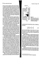
Figure 17.7.3: For illustration of axodes of worm, pinion, and rack-cutter.
the rack-cutter corresponds to rotation of the pinion with angular velocity ω
(p)
. The
relation between v
1
and ω
(p)
is defined as
v
1
= ω
(p)
r
p
(17.7.3)
where r
p
is the radius of the pinion pitch cylinder.
Step 3: An additional motion of surface
c
with velocity v
aux
along direction t−t of
skew rack-cutter teeth (Fig. 17.7.3) is performed and this motion does not affect the
generation of surface
σ
. Vector equation v
2
= v
1
+ v
aux
allows us to obtain velocity
v
2
of rack-cutter
c
in a direction that is perpendicular to the axis of the worm. Then,
we may represent the generation of worm surface
w
by rack-cutter
c
considering
that the rack-cutter performs translational motion v
2
while the worm is rotated with
angular velocity ω
(w)
. The relation between v
2
and ω
(w)
is defined as
v
2
= ω
(w)
r
w
(17.7.4)
where r
w
is the radius of the worm pitch cylinder.
P1: JXR
CB672-17 CB672/Litvin CB672/Litvin-v2.cls February 27, 2004 0:58
494 New Version of Novikov–Wildhaber Helical Gears
Figure 17.7.4: Contact lines L
cσ
and L
cw
corresponding to meshing of rack-cutter
c
with pinion and
worm surfaces
σ
and
w
, respectively.
Worm surface
w
is generated as the envelope to the family of rack-cutter surfaces
c
.
Step 4: The discussion above enables us to verify simultaneous generation of profile-
crowned pinion tooth surface
σ
and worm thread surface
w
by rack-cutter surface
c
. Each of the two generated surfaces
σ
and
w
are in line contact with rack-cutter
surface
c
. However, the contact lines L
cσ
and L
cw
do not coincide but rather intersect
each other as shown in Fig. 17.7.4. Here, L
cσ
and L
cw
represent the lines of contact
between
c
and
σ
, and between
c
and
w
, respectively. Lines L
cσ
and L
cw
are
obtained for a chosen value of related parameters of motion between
c
,
σ
, and
w
.
Point N of intersection of lines L
cw
and L
cσ
(Fig. 17.7.4) is the common point of
tangency of surfaces
c
,
σ
, and
w
.
Profile Crowning of Pinion
Profile-crowned pinion tooth surface
σ
has been previously obtained by using rack-
cutter surface
c
. Direct derivation of generation of
σ
by the worm
w
may be ac-
complished as follows:
(a) Consider that worm surface
w
and pinion tooth surface
σ
perform rotation
between their crossed axes with angular velocities ω
(w)
and ω
(p)
. It follows from
previous discussions that
w
and
σ
are in point contact and N is one of the
instantaneous points of contact of
w
and
σ
(Fig. 17.7.4).
(b) The concept of direct derivation of
σ
by
w
is based on the two-parameter
enveloping process (see Section 6.10). The process of such enveloping is based
on application of two independent sets of parameters of motion [Litvin & Seol,
1996]:
(i) One set of parameters relates the angles of rotation of the worm and the pinion
as
m
wp
=
ω
(w)
ω
(p)
= N
p
(17.7.5)
where the number N
w
of worm threads is considered as N
w
= 1, and N
p
is
the number of teeth of the pinion.
(ii) The second set of parameters of motion is provided as a combination of two
components: (1) translational motion s
w
of the worm that is performed
P1: JXR
CB672-17 CB672/Litvin CB672/Litvin-v2.cls February 27, 2004 0:58
17.7 Generation of Double-Crowned Pinion by a Worm 495
Figure 17.7.5: Schematic of generation: (a) without worm plunging; (b) with worm plunging.
collinear to the axis of the pinion [Fig. 17.7.5(a)], and (2) small rotational
motion of the pinion about the pinion axis determined as
ψ
p
=
s
w
p
(17.7.6)
where p is the screw parameter of the pinion.
Analytical determination of a surface generated as the envelope to a two-parameter
enveloping process is presented in Section 6.10.
The schematic generation of
σ
by
w
is shown in Fig. 17.7.5(a) wherein the shortest
center distance is shown as an extended one for the purpose of better illustration. In the
process of meshing of
w
and
σ
, the worm surface
w
and the profile-crowned pinion
surface perform rotation about crossed axes. The shortest distance is executed as
E
wp
= r
p
+r
w
. (17.7.7)
Surfaces
w
and
σ
are in point tangency. Feed motion of the worm is provided as a
screw motion with the screw parameter of the pinion. Designations in Fig. 17.7.5(a)
indicate (1) M
1
and M
2
are points on pitch cylinders (these points do not coincide with
each other because the shortest distance is illustrated as extended); (2) ω
(w)
and ω
(p)
are
the angular velocities of the worm and profile-crowned pinion in their rotation about
P1: JXR
CB672-17 CB672/Litvin CB672/Litvin-v2.cls February 27, 2004 0:58
496 New Version of Novikov–Wildhaber Helical Gears
crossed axes; (3) s
w
and ψ
p
are the components of the screw motion of the feed
motion; and (4) r
w
and r
p
are the radii of pitch cylinders.
Double Crowning of Pinion
We have presented above the generation by a worm of a profile-crowned surface
σ
of
the pinion. However, our final goal is the generation by a worm of a double-crowned
surface
1
of the pinion. Two approaches are proposed for this purpose:
WORM PLUNGING. Additional pinion crowning (longitudinal crowning) is provided
by plunging of the worm with respect to the pinion which is shown schematically in
Fig. 17.7.5(b). Plunging of the worm in the process of pinion generation is performed as
variation of the shortest distance between the axes of the grinding worm and the pinion.
The instantaneous shortest center distance E
wp
(s
w
) between the grinding worm and
the pinion is executed as [Fig. 17.7.5(b)]:
E
wp
(s
w
) = E
(0)
wp
− a
pl
(s
w
)
2
. (17.7.8)
Here, s
w
is measured along the pinion axis from the middle of the pinion; a
pl
is
the parabola coefficient of the function a
pl
(s
w
)
2
; and E
(0)
wp
is the nominal value of
the shortest distance defined by Eq. (17.7.7). Plunging of the worm with observation of
Eq. (17.7.8) provides a parabolic function of transmission errors in the process of mesh-
ing of the pinion and the gear of the proposed new version of the Novikov–Wildhaber
helical gear drive.
MODIFIED ROLL OF FEED MOTION. Conventionally, the feed motion of the worm is pro-
vided by observation of relation (17.7.6) between components s
w
and ψ
p
. For the
purpose of pinion longitudinal crowning, the following function ψ
p
(s
w
) is observed:
ψ
p
(s
w
) =
s
w
p
+ a
mr
(s
w
)
2
(17.7.9)
where a
mr
is the parabola coefficient of the parabolic function in Eq. (17.7.9). Modified
roll motion is provided to the worm instead of worm plunging. Application of func-
tion ψ
p
(s
w
) enables us to modify the pinion tooth surface and provide a parabolic
function of transmission errors of the proposed gear drive.
The derivation of double-crowned surface
1
of the pinion by application of both
previously mentioned approaches is based on determination of
1
as a two-parameter
enveloping process:
Step 1: We consider that surface
w
is determined as the envelope to the rack-cutter
surface
c
. The determination of
w
is a one-parameter enveloping process.
Step 2: Double-crowned surface
1
of the pinion is determined as an envelope of a
two-parameter enveloping process by application of the following equations:
r
1
(u
w
,θ
w
,ψ
w
, s
w
) = M
1w
(ψ
w
, s
w
)r
w
(u
w
,θ
w
) (17.7.10)
N
w
· v
(w1,ψ
w
)
w
= 0 (17.7.11)
N
w
· v
(w1,s
w
)
w
= 0. (17.7.12)
P1: JXR
CB672-17 CB672/Litvin CB672/Litvin-v2.cls February 27, 2004 0:58
17.8 TCA of a Gear Drive with a Double-Crowned Pinion 497
Here, (u
w
,θ
w
) are the worm surface parameters, and (ψ
w
, s
w
) are the generalized pa-
rameters of motion of the two-parameter enveloping process. Vector equation (17.7.10)
represents the family of surfaces
w
of the worm in coordinate system S
1
of the pin-
ion. Equations (17.7.11) and (17.7.12) represent two equations of meshing. Vector N
w
is the normal to the worm tooth surface
w
and is represented in system S
w
. Vector
v
(w1,ψ
w
)
w
represents the relative velocity between the worm and pinion determined un-
der the condition that parameter ψ
w
of motion is varied and the other parameter s
w
is held at rest. Vector v
(w1,s
w
)
w
is determined under the condition that parameter s
w
is
varied and the other parameter of motion ψ
w
is held at rest. Both vectors of relative
velocity are represented in coordinate system S
w
. Vector equations (17.7.10), (17.7.11),
and (17.7.12) (considered simultaneously) determine a double-crowned pinion tooth
surface obtained by a two-parameter enveloping process (see Section 6.10).
17.8 TC A OF A GEAR DRIVE WITH A DOUBLE-CROWNED PINION
Simulation of meshing of a gear drive with a double-crowned pinion is investigated
by application of the same algorithm discussed in Section 17.5 for a gear drive with a
profile-crowned pinion and gear tooth surfaces. The TCA has been performed for the
following cases:
(1) The new version of the Novikov–Wildhaber helical gear drive.
(2) The modified involute helical gear drive, whose design is based on the following
ideas: (i) a pinion rack-cutter with a parabolic profile and a conventional gear rack-
cutter with a straight profile are applied for the generation of the pinion and the
gear, respectively; and (ii) the pinion of the gear drive is double-crowned.
The applied design parameters are shown in Table 17.8.1 for both the new version
of the Novikov–Wildhaber gear drive (case 1) and the modified involute helical gear
Table 17.8.1: Design parameters
Number of teeth of the pinion, N
1
17
Number of teeth of the gear, N
2
77
Module, m 5.08 mm
Driving-side pressure angle, α
d
25
◦
Coast-side pressure angle, α
c
25
◦
Helix angle, β 20
◦
Parameter of rack-cutter, b 0.7
Face width 90 mm
Radius of the worm pitch cylinder, r
w
98 mm
Parabolic coefficient of pinion rack-cutter
(a)
, a
c
0.016739 mm
−1
Parabolic coefficient of gear rack-cutter
(a)
, a
t
0.0155 mm
−1
Parabolic coefficient of plunging
(a)
, a
pl
0.00005 mm
−1
Parabolic coefficient of pinion rack-cutter
(b)
, a
c
0.016739 mm
−1
Parabolic coefficient of gear rack-cutter
(b)
, a
t
0.0mm
−1
Parabolic coefficient of plunging
(b)
, a
pl
0.0000315 mm
−1
(a)
Novikov–Wildhaber helical gear drive.
(b)
Modified involute helical gear drive.
P1: JXR
CB672-17 CB672/Litvin CB672/Litvin-v2.cls February 27, 2004 0:58
498 New Version of Novikov–Wildhaber Helical Gears
(arc sec)
(rad)
φ
φ
Figure 17.8.1: Output of TCA for a gear drive wherein the pinion is generated by plunging of the
grinding worm: (a) path of contact and (c) function of transmission errors for the new version of the
Novikov–Wildhaber helical gear drive; (b) path of contact for the modified involute helical gear drive.
drive (case 2). The same parabolic coefficient of profile crowning for the pinion rack-
cutter a
c
has been used for both the new version of the Novikov–Wildhaber gear drive
and the modified involute helical gear drive. The parabolic coefficient of longitudinal
crowning a
pl
used in each case provides a limited error of 8 arcsec of the predesigned
function of transmission errors for a gear drive without errors of alignment. Figures
17.8.1(a) and 17.8.1(b) show the path of contact for cases (1) and (2), respectively.
Figure 17.8.1(c) shows the function of transmission errors for case (1). The function of
transmission errors for case (2) is similar and also provides a maximum transmission
error of 8 arcsec. The TCA output shows that a parabolic function of transmission
errors is indeed obtained in the meshing of the pinion and the gear due to application
of a double-crowned pinion.
The approaches chosen for TCA cover application of (i) a disk-shaped tool (Sec-
tion 17.6), (ii) a plunging worm (Section 17.7), and (iii) modified roll of feed motion
P1: JXR
CB672-17 CB672/Litvin CB672/Litvin-v2.cls February 27, 2004 0:58
17.8 TCA of a Gear Drive with a Double-Crowned Pinion 499
Figure 17.8.2: Influence of errors of alignment in the shift of the path of contact for a Novikov–
Wildhaber helical gear drive wherein the pinion is generated by plunging of the generating worm:
(a) with error E [70 µm]; (b) with error γ [3 arcmin]; (c) with error λ [3 arcmin]; (d) with
γ + λ
1
= 0 arcmin.
(Section 17.7). These approaches yield almost the same output of TCA. The simulation
of meshing is performed for the following errors of alignment: (i) change of center
distance E = 70 µm, (ii) change of shaft angle γ = 3 arcmin, (iii) error λ = 3
arcmin, and (iv) combination of errors γ and λ as γ + λ = 0.
The results of TCA accomplished for the design parameters represented in
Table 17.8.1 are as follows:
(1) Figures 17.8.1(a) and 17.8.1(b) show that the paths of contact of aligned gear
drives are oriented longitudinally in both cases of design Novikov–Wildhaber
gears and modified helical gears. Deviation from the longitudinal direction is less
for modified involute helical gear drives in comparison with the new version of
the Novikov–Wildhaber helical gear drive. However, the advantage of the new
Novikov–Wildhaber gear drive is the reduction of stresses (see Section 17.10).
(2) Figures 17.8.2(a), 17.8.2(b), and 17.8.2(c) show the shift of the paths of contact
caused by errors of alignment E, γ , and λ, respectively. The shift of paths of
contact caused by γ may be compensated by correction λ
1
of the pinion (or λ
2
of the gear). Figure 17.8.2(d) shows that the location of the path of contact can be
restored by correction of λ
1
of the pinion by taking γ + λ
1
= 0. This means
that correction of λ
1
can be used for the restoration of the location of the path
of contact. Correction of λ
1
or λ
2
may be applied in the process of generation
of the pinion or the gear, respectively.
P1: JXR
CB672-17 CB672/Litvin CB672/Litvin-v2.cls February 27, 2004 0:58
500 New Version of Novikov–Wildhaber Helical Gears
It was previously mentioned (see Section 17.5) that double crowning of the pinion
provides a predesigned parabolic function of transmission errors. Therefore, linear func-
tions of transmission errors caused by γ , λ, and other errors are absorbed by the
predesigned parabolic function of transmission errors φ
2
(φ
1
). The final function of
transmission errors φ
2
(φ
1
) remains a parabolic one. However, increase of the magni-
tude of errors γ and λ may result in the final function of transmission errors φ
2
(φ
1
)
becoming a discontinued one. In such a case, the predesigned parabolic function φ
2
(φ
1
)
has to be of larger magnitude or it becomes necessary to limit the range of γ , λ, and
other errors.
17.9 UNDERCUTTING AND POINTING
The pinion of the drive is more sensitive to undercutting than the gear because the pinion
has a smaller number of teeth.
Undercutting
Avoidance of undercutting is applied to pinion tooth surface
σ
and is based on the
following ideas:
(i) The appearance of singular points on generated surface
σ
is the warning that the
surface may be undercut in the process of generation [Litvin, 1989].
(ii) Singular points on surface
σ
are generated by regular points on the generating
surface
c
when the velocity of a contact point in its motion over
σ
becomes
equal to zero [Litvin, 1989; Litvin, 1994]:
v
(σ )
r
= v
(c)
r
+ v
(cσ)
= 0. (17.9.1)
(iii) Equation (17.9.1) and differented equation of meshing
d
dt
[ f (u
c
,θ
c
,ψ
σ
)] = 0 (17.9.2)
allow us to determine a function
F (u
c
,θ
c
,ψ
σ
) = 0 (17.9.3)
that relates parameters u
c
,θ
c
, and ψ
σ
at a point of singularity of surface
σ
.
The limitation of generating surface
c
for avoidance of singularities of generated
surface
σ
is based on the following procedure:
(1) Using equation of meshing f
σ c
(u
c
,θ
c
,ψ
σ
) = 0 between the rack-cutter and the
pinion, we may obtain in plane of parameters (u
c
,θ
c
) the family of contact lines of
the rack-cutter and the pinion. Each contact line is determined for a fixed parameter
of motion ψ
σ
.
(2) The sought-for limiting line L [Fig. 17.9.1(a)] that limits the rack-cutter surface
is determined in the space of parameters (u
c
,θ
c
) by simultaneous consideration
of equations f
σ c
= 0 and F = 0 [Fig. 17.9.1(a)]. Then we can obtain the limiting
P1: JXR
CB672-17 CB672/Litvin CB672/Litvin-v2.cls February 27, 2004 0:58
17.9 Undercutting and Pointing 501
(mm)
θ
(mm)
Figure 17.9.1: Contact lines L
σ c
and limiting line L: (a) in plane (u
c
, θ
c
), and (b) on surface
c
.
line L on the surface of the rack-cutter [Fig. 17.9.1(b)]. The limiting line L on the
rack-cutter surface is formed by regular points of the rack-cutter, but these points
will generate singular points on the pinion tooth surface.
Limitations of the rack-cutter surface by L enables us to avoid singular points on the
pinion tooth surface. Singular points on the pinion tooth surface can be obtained by
coordinate transformation of line L on rack-cutter surface
c
to surface
σ
.
Pointing
Pointing of the pinion means that the width of the topland becomes equal to zero.
Figure 17.9.2(a) shows cross sections of the pinion and the pinion rack-cutter. Point
A
c
of the rack-cutter generates the point A
σ
that is the limiting point of the cross
section of the pinion tooth surface which is still free of singularities. Point B
c
of the
rack-cutter generates point B
σ
of the pinion profile. Parameter s
a
indicates the chosen
width of the pinion topland. Parameter α
t
indicates the pressure angle at point Q.
Parameters h
1
and h
2
indicate the limitation of location of limiting points A
c
and B
c
of the rack-cutter profiles. Figure 17.9.2(b) shows functions h
1
(N
1
) and h
2
(N
1
)(N
1
is
the pinion tooth number) obtained for the following data: α
d
= 25
◦
, β = 20
◦
, parabola
P1: JXR
CB672-17 CB672/Litvin CB672/Litvin-v2.cls February 27, 2004 0:58
502 New Version of Novikov–Wildhaber Helical Gears
Figure 17.9.2: Permissible dimensions
h
1
and h
2
of rack-cutter: (a) cross sec-
tions of pinion and rack-cutter; (b) func-
tions h
1
(N
1
) and h
2
(N
1
).
coefficient of pinion rack-cutter a
c
= 0.016739 mm
−1
, s
a
= 0.3m, parameter s
12
= 1.0
[see Eq. (17.3.2)], and module m = 1 mm. Functions h
1
(N
1
) and h
2
(N
2
) are obtained
as discussed in Section 15.8.
17.10 STRESS ANALYSIS
Stress analysis and investigation of formation of bearing contact have been performed:
(i) for the proposed new version of Novikov–Wildhaber, and (ii) for a gear drive with
modified involute helical gears. The second type of gearing has been proposed by patent
[Litvin et al., 2001c] and is formed by a double-crowned helical pinion and a conven-
tional involute helical gear. The second type of gear drive has been predesigned with a
parabolic function of transmission errors, similar to the function of transmission errors
of the proposed version of Novikov–Wildhaber gear drives (see Section 17.8).
The difference between the two types of gear drives that have been investigated is that
the Novikov–Wildhaber gear drives are generated by two parabolic rack-cutters that
P1: JXR
CB672-17 CB672/Litvin CB672/Litvin-v2.cls February 27, 2004 0:58
17.10 Stress Analysis 503
are in internal tangency, whereas the modified involute helical gears are generated by
application of two rack-cutters that are in external tangency. The pinion rack-cutter has
a parabolic profile and the gear rack-cutter is a conventional one and has a conventional
straight-line profile. Comparison of obtained bending and contact stresses confirms sev-
eral advantages of the new version of Novikov–Wildhaber gear drives. The performed
stress analysis is based on the finite element method [Zienkiewicz & Taylor, 2000] and
application of a general computer program [Hibbit, Karlsson & Sirensen, Inc., 1998].
Development of Finite Element Models
The approach followed for finite element models is summarized in Section 9.5 and has
the following characteristics:
(i) Finite element models of the gear drive are automatically obtained for any position
of pinion and gear obtained from tooth contact analysis (TCA). Stress convergence
is assured because there is at least one point of contact between contacting surfaces.
(ii) Assumption of load distribution in the contact area is not required because the al-
gorithm of contact of the general computer program [Hibbit, Karlsson & Sirensen,
Inc., 1998] will determine it by application of torque to the pinion, whereas the
gear is considered at rest.
(iii) Finite element models of any number of teeth can be obtained. As an example,
Figure 17.10.1 shows a whole gear drive finite element model. However, three- or
Figure 17.10.1: Whole gear drive finite
element model.
P1: JXR
CB672-17 CB672/Litvin CB672/Litvin-v2.cls February 27, 2004 0:58
504 New Version of Novikov–Wildhaber Helical Gears
Figure 17.10.2: Finite element model with three pairs of teeth.
Figure 17.10.3: Contact and bending stresses at the middle point of the path of contact on the pinion
tooth surface for a Novikov–Wildhaber gear drive wherein the generation is performed by plunging of
the grinding worm.
P1: JXR
CB672-17 CB672/Litvin CB672/Litvin-v2.cls February 27, 2004 0:58
17.10 Stress Analysis 505
Figure 17.10.4: Contact and bending stresses at the middle point of the path of contact on the pinion
tooth surface for a modified involute helical gear drive wherein the generation is performed by plunging
of the grinding worm.
five-tooth models are more adequate for consideration of a more refined mesh
that will allow the contact ellipses to be determined accurately. The use of sev-
eral pairs of contacting teeth in the finite element models has the following
advantages:
(a) Boundary conditions are far enough from the loaded areas of the teeth.
(b) Simultaneous meshing of two pairs of teeth can occur due to the elasticity of
surfaces. Therefore, the load transition at the beginning and at the end of the
path of contact can be studied.
Numerical Example
Finite element analyses have been performed for the following cases:
(1) the new version of the Novikov–Wildhaber helical gear drive
(2) a modified involute helical gear drive.
The applied design parameters are shown in Table 17.8.1 (see Section 17.8). The output
of TCA [see Figs. 17.8.1(a) and 17.8.1(b)] allows the designer to design the finite element
model at any point of contact.
P1: JXR
CB672-17 CB672/Litvin CB672/Litvin-v2.cls February 27, 2004 0:58
506 New Version of Novikov–Wildhaber Helical Gears
Contact Stresses (MPa)
Contact Stresses (MPa)
φ
φ
(rad)
(rad)
Figure 17.10.5: Variation of functions of contact stresses during the cycle of meshing for the two gear
drives of design (1) and (2) for (a) the pinion and (b) the gear.
A three-tooth model is applied for each chosen point of the path of contact. Elements
C3D8I [Hibbit, Karlsson & Sirensen, Inc., 1998] of first order (enhanced by incompati-
ble modes to improve their bending behavior) are used to form the finite element mesh.
The total number of elements is 71,460 with 87,360 nodes. The material is steel with
the properties of Young’s Modulus E = 2.068 × 10
5
MPa and Poisson’s ratio of 0.29.
A torque of 500 Nm is applied to the pinion in both cases. Figure 17.10.2 shows the
finite element mesh for case (1) at the mean contact point. Figures 17.10.3 and 17.10.4
show the maximum contact and bending stresses obtained at the mean contact point
for cases (1) and (2), respectively.
P1: JXR
CB672-17 CB672/Litvin CB672/Litvin-v2.cls February 27, 2004 0:58
17.10 Stress Analysis 507
Bending Stresses (MPa)
Bending Stresses (MPa)
(rad)
(rad)
φ
φ
Figure 17.10.6: Variation of functions of bending stresses during the cycle of meshing for the two gear
drives of design (1) and (2) for (a) the pinion and (b) the gear.
Figures 17.10.5 and 17.10.6 illustrate the variation of contact and bending stresses,
respectively, for both cases. A substantial reduction of contact stresses has been achieved
by using the new version of Novikov–Wildhaber helical gear drive in comparison with
the gear drive of modified helical gears. Bending stresses are reduced as well. The results
obtained confirm reduction of stresses with the proposed Novikov–Wildhaber gear drive
in comparison with the modified involute helical gear drive.
P1: JXR
CB672-18 CB672/Litvin CB672/Litvin-v2.cls February 27, 2004 1:5
18 Face-Gear Drives
18.1 INTRODUCTION
A conventional face-gear drive is formed by an involute spur pinion and a conjugated
face-gear (Fig. 18.1.1). Such a gear drive may be applied for transformation of rotation
between intersected and crossed axes. An important example of application of a face-
gear drive with intersected axes is in the helicopter transmission (Fig. 18.1.2).
The manufacturing of face-gears by a shaper was invented by the Fellow Corporation.
The basic idea of generation is based on simulation of meshing of the generating shaper
with the face-gear being generated as the meshing of the pinion of the drive with the
face-gear. In the process of generation, the surfaces of the teeth of the shaper and the
face-gear are in line contact at every instant. However, when the shaper is exactly
identical to the pinion of the face-gear drive, the generated face-gear drive becomes
sensitive to misalignment. This causes an undesirable shift of the bearing contact and
even separation of the surfaces. Therefore, it is necessary to provide an instantaneous
point contact between the tooth surfaces of the pinion and the face-gear instead of a
line contact. Then, the bearing contact will be localized and the face-gear drive will
be less sensitive to misalignment. Point contact between the pinion and face-gear tooth
surfaces is provided by application of a shaper of number of teeth N
s
> N
p
where N
p
is
the number of teeth of the pinion of the drive (see Section 18.4).
The geometry, design, manufacturing, and recently stress analysis of face-gear drives
were subjects of research of many researchers (Davidov [1950], Litvin et al. [1992,
2000a, 2002b], Handschuh et al. [1996]). A method of grinding of face-gears by a
worm of a special shape [Litvin et al., 2000a] has been recently invented (Fig. 18.1.3).
Grinding of the spur pinion of the drive does not cause difficulties. The possibility
of grinding of the face-gear and the pinion of the drive enables us to harden the tooth
surfaces and to increase the permissible contact stresses. The worm shown in Fig. 18.1.3
may be also applied as the basis of design of a hob for generation of face-gears (instead
of their generation by a shaper). The number of turns of the thread of the worm has to
be limited to avoid appearance of singularities on the worm surface (see Section 18.14).
Threads with singularities are indicated in Fig. 18.1.3 by “A.”
The structure of a face-gear tooth is shown in Fig. 18.1.4(a). The surface of the tooth
consists of two parts: (i) the working part formed by lines L
2s
of tangency of the shaper
and the face-gear, and (ii) the fillet surface generated by the edge of the top of the
508
P1: JXR
CB672-18 CB672/Litvin CB672/Litvin-v2.cls February 27, 2004 1:5
18.1 Introduction 509
Figure 18.1.1: Face-gear drive in 3D-space.
Rotor shaft output
Sun gear
NOTAR
TM
output
Combining gear
Driving spur pinion
Engine input
Face-gears
Figure 18.1.2: Application of face-gear drive in helicopter transmission.
A
Figure 18.1.3: Illustration of worm applied for grinding of face-gears. Designation “A” indicates thread
surfaces with singularities.
P1: JXR
CB672-18 CB672/Litvin CB672/Litvin-v2.cls February 27, 2004 1:5
510 Face-Gear Drives
Figure 18.1.4: Structure of face-gear tooth: (a) contact lines L
2s
and fillet; (b) cross sections of face-gear
tooth.
shaper. Line L
∗
is the common line of the fillet and the working part of the surface.
Figure 18.1.4(b) shows the cross sections of the tooth surface.
While designing a face-gear drive, it is necessary to avoid possible undercutting in
area “A” and tooth pointing in area “B” [Fig. 18.1.4(a) and Sections 18.6 and 18.7].
18.2 AXODES, PITCH SURFACES, AND PITCH POINT
The concepts of axodes, pitch surfaces, and pitch point are important for the visualiza-
tion of meshing of face-gear drives.
Axodes
Consider that rotation is performed between the intersected axes Oa–Ob that form
angle γ [Fig. 18.2.1(a)]. The gear ratio is
m
12
=
ω
(1)
ω
(2)
=
N
2
N
1
(18.2.1)
where ω
(i )
and N
i
are the angular velocity and the number of teeth, respectively, for the
pinion (i = 1) and the face-gear (i = 2).
The axodes are two cones of semiangles γ
1
and γ
2
that are determined with the equations
(see Section 3.4)
cot γ
1
=
m
12
+ cos γ
sin γ
, cot γ
2
=
m
21
+ cos γ
sin γ
=
1 + m
12
cos γ
m
12
sin γ
(18.2.2)
P1: JXR
CB672-18 CB672/Litvin CB672/Litvin-v2.cls February 27, 2004 1:5
18.2 Axodes, Pitch Surfaces, and Pitch Point 511
Figure 18.2.1: Axodes and pitch cones.
where
m
21
=
1
m
12
.
The line of tangency of the cones, OI,istheinstantaneous axis of rotation in relative
motion. An axode is the family of instantaneous axes of rotation that is generated in
coordinate systems S
i
(i = 1, 2) rigidly connected to pinion 1 and gear 2, respectively.
The axodes are the pitch cones of the bevel gear drive. These cones are used as the basis
for the design of a bevel gear drive.
Pitch Surfaces
A face-gear drive is formed by a pinion and a face-gear that is conjugated to the pinion.
The reference surfaces (pitch surfaces) of a face-gear drive are (i) the cylinder of radius
r
p1
as the pitch surface of the pinion, and (ii) the cone of semiangle γ as the pitch
surface of the face-gear [Fig. 18.2.1(b)]. In the case of crossing angle γ = 90
◦
, the pitch
surface of the face-gear is a plane. The pitch line is O
M, the line of tangency of the
pitch surfaces. We call point P , the point of intersection of the pitch line (O
M) with
the instantaneous axis of rotation (OI), the pitch point. The variation of location of
the pitch point on the instantaneous axis of rotation affects the conditions of pointing
of the face-gear teeth and the dimensions of the area of meshing (see Section 18.3). The
P1: JXR
CB672-18 CB672/Litvin CB672/Litvin-v2.cls February 27, 2004 1:5
512 Face-Gear Drives
Figure 18.3.1: Face-gear generation.
relative motion at point P is pure rolling, and sliding and rolling at other points of the
pitch line O
M.
18.3 FACE-GEAR GENERATION
The generation of a face-gear by a shaper is shown in Fig. 18.3.1. The shaper and the
gear perform rotation between intersected axes with angular velocities ω
(s)
and ω
(2)
that
are related as
ω
(s)
ω
(2)
=
N
2
N
s
(18.3.1)
where N
s
and N
2
are the tooth numbers of the shaper and the face-gear, respectively.
The shaper also performs a reciprocating motion (the feed motion) in the direction of
the generatrix of the face-gear cone that is parallel to the shaper axis. It is obvious
that the axes of the shaper and the face-gear form angle γ which is equal to the angle
formed by the axes of the pinion and the face-gear [Fig. 18.2.1(b)]. Angle γ
m
is defined
as γ
m
= 180
◦
− γ .
18.4 LOC ALIZATION OF BEARING CONTACT
The process for generation of the face-gear is an exact simulation of meshing of the
pinion with the face-gear if the shaper is an identical copy of the pinion, with the
same number of teeth. However, such a process for generation cannot be applied
in practice, as the face-gear drive is likely to be misaligned. This is why the bear-
ing contact between the pinion and the face-gear must be localized, and this can be
P1: JXR
CB672-18 CB672/Litvin CB672/Litvin-v2.cls February 27, 2004 1:5
18.4 Localization of Bearing Contact 513
Figure 18.4.1: Tangency of pinion and shaper tooth profiles.
achieved if the process for generation provides an instantaneous point contact be-
tween the tooth surfaces of the pinion and the face-gear, instead of instantaneous line
contact.
The localization of the bearing contact is based on the following ideas:
(i) The tooth number N
s
of the shaper is chosen to be larger than the tooth number
N
1
of the pinion. Usually, N
s
− N
1
is chosen to be 2 or 3.
(ii) The installation of the shaper for generation simulates an imaginary internal mesh-
ing of shaper “s” with pinion “1, ” as shown exaggeratedly in Fig. 18.4.1.
(iii) The axodes in meshing of the shaper and the pinion are the pitch cylinders of radii
r
ps
and r
p1
(Fig. 18.4.1). The tangent to the pitch cylinders is parallel to the axes
of rotation of the shaper and the pinion, passes through the pitch point P, and is
the instantaneous axis of rotation IA
s1
in the relative motion of the shaper with
respect to the pinion (Fig. 18.4.2).
(iv) We may consider now that three surfaces,
s
,
2
, and
1
are in mesh simulta-
neously. Surfaces
s
and
2
are in line contact at every instant in the process of
generation of the face-gear by the shaper. Surfaces
s
and
1
are in line contact
at every instant in the process of imaginary meshing of the shaper and the pinion.
The generated face-gear tooth surface
2
and the pinion tooth surface
1
are in
point contact at every instant.
(v) Figure 18.4.2 illustrates the location and orientation of the instantaneous axes of
rotation in the meshing of
s
,
2
, and
1
. The instantaneous axes of rotation are
designated as IA
s2
, IA
s1
, and IA
12
. The subscripts “s 2,”“s1,” and “12” indicate
that the respective meshings between “s” and “2, ”“s” and “1, ” and “1” and
“2” are considered. Angle γ
s
that is formed between the shaper axis and IA
s2
is
P1: JXR
CB672-18 CB672/Litvin CB672/Litvin-v2.cls February 27, 2004 1:5
514 Face-Gear Drives
Figure 18.4.2: Instantaneous axes of rotation.
determined with the equation
cot γ
s
=
m
s2
+ cos γ
sin γ
=
N
2
N
s
+ cos γ
sin γ
(18.4.1)
which is similar to Eq. (18.2.2) for determination of γ
1
. The instantaneous axis of
rotation IA
s1
coincides with the pitch line. All three instantaneous axes of rotation
intersect each other at point P which may be called the pitch point. The shortest
distance B between the axes of the pinion and the shaper is determined as
B = r
ps
−r
p1
=
N
s
− N
1
2P
d
. (18.4.2)
(vi) We have to distinguish between the contact lines L
s2
and L
s1
that are represented
on the shaper tooth surface
s
[Figs. 18.4.3(a) and 18.4.3(b)]. The contact lines
correspond to the meshing of the shaper with face-gear 2 and pinion 1, respectively.
The current instantaneous point of tangency of surfaces
2
and
1
is represented
on surface
s
as point M that is the point of intersection of respective current
contact lines L
s1
and L
s2
[Fig. 18.4.3(c)].
We may determine the path of contact of surfaces
1
and
2
(the set of instantaneous
points of contact between
1
and
2
) using the following consideration: the normal to
the generating surface
s
at the instantaneous contact point M [Fig. 18.4.3(c)] must
pass through the pitch point P [Figs. 18.4.2 and 18.2.1(b)]. Detailed derivations of the
path of contact are discussed in Section 18.13.
P1: JXR
CB672-18 CB672/Litvin CB672/Litvin-v2.cls February 27, 2004 1:5
18.5 Equations of Face-Gear Tooth Surface 515
Figure 18.4.3: Contact lines on shaper tooth surface: (a) lines L
s2
in meshing of shaper “s” with face-
gear “2”; (b) lines L
s1
in meshing of shaper “s” with pinion “1” of a face-gear drive wherein N
s
> N
1
;
(c) determination of point M of intersection of lines L
s2
and L
s1
.
18.5 EQUATIONS OF FACE-GEAR TOOTH SURFACE
Generation by Involute Shaper
We consider two types of geometry of face-gear drives wherein (i) the face-gear is gener-
ated by an involute shaper (presented in this section), and (ii) the face-gear is generated
by a shaper conjugated to a parabolic rack-cutter (Section 18.9).
Shaper Tooth Surfaces
Plane y
s
= 0 is the plane of symmetry of the space of the shaper (Fig. 18.5.1). Limiting
the discussion to the right-side of the space with the involute profile M
0
M in the cross
section, we represent the position vector
O
s
M of current point M by the vector equation
O
s
M = O
s
N + NM
|NM|=
M
o
N= r
bs
θ
s
. (18.5.1)
Here, θ
s
is the parameter of the involute profile. Using Eq. (18.5.1) and designating by
u
s
the surface parameter of shaper tooth surface
s
in the direction of z
s
, we represent
P1: JXR
CB672-18 CB672/Litvin CB672/Litvin-v2.cls February 27, 2004 1:5
516 Face-Gear Drives
Figure 18.5.1: For derivation of equations of the involute profile of the shaper.
surface
s
by the vector function
r
s
(u
s
,θ
s
) =
r
bs
[cos(θ
0s
+ θ
s
) + θ
s
sin(θ
0s
+ θ
s
)]
r
bs
[sin(θ
0s
+ θ
s
) − θ
s
cos(θ
0s
+ θ
s
)]
u
s
1
. (18.5.2)
Here, r
bs
is the radius of the shaper base circle, and θ
0s
determines half of the width
of the space of the shaper on the base circle (Fig. 18.5.1). Parameter θ
0s
for a standard
shaper is represented by the equation
θ
0s
=
π
2N
s
− inv α
c
(18.5.3)
where α
c
is the pressure angle, and N
s
is the tooth number of the shaper.
The unit normal to the shaper tooth surface is represented as (Fig. 18.5.1)
n
s
=
N
s
|N
s
|
=
sin(θ
0s
+ θ
s
)
−cos(θ
0s
+ θ
s
)
0
. (18.5.4)
P1: JXR
CB672-18 CB672/Litvin CB672/Litvin-v2.cls February 27, 2004 1:5
18.5 Equations of Face-Gear Tooth Surface 517
Figure 18.5.2: Coordinate systems applied for generation of face-gear surface
2
: (a) illustration of
installation; (b) for derivation of coordinate transformation.
Face-Gear Tooth Surface Σ
2
Surface
2
is determined as the envelope to the family of shaper tooth surfaces
s
.We
apply for derivations the following coordinate systems: (i) movable coordinate systems
S
s
and S
2
rigidly connected to the shaper and the face-gear (Fig. 18.5.2), and (ii) fixed
coordinate systems S
a
and S
m
. Coordinate axis O
a
x
a
passes through pitch point P
(Fig. 18.5.2).
During the generation, the shaper and the face-gear perform rotations about axes z
a
and z
m
related as follows:
ψ
s
ψ
2
=
N
2
N
s
. (18.5.5)
The family of shaper surfaces
s
is represented in coordinate system S
2
by the matrix
equation [Fig. 18.5.2(b)]
r
2
(u
s
,θ
s
,ψ
s
) = M
2m
M
ma
M
as
(ψ
s
)r
s
(u
s
,θ
s
). (18.5.6)