Gear Geometry and Applied Theory Episode 2 Part 7 pps
Bạn đang xem bản rút gọn của tài liệu. Xem và tải ngay bản đầy đủ của tài liệu tại đây (702.3 KB, 30 trang )
P1: JTH
CB672-16 CB672/Litvin CB672/Litvin-v2.cls February 27, 2004 0:51
16.5 Design of Crossed Helical Gears 463
The new shortest center distance is
E
o
= r
o1
+r
o2
= 116.1537 mm.
The new crossing angle is
γ
o
= β
o1
+ β
o2
= 91.0055
◦
.
The new radii of addendum and dedendum cylinders:
r
oa1
= r
o1
+ m
on
= 40.2473 mm
r
oa2
= r
o2
+ m
on
= 83.9760 mm
r
od1
= r
o1
− 1.25m
on
= 31.1690 mm
r
od2
= r
o2
− 1.25m
on
= 74.8977 mm.
It is easy to verify that Eq. (16.B.10) is satisfied for the obtained parameters of non-
standard crossed helical gears.
Numerical Example 3: Approach 2 for Design of Nonstandard
Crossed Helical Gears
Numerical example 2 (Approach 1) of design of nonstandard gears has shown that the
crossing angle of the drive is slightly changed in comparison with the crossing angle of
a similar design of standard gears. The main goal of Approach 2 of design is to keep the
same crossing angle that is applied in a similar design of standard gears. The approach
is based on the following considerations:
(i) The assigned crossing angle γ
o
= γ
p
and the gear ratio m
12
have to be observed.
(ii) Module m
pn
and normal pressure angle α
pn
of the common rack-cutter are given.
(iii) Settings of rack-cutter χ
1
and χ
2
for the pinion and the gear are applied respectively,
and the tooth thicknesses of the pinion and gear must fit each other.
The observation of the assigned crossing angle of the gear drive is satisfied by modifica-
tion of the skew angles of the rack-cutters. The computational procedure is an iterative
process accomplished as follows.
Step 1: Determination of parameters on the pitch cylinders as a function of β
p1
and
β
p2
:
r
pi
=
m
pn
N
i
2 cos β
pi
(i = 1, 2)
α
pt i
= arctan
tan α
pn
cos β
pi
(i = 1, 2)
s
pt i
=
πm
pn
2 cos β
pi
+ 2χ
i
m
pn
tan α
pt i
(i = 1, 2).
P1: JTH
CB672-16 CB672/Litvin CB672/Litvin-v2.cls February 27, 2004 0:51
464 Involute Helical Gears with Crossed Axes
Step 2: Determination of parameters on the base cylinders:
r
bi
= r
pi
cos α
pt i
(i = 1, 2)
λ
bi
= arctan
1
tan β
pi
cos α
pt i
(i = 1, 2)
s
bti
= r
bi
s
pt i
r
pi
+ 2invα
pt i
(i = 1, 2).
Step 3: Determination of parameters on the operating pitch cylinders:
cos α
on
=
(cos
2
λ
b1
± 2 cos λ
b1
cos λ
b2
cos γ
o
+ cos
2
λ
b2
)
0.5
sin γ
o
r
oi
=
r
bi
sin λ
bi
cos
2
α
on
− cos
2
λ
bi
(i = 1, 2)
λ
oi
= arctan
r
bi
tan λ
bi
r
oi
(i = 1, 2)
α
oti
= arccos
r
bi
r
oi
(i = 1, 2)
s
oti
= r
oi
s
bi
r
bi
− 2invα
oti
(i = 1, 2)
m
on
=
2r
o1
sin λ
o1
N
1
.
Step 4: Determination of the following functions:
f
1
=
r
b2
sin λ
b2
r
b1
sin λ
b1
− m
12
f
2
= s
ot1
sin λ
o1
+ s
ot2
sin λ
o2
− π m
on
.
The iterative process for determination of β
p1
and β
p2
is applied as follows:
(i) Initially, in the first iteration, the applied magnitudes β
p1
and β
p2
are the same as in
standard design. Generally, the equations of Step 4 are not satisfied simultaneously.
(ii) In the process of iterations, β
p1
and β
p2
are changed and steps 1, 2, and 3 are
repeated until observation of Eqs. f
1
= 0 and f
2
= 0.
The computations have been applied for the following example. The settings of the
rack-cutters are χ
1
= 0.3m
pn
, χ
2
= 0.2m
pn
. The crossing angle γ
o
= γ
p
= 90
◦
. The
iterative process yields:
β
p1
= 46.9860
◦
,β
p2
= 42.0010
◦
.
Using the equations from Step 1 to Step 3 all the parameters of the gear drive can be
determined. The new center distance is
E
o
= r
o1
+r
o2
= 115.1898 mm.
The assigned crossing angle γ
o
= 90
◦
is observed because
γ
o
= 180
◦
− λ
o1
− λ
o2
= 180
◦
− 42.4631
◦
− 47.5369
◦
= 90.0000
◦
.
P1: JTH
CB672-16 CB672/Litvin CB672/Litvin-v2.cls February 27, 2004 0:51
16.6 Stress Analysis 465
16.6 STRESS ANALYSIS
The goal of stress analysis presented in this section is determination of contact and
bending stresses and the investigation of formation of the bearing contact in a crossed
helical gear drive formed by an involute helical worm that is in mesh with an involute
helical gear. A similar approach may be applied for stress analysis in a gear drive formed
by mating helical gears. The performed stress analysis is based on the finite element
method [Zienkiewicz & Taylor, 2000] and application of a general purpose computer
program [Hibbit, Karlsson & Sirensen, Inc., 1998]. The developed approach for the
finite element models is described in Section 9.5.
Numerical Example
Finite element analysis has been performed for a gear drive formed by an involute worm
and an involute helical gear. The applied design parameters are the same as those shown
in Table 16.3.1, but an involute worm and not an Archimedes’ worm is considered
in this case. Therefore, transmission errors do not occur. The output from TCA [see
Figs. 16.6.1(a) and 16.6.1(b)] and the developed approach for the finite element models
automatically builds one model for every point of contact.
Figure 16.6.2 shows a three-tooth model of an involute worm. Figure 16.6.3 shows the
finite element model of the whole worm gear drive. A three-tooth model has been applied
for finite element analysis at each chosen point of the path of contact (Fig. 16.6.4). An
angle of 60
◦
has been applied to delimit the worm gear body. Elements C3D8I of first
order (enhanced by incompatible modes to improve their bending behavior) [Hibbit,
Karlsson & Sirensen, Inc., 1998] have been used to form the finite element mesh. The
total number of elements is 59,866 with 74,561 nodes. The material is steel with the
properties of Young’s Modulus E = 2.068 × 10
5
MPa and Poisson’s ratio of 0.29. A
torque of 40 Nm has been applied to the worm.
Figure 16.6.1: Paths of contact on (a) the worm and (b) the gear.
P1: JTH
CB672-16 CB672/Litvin CB672/Litvin-v2.cls February 27, 2004 0:51
1
2
3
Figure 16.6.2: Three-tooth model of an involute worm.
1
2
3
Figure 16.6.3: Whole worm gear drive finite element model.
466
P1: JTH
CB672-16 CB672/Litvin CB672/Litvin-v2.cls February 27, 2004 0:51
16.6 Stress Analysis 467
1
2
3
Figure 16.6.4: Finite element model with three pairs of teeth.
Figures 16.6.5 and 16.6.6 show the distribution of pressure on the worm and gear
surfaces, respectively, in a chosen point of contact. The variation of contact and bending
stresses along the path of contact has been also studied. Figures 16.6.7(a) and 16.6.7(b)
illustrate the variation of contact stresses of the pinion and the gear, respectively, using
the Von Mises criteria. Figures 16.6.8(a) and 16.6.8(b) show the evolution of bending
stresses in the pinion and the gear, respectively. Areas of severe contact stresses are
inevitable as a consequence of a crossed path of contact. The obtained results of stress
analysis show that a gear drive formed by crossed helical gears should be applied as a
light loaded gear drive only.
APPENDIX 16.A: DERIVATION OF SHORTEST CENTER DISTANCE
FOR C ANONIC AL DESIGN
The goal is to derive the shortest center distance considering as given parameters r
b1
,
λ
b1
, r
b2
, λ
b2
, and α
on
.
Step 1: Derivation of the equation:
cos λ
oi
=
cos λ
bi
cos α
on
(i = 1, 2). (16.A.1)
P1: JTH
CB672-16 CB672/Litvin CB672/Litvin-v2.cls February 27, 2004 0:51
468 Involute Helical Gears with Crossed Axes
(Ave. Crit.: 75%)
S, Pressure
-8.935e+01
+2.500e+01
+9.553e+01
+1.661e+02
+2.366e+02
+3.071e+02
+3.776e+02
+4.482e+02
+5.187e+02
+5.892e+02
+6.598e+02
+7.303e+02
+8.008e+02
+8.714e+02
1
2
3
(MPa)
Figure 16.6.5: Distribution of pressure on the worm model.
The derivation is based on two relations between the transverse profiles and normal
profiles of a rack-cutter that yield (see Chapter 14)
tan α
oti
=
tan α
on
sin λ
oi
(i = 1, 2) (16.A.2)
cos α
oti
=
tan λ
oi
tan λ
bi
(i = 1, 2). (16.A.3)
Equations (16.A.2) and (16.A.3) yield the following transformations:
(a)
1 +
tan
2
α
on
sin
2
λ
oi
= 1 +tan
2
α
oti
=
1
cos
2
α
oti
=
tan
2
λ
bi
tan
2
λ
oi
. (16.A.4)
Then we obtain
1 +
tan
2
α
on
sin
2
λ
oi
=
tan
2
λ
bi
tan
2
λ
oi
. (16.A.5)
P1: JTH
CB672-16 CB672/Litvin CB672/Litvin-v2.cls February 27, 2004 0:51
16.6 Stress Analysis 469
(Ave. Crit.: 75%)
S, Pressure
-8.180e+01
+2.500e+01
+9.731e+01
+1.696e+02
+2.419e+02
+3.142e+02
+3.865e+02
+4.588e+02
+5.311e+02
+6.035e+02
+6.758e+02
+7.481e+02
+8.204e+02
+8.927e+02
1
2
3
(MPa)
Figure 16.6.6: Distribution of pressure on the gear model.
(b) Equation (16.A.5) yields the following transformations:
sin
2
λ
oi
+ tan
2
α
on
= cos
2
λ
oi
tan
2
λ
bi
(16.A.6)
1 − cos
2
λ
oi
+ tan
2
α
on
= cos
2
λ
oi
tan
2
λ
bi
(16.A.7)
1 + tan
2
α
on
= cos
2
λ
oi
(1 + tan
2
λ
bi
) (16.A.8)
1
cos
2
α
on
=
cos
2
λ
oi
cos
2
λ
bi
. (16.A.9)
Finally, we obtain relation (16.A.1).
Step 2: Consider as given Eq. (16.A.1) and derive the relation between r
oi
and r
bi
taking into account that
r
oi
tan λ
oi
= r
bi
tan λ
bi
= p
i
(16.A.10)
where p
i
is the screw parameter.
P1: JTH
CB672-16 CB672/Litvin CB672/Litvin-v2.cls February 27, 2004 0:51
470 Involute Helical Gears with Crossed Axes
Contact Stresses (MPa)
Contact Stresses (MPa)
Figure 16.6.7: Variation of contact stresses on (a) the worm surface and (b) the gear surface.
P1: JTH
CB672-16 CB672/Litvin CB672/Litvin-v2.cls February 27, 2004 0:51
16.6 Stress Analysis 471
Bending Stresses (MPa)
Bending Stresses (MPa)
Figure 16.6.8: Variation of bending stresses on (a) the worm surface and (b) the gear surface.
P1: JTH
CB672-16 CB672/Litvin CB672/Litvin-v2.cls February 27, 2004 0:51
472 Involute Helical Gears with Crossed Axes
Then we obtain
r
oi
=
r
bi
tan λ
bi
tan λ
oi
(16.A.11)
and
E
o
= r
o1
+r
o2
=
r
b1
tan λ
b1
tan λ
o1
+
r
b2
tan λ
b2
tan λ
o2
. (16.A.12)
Taking into account Eq. (16.A.1), we obtain the following final equation for E
o
:
E
o
=
r
b1
sin λ
b1
(cos
2
α
on
− cos
2
λ
b1
)
0.5
+
r
b2
sin λ
b2
(cos
2
α
on
− cos
2
λ
b2
)
0.5
. (16.A.13)
APPENDIX 16.B: DERIVATION OF EQUATION OF C ANONIC AL
DESIGN f (γ
o
,α
on
,λ
b1
,λ
b2
) = 0
Consider as given the equation
cos α
on
=
cos λ
bi
cos λ
oi
(i = 1, 2) [see Eq. (16.A.1)], (16.B.1)
which yields
cos λ
o1
cos λ
o2
=
cos λ
b1
cos λ
b2
(16.B.2)
and the equation
γ
o
=|β
o1
± β
o2
|. (16.B.3)
Step 1: Equations of cos γ
o
and sin γ
o
using Eq. (16.B.3) are represented as
cos γ
o
= cos β
o1
cos β
o2
∓ sin β
o1
sin β
o2
(16.B.4)
sin γ
o
= sin β
o1
cos β
o2
± cos β
o1
sin β
o2
. (16.B.5)
Step 2: The transformation of Eqs. (16.B.4) and (16.B.5) taking into account that
β
oi
= 90
◦
− λ
oi
yields
cos γ
o
= sin λ
o1
sin λ
o2
∓ cos λ
o1
cos λ
o2
(16.B.6)
sin γ
o
= cos λ
o1
sin λ
o2
± sin λ
o1
cos λ
o2
. (16.B.7)
Step 3: The further transformation is based on Eq. (16.B.6) which yields
sin λ
o1
sin λ
o2
= cos γ
o
± cos λ
o1
cos λ
o2
(16.B.8)
sin
2
γ
o
cos
2
α
on
= cos
2
λ
b1
sin
2
λ
o2
± 2 cos λ
b1
cos λ
b2
sin λ
o1
sin λ
o2
+ cos
2
λ
b2
sin
2
λ
o1
= cos
2
λ
b1
± 2 cos λ
b1
cos λ
b2
sin λ
o1
sin λ
o2
+ cos
2
λ
b2
−
2 cos
2
λ
b1
cos
2
λ
b2
cos
2
α
on
.
(16.B.9)
P1: JTH
CB672-16 CB672/Litvin CB672/Litvin-v2.cls February 27, 2004 0:51
16.6 Stress Analysis 473
Step 4: Equations (16.B.8) and (16.B.9) yield the following final expression:
cos
2
α
on
sin
2
γ
o
= cos
2
λ
b1
± 2 cos λ
b1
cos λ
b2
cos γ
o
+ cos
2
λ
b2
. (16.B.10)
The advantage of Eq. (16.B.10) is that it allows us to obtain the relation between
α
on
and γ
o
considering as input parameters λ
b1
and λ
b2
. One parameter from the pair
of parameters α
on
and γ
o
has to be chosen. Equation (16.B.10) may be applied for
canonical design of standard and nonstandard crossed involute helical gears.
APPENDIX 16.C: RELATIONS BETWEEN PARAMETERS α
pt
AND α
pn
The transverse and normal sections of a skew rack-cutter are shown in Fig. 17.7.4(b).
The derivation between parameters α
pt
and α
pn
is based on the following considera-
tions: (i) the height of profiles in the transverse and normal sections is the same; and
(ii) the distance p
n
and p
t
[Fig. 17.7.4(b)] are related by parameter β
p
(λ
p
). Thus
we obtain
tan α
pt
=
tan α
pn
sin λ
p
=
tan α
pn
cos β
p
. (16.C.1)
APPENDIX 16.D: DERIVATION OF EQUATION (16.5.5)
The derivation of Eq. (16.5.5) is based on the following considerations (Chapter 10):
(1) The tooth thickness (space width) of the rack-cutter measured in the cross section
along the tangent to the gear pitch circle is equal to the gear space width (tooth
thickness) on the pitch circle because the gear and rack-cutter axodes roll without
sliding. Thus we have
s
ot1
sin λ
o1
+ s
ot2
sin λ
o2
= p
on
=
π
P
on
= π m
on
. (16.D.1)
(2) Relations between the tooth thicknesses of involute gears measured on various
circles yield (Section 10.6)
s
ot1
=
s
pt 1
r
p1
+ 2(invα
pt 1
− invα
ot1
)
r
o1
(16.D.2)
s
ot2
=
s
pt 2
r
p2
+ 2(invα
pt 2
− invα
ot2
)
r
o2
(16.D.3)
where
r
oi
=
N
i
m
oti
2
(i = 1, 2) (16.D.4)
m
oti
=
m
on
sin λ
oi
(i = 1, 2). (16.D.5)
Equations (16.D.1) to (16.D.5) yield Eq. (16.5.5).
P1: JTH
CB672-16 CB672/Litvin CB672/Litvin-v2.cls February 27, 2004 0:51
474 Involute Helical Gears with Crossed Axes
APPENDIX 16.E: DERIVATION OF ADDITIONAL RELATIONS
BETWEEN α
ot1
AND α
ot2
The goal is to prove Eq. (16.5.6) and the following one:
sin α
pt 1
sin α
pt 2
=
sin α
ot1
sin α
ot2
. (16.E.1)
The proof is based on the following considerations:
(i) Equation (16.A.2) yields
tan α
ot1
tan α
ot2
=
sin λ
o2
sin λ
o1
. (16.E.2)
(ii) Equations
cos α
oti
=
r
bi
r
oi
r
bi
tan λ
bi
= r
oi
tan λ
oi
yield
cos α
ot1
cos α
ot2
=
r
b1
r
o2
r
b2
r
o1
=
tan λ
o1
tan λ
b2
tan λ
o2
tan λ
b1
. (16.E.3)
(iii) Equations (16.E.2) and (16.E.3) yield
sin α
ot1
sin α
ot2
=
cos λ
o2
tan λ
b2
cos λ
o1
tan λ
b1
. (16.E.4)
(iv) Equations (16.E.4) and (16.A.1) yield the relation
sin α
ot1
sin α
ot2
=
sin λ
b2
sin λ
b1
. (16.E.5)
(v) A similar approach yields
sin α
pt 1
sin α
pt 2
=
sin λ
b2
sin λ
b1
. (16.E.6)
(vi) Equation (16.E.1) follows from Eqs. (16.E.5) and (16.E.6).
P1: JXR
CB672-17 CB672/Litvin CB672/Litvin-v2.cls February 27, 2004 0:58
17 New Version of Novikov–Wildhaber
Helical Gears
17.1 INTRODUCTION
Wildhaber [1926] and Novikov [1956] have proposed helical gears based on generation
by circular arc rack-cutters. The difference between the two inventions is that the gear
tooth surfaces of Wildhaber gears are in line contact and the gear tooth surfaces of
Novikov gears are in point contact. Figures 17.1.1 and 17.1.2 show the first and second
versions of Novikov gears with one and two zones of meshing, respectively.
Point contact in Novikov gears has been achieved by application of two mismatched
rack-cutters for generation of the pinion and the gear, respectively. The principle of
mismatching of generating surfaces had already been applied for generation of spiral
bevel gears and hypoid gears for localization of bearing contact before Novikov’s in-
vention was proposed. However, Novikov was the first who (i) applied mismatched
tool surfaces for generation of helical gears, and (ii) achieved reduction of contact
stresses due to small difference of curvatures of generating and generated tooth sur-
faces.
There are two weak points in Novikov design:
(i) The function of transmission errors of a misaligned gear drive is a discontinuous
linear one, and the transfer of meshing between neighboring teeth is accompanied
by high acceleration that causes a high level of vibration and noise [Litvin & Lu,
1995].
(ii) Bending stresses of Novikov gears, especially of the first design, are of large mag-
nitude.
The manufacturing of Wildhaber–Novikov gears is based on application of two mat-
ing hobs that are conjugated to the respective mismatched rack-cutters. Improvement
of bearing contact of misaligned Novikov gears is achieved by running the gears in their
own housing and lapping. This is why Novikov gears of the existing design have been
applied for low-speed transmissions only, and hardened materials and grinding of tooth
surfaces have not been applied.
Novikov–Wildhaber gears have been the subject of intensive research [Wildhaber,
1926; Novikov, 1956; Niemann, 1961; Winter & Jooman, 1961; Litvin, 1962; Wells
& Shotter, 1962; Davidov, 1963; Chironis, 1967; Litvin & Tsay, 1985; Litvin,
1989; Litvin & Lu, 1995; Litvin et al., 2000c]. New designs of helical gear drives
475
P1: JXR
CB672-17 CB672/Litvin CB672/Litvin-v2.cls February 27, 2004 0:58
476 New Version of Novikov–Wildhaber Helical Gears
Figure 17.1.1: Previous design of Novikov gears
with one zone of meshing.
Figure 17.1.2: Profiles of rack-cutter for Novikov gears with two zones of meshing.
P1: JXR
CB672-17 CB672/Litvin CB672/Litvin-v2.cls February 27, 2004 0:58
17.1 Introduction 477
Figure 17.1.3: 3D model of new version of
Novikov–Wildhaber gears.
are now based on application of a double-crowned pinion tooth surface. Crowning
in the profile direction enables localization of the bearing contact. Crowning in the
longitudinal direction provides a predesigned parabolic function with a limited value
of maximal transmission errors [Litvin et al., 2001c]. Profile crowning but not double-
crowning was applied in the initially proposed Novikov gears (Figs. 17.1.1 and 17.1.2).
Therefore, the noise of such gears was inevitable.
A new version of Novikov–Wildhaber gears (Fig. 17.1.3) that is free of the disadvan-
tages of the existing design is presented in this chapter. The chapter covers (i) various
methods for generation of pinion and gear tooth surfaces of the new design, (ii) avoid-
ance of undercutting, and (iii) stress analysis. The proposed new version of helical gears
is based partially on the ideas that have been presented in the patent [Litvin et al., 2001c]
and in the literature [Litvin et al., 2000c, 2002d] as follows:
(1) Two mismatched parabolic rack-cutters are applied instead of rack-cutters with the
circular arc profiles proposed for Novikov–Wildhaber gears. This increases tooth
rigidity and decreases bending stresses. A reduction of contact stresses is obtained
due to the small magnitude of relative curvatures.
(2) The tooth surface of the pinion is double-crowned (in the profile and longitudinal
directions) whereas in conventional Novikov–Wildhaber gears only profile crown-
ing is provided. Crowning in the longitudinal direction is obtained by plunging
of the tool that generates the pinion. Plunging of the pinion tool is executed by a
P1: JXR
CB672-17 CB672/Litvin CB672/Litvin-v2.cls February 27, 2004 0:58
478 New Version of Novikov–Wildhaber Helical Gears
parabolic function and enables us to obtain a predesigned parabolic function of
transmission errors.
(3) An alternative method of obtaining of a parabolic function of transmission errors
is based on application of modified roll (see Section 17.7).
(4) The generation of pinion and gear tooth surfaces may be accomplished by a grinding
disk or a grinding worm in addition to generation by a hob. The possibility of
grinding has opened up the possibility for application of hardened tooth surfaces
with potential “distortion free” surfaces. Absorption of transmission errors caused
by misalignment (due to the existence of a proposed predesigned parabolic function
of transmission errors) reduces noise.
17.2 AXODES OF HELIC AL GEARS AND RACK-CUTTER
The concept of axodes is applied when meshing and generation of helical gears are
considered. Figure 17.2.1(a) shows that gears 1 and 2 perform rotation about parallel
axes with angular velocities ω
(1)
and ω
(2)
with the ratio ω
(1)
/ω
(2)
= m
12
where m
12
is the
gear ratio. The axodes of the gears are two cylinders of radii r
p1
and r
p2
[Fig. 17.2.1(a)]
Figure 17.2.1: Axodes of pinion, gear, and
rack-cutter: (a) axodes; (b) tooth surface of a
skew rack-cutter.
P1: JXR
CB672-17 CB672/Litvin CB672/Litvin-v2.cls February 27, 2004 0:58
17.3 Parabolic Rack-Cutters 479
and the line of tangency of the cylinders designated as P
1
–P
2
is the instantaneous axis
of rotation. The axodes roll over each other without sliding. Plane is tangent to the
gear axodes; it is the axode of the rack-cutter and performs translational motion with
velocity v [Fig. 17.2.1(a)] defined as
v = ω
(1)
× O
1
P = ω
(2)
× O
2
P (17.2.1)
where P belongs to P
1
–P
2
.
Figure 17.2.1(b) shows the tooth surface of a rack-cutter applied for generation of
helical gears. The rack-cutter is installed in plane and is provided with skew teeth
(the tooth surface is a cylindrical one). It is obvious from the drawings that a left-hand
rack-cutter generates a left-hand pinion and a right-hand gear. The rack-cutter shown in
Fig. 17.2.1(b) will generate a pinion and a gear whose surfaces are in line contact at every
instant. Generation of pinion and gear tooth surfaces that are in point contact requires
application of two rack-cutters with mismatched surfaces that separately generate the
pinion and the gear.
17.3 PARABOLIC RACK-CUTTERS
The geometry of rack-cutters presented in this section is the basis for the design of
tools (grinding disks, hobs, and worms) for the generation of the helical gears discussed
above.
Normal and Transverse Sections
Henceforth, we consider the normal and transverse sections of the rack-cutter tooth
surface. The normal section a–a of the rack-cutter is obtained by a plane that is per-
pendicular to plane and whose orientation is determined by angle β [Fig. 17.2.1(b)].
The transverse section of the rack-cutter is determined as a section by a plane that has
the orientation of b–b [Fig. 17.2.1(b)].
Mismatched Parabolic Rack-Cutters
It was mentioned above that two mismatched rack-cutters are applied for separate
generation of the pinion and the gear of the new version of helical gears. Figure 17.3.1(a)
shows the profiles of the normal sections of the rack-cutters. Figures 17.3.1(b) and
17.3.1(c) show the profiles of the pinion and gear rack-cutters, respectively. Dimensions
s
1
and s
2
are related by module m and parameter s
12
as follows:
s
1
+ s
2
= π m (17.3.1)
s
12
=
s
1
s
2
. (17.3.2)
Here, s
12
is chosen in the process of optimization, relates pinion and gear tooth thick-
nesses, and can be varied in the design to modify the relative rigidity. In a conventional
case of design, we have s
12
= 1.
P1: JXR
CB672-17 CB672/Litvin CB672/Litvin-v2.cls February 27, 2004 0:58
480 New Version of Novikov–Wildhaber Helical Gears
Figure 17.3.1: Normal sections of pinion and gear rack-cutters: (a) mismatched profiles; (b) profiles
of pinion rack-cutter in coordinate systems S
a
and S
b
; (c) profiles of gear rack-cutter in coordinate
systems S
e
and S
k
.
The profiles of the rack-cutters are parabolic curves that are in internal tangency.
Points Q and Q
∗
[Fig. 17.3.1(a)] are the points of tangency of the normal profiles
of the driving and coast sides of the teeth, respectively. The common normal to the
profiles passes through point P that belongs to the instantaneous axis of rotation P
1
–P
2
Figure 17.3.2: Parabolic profiles of rack-cutter in normal sec-
tion.
P1: JXR
CB672-17 CB672/Litvin CB672/Litvin-v2.cls February 27, 2004 0:58
17.3 Parabolic Rack-Cutters 481
[Fig. 17.2.1(a)]. A parabolic profile of a rack-cutter is represented in parametric form
in an auxiliary coordinate system S
i
(x
i
, y
i
) as follows (Fig. 17.3.2):
x
i
= u
i
, y
i
= a
i
u
2
i
(17.3.3)
where a
i
is the parabola coefficient. The origin of S
i
coincides with Q.
Pinion Parabolic Rack-Cutter
The surface of the rack-cutter is designated by
c
and is derived as follows:
(i) The mismatched profiles of pinion and gear rack-cutters are represented in Fig-
ure 17.3.1(a). The pressure angles are α
d
for the driving profile and α
c
for the
coast profile. The locations of points Q and Q
∗
are designated by |QP|=l
d
and
|
Q
∗
P |=l
c
where l
d
and l
c
are defined as
l
d
=
πm
1 + s
12
·
sin α
d
cos α
d
cos α
c
sin(α
d
+ α
c
)
(17.3.4)
l
c
=
πm
1 + s
12
·
sin α
c
cos α
c
cos α
d
sin(α
d
+ α
c
)
. (17.3.5)
(ii) Coordinate systems S
a
and S
b
are located in the plane of the normal section of the
rack-cutter [Fig. 17.3.1(b)]. The normal profile is represented in S
b
by the matrix
equation
r
b
(u
c
) = M
ba
r
a
(u
c
) = M
ba
[u
c
a
c
u
2
c
01]
T
. (17.3.6)
(iii) The rack-cutter surface
c
is represented in coordinate system S
c
(Fig. 17.3.3)
wherein the normal profile performs translational motion along c–c. Then we
obtain that surface
c
is determined by vector function
r
c
(u
c
,θ
c
) = M
cb
(θ
c
)r
b
(u
c
) = M
cb
(θ
c
)M
ba
r
a
(u
c
). (17.3.7)
θ
Figure 17.3.3: For derivation of pinion rack-cutter.
P1: JXR
CB672-17 CB672/Litvin CB672/Litvin-v2.cls February 27, 2004 0:58
482 New Version of Novikov–Wildhaber Helical Gears
Gear Parabolic Rack-Cutter
We apply coordinate systems S
e
and S
k
[Fig. 17.3.1(c)] and coordinate system S
t
which
is similar to system S
c
(Fig. 17.3.3). The coordinate transformation from S
k
to S
t
is
similar to the transformation from S
b
to S
c
. The gear rack-cutter surface is represented
by the following matrix equation:
r
t
(u
t
,θ
t
) = M
tk
(θ
t
)M
ke
r
e
(u
t
). (17.3.8)
Rack-Cutters for Modified Involute Helical Gears
The idea of mismatched rack-cutters may be extended to the design of modified involute
helical gears as follows:
(i) The rack-cutter for the pinion is applied as a parabolic one, but the rack-cutter for
the gear is a conventional one and has straight-line profiles in the normal section.
(ii) In addition to profile crowning, the pinion is crowned in the longitudinal direction
to provide a parabolic function of transmission errors (see Sections 17.6, 17.7, and
17.8).
(iii) The principle of the new design of modified involute helical gears localizes the bear-
ing contact, avoids edge contact, and reduces transmission errors (see Chapter 15).
However, the contact stresses of modified involute helical gears are larger than
those in the new version of Novikov gears.
An example of involute helical gears is presented in Section 17.10 for comparison of
stresses in the new version of Novikov–Wildhaber helical gears and modified involute
helical gears.
17.4 PROFILE-CROWNED PINION AND GEAR TOOTH SURFACES
The profile-crowned pinion and gear tooth surfaces are designated as
σ
and
2
, re-
spectively, whereas
1
indicates the double-crowned pinion tooth surfaces.
Generation of Σ
σ
Profile-crowned pinion tooth surface
σ
is generated as the envelope to the pinion
rack-cutter surface
c
. The derivation of
σ
is based on the following considerations:
(i) Movable coordinate systems S
c
(x
c
, y
c
) and S
σ
(x
σ
, y
σ
) are rigidly connected to the
pinion rack-cutter and the pinion, respectively [Fig. 17.4.1(a)]. The fixed coordinate
system S
m
is rigidly connected to the cutting machine.
(ii) The rack-cutter and the pinion perform related motions, as shown in Fig. 17.4.1(a),
where s
c
= r
p1
ψ
σ
is the displacement of the rack-cutter in its translational motion,
and ψ
σ
is the angle of rotation of the pinion.
(iii) A family of rack-cutter surfaces is generated in coordinate system S
σ
and is deter-
mined by the matrix equation
r
σ
(u
c
,θ
c
,ψ
σ
) = M
σ c
(ψ
σ
)r
c
(u
c
,θ
c
). (17.4.1)
P1: JXR
CB672-17 CB672/Litvin CB672/Litvin-v2.cls February 27, 2004 0:58
17.4 Profile-Crowned Pinion and Gear Tooth Surfaces 483
Figure 17.4.1: Generation of profile-crowned tooth surfaces by application of rack-cutters: (a) for
pinion generation by rack-cutter
c
; (b) for gear generation by rack-cutter
t
.
(iv) The pinion tooth surface
σ
is determined as the envelope to the family of surfaces
r
σ
(u
c
,θ
c
,ψ
σ
) and is represented by simultaneous consideration of vector function
r
σ
(u
c
,θ
c
,ψ
σ
) and the equation of meshing
f
cσ
(u
c
,θ
c
,ψ
σ
) = 0. (17.4.2)
Equation f
cσ
= 0 may be determined applying one of two approaches (see Section 6.1):
(a) The common normal to surfaces
c
and
σ
at their line of tangency must pass
through the instantaneous axis of rotation P
1
–P
2
[Fig. 17.2.1(a)].
(b) The second approach is based on the following equation of meshing:
N
(c)
c
· v
(cσ)
c
= 0. (17.4.3)
Here, N
(c)
c
is the normal to
c
represented in S
c
, and v
(cσ)
c
is the relative velocity
represented in S
c
.
Generation of Gear Tooth Surface Σ
2
The schematic of generation of
2
is represented in Fig. 17.4.1(b). Surface
2
is repre-
sented by the following two equations considered simultaneously:
r
2
(u
t
,θ
t
,ψ
2
) = M
2t
(ψ
2
)r
t
(u
t
,θ
t
) (17.4.4)
f
t2
(u
t
,θ
t
,ψ
2
) = 0. (17.4.5)
Here, vector equation r
t
(u
t
,θ
t
) represents the gear rack-cutter surface
t
;(u
t
,θ
t
) are
the surface parameters of
t
; matrix M
2t
(ψ
2
) represents the coordinate transformation
P1: JXR
CB672-17 CB672/Litvin CB672/Litvin-v2.cls February 27, 2004 0:58
484 New Version of Novikov–Wildhaber Helical Gears
from S
t
to S
2
; and ψ
2
is the generalized parameter of motion. Equations (17.4.4) and
(17.4.5) represent surface
2
by three related parameters.
Necessary and Sufficient Conditions of Existence of an Envelope
to a Parametric Family of Surfaces
Such conditions are formulated in the case of profile-crowned pinion tooth surface
σ
,
as follows (see Section 6.4):
(i) Vector function r
σ
(u
c
,θ
c
,ψ
σ
) of class C
2
is considered.
(ii) We designate by point M(u
(0)
c
,θ
(0)
c
,ψ
(0)
σ
) the set of parameters that satisfies the
equation of meshing (17.4.2) at M as well as the following conditions [see items
(iii) to (v)].
(iii) Generating surface
c
of the rack-cutter is a regular one, and we have at M that
∂r
c
∂u
c
×
∂r
c
∂θ
c
= 0. (17.4.6)
Vectors ∂r
c
/∂u
c
and ∂r
c
/∂θ
c
represent in coordinate systems S
σ
tangents to coor-
dinate lines of rack-cutter surface
c
. Inequality (17.4.6) means that normal N
(c)
c
to surface
c
differs from zero. The designations of N
(c)
c
indicate that the normal
to
c
is represented in coordinate system S
c
.
(iv) Partial derivatives of the equation of meshing (17.4.2) satisfy at M the inequality
∂ f
cσ
∂u
c
+
∂ f
cσ
∂θ
c
= 0. (17.4.7)
(v) Singularities of surface
σ
are avoided by using the procedure described in
Section 17.9.
By observation of conditions (i) to (v), the envelope
σ
is a regular surface; it contacts
the generating surface
c
along a line and the normal to
σ
is collinear to the normal of
c
. Vector function r
σ
(u
c
,θ
c
,ψ
σ
) and Eq. (17.4.2) considered simultaneously represent
surface
σ
in three-parameter form by three related parameters (u
c
,θ
c
,ψ
σ
).
Representation of Envelope Σ
σ
in Two-Parameter Form
The representation of
σ
in two-parameter form is based on the following considera-
tions:
(i) Assume that inequality (17.4.7) is observed because
∂ f
cσ
∂θ
c
= 0. (17.4.8)
(ii) The theorem of implicit function system existence [Korn & Korn, 1968] yields
that due to observation of inequality (17.4.8) equation of meshing (17.4.2) may be
solved in the neighborhood of point M by function
θ
c
= θ
c
(u
c
,ψ
σ
). (17.4.9)
(iii) Then, surface
σ
can be represented as
R
σ
(u
c
,ψ
σ
) = r
σ
(u
c
,θ
c
(u
c
,ψ
σ
),ψ
σ
). (17.4.10)
P1: JXR
CB672-17 CB672/Litvin CB672/Litvin-v2.cls February 27, 2004 0:58
17.5 Tooth Contact Analysis (TCA) of Gear Drive 485
Similar representations of pinion tooth surfaces may be obtained for the case in
which inequality (17.4.7) is observed, because ∂ f
cσ
/∂u
c
= 0, instead of inequality
(17.4.8). The pinion profile-crowned tooth surface in this case may be represented
as
R
σ
(θ
c
,ψ
σ
) = r
σ
(u
c
(θ
c
,ψ
σ
),θ
c
,ψ
σ
). (17.4.11)
Representation of a Gear Profile-Crowned Tooth
Surface in Two-Parameter Form
We recall that the profile-crowned gear tooth surface is represented in three-parameter
form by vector function r
2
(u
t
,θ
t
,ψ
2
) [see Eq. (17.4.4) and equation of meshing
(17.4.5)]. A similar approach allows us to represent the gear tooth surface in two-
parameter form as R
2
(u
t
,ψ
2
)orasR
2
(θ
t
,ψ
2
).
17.5 TOOTH CONTACT ANALYSIS (TC A) OF GEAR DRIVE WITH
PROFILE-CROWNED PINION
The algorithm of tooth contact analysis (TCA) for simulation of meshing provides
conditions of continuous tangency of contacting tooth surfaces of the pinion and the
gear (see Section 9.4). Two cases have been considered for simulation of meshing and
contact: (i) the pinion of the gear drive is profile-crowned, and (ii) the pinion is double-
crowned (see Sections 17.6, 17.7, and 17.8). Comparison of the output for the two cases
shows that double-crowning of the pinion reduces transmission errors as well as noise
and vibration of the gear drive. A double-crowned pinion is also favorable for avoiding
edge contact.
An example of meshing of profile-crowned pinion and gear tooth surfaces has
been investigated with the following data: N
1
= 17, N
2
= 77, m = 5.08 mm, s
12
= 0.7,
β = 20
◦
, α
d
= α
c
= 25
◦
, a
c
= 0.016739 mm
−1
, and a
t
= 0.0155 mm
−1
. The following
errors of alignment have been simulated: (i) change of center distance E = 70 µm, (ii)
error λ = 2 arcmin of the lead angle, and (iii) change of shaft angle γ = 2 arcmin.
The change of shaft angle γ means that the axes of the pinion and the gear are crossed
and the shortest distance E between the axes is displaced on a magnitude L (Fig. 17.5.1)
from the plane of symmetry of the gear drive.
Figure 17.5.1: Effect of the change of
the shaft angle on the shortest distance
between axes.
P1: JXR
CB672-17 CB672/Litvin CB672/Litvin-v2.cls February 27, 2004 0:58
486 New Version of Novikov–Wildhaber Helical Gears
φ
φ
Figure 17.5.2: Output of TCA of a profile-crowned gear drive: (a) path of contact with error E
[70 µm]; (b) path of contact with error γ [2 arcmin]; (c) functions of transmission errors with error
γ [2 arcmin].
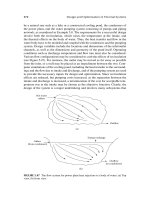
Combinations of L and γ may cause the following cases of meshing and contact
inside the cycle of meshing:
(i) The bearing contact is formed by points of tangency of tooth surfaces of the pinion
and gear.
(ii) Edge contact occurs in the process of meshing wherein a curve (it is an edge of one
of the mating surfaces) is in mesh with a surface (the other mating surface).
(iii) The bearing contact is formed as the result of a combination of the meshing in
cases (i) and (ii).
Investigation of meshing in the case of edge contact is discussed in Section 9.6.
P1: JXR
CB672-17 CB672/Litvin CB672/Litvin-v2.cls February 27, 2004 0:58
17.6 Longitudinal Crowning of Pinion by a Plunging Disk 487
The output of TCA has been obtained for the previous example wherein edge contact
has not occurred. The results obtained by computation are as follows:
(1) The path of contact is indeed oriented longitudinally [Figs. 17.5.2(a) and
17.5.2(b)].
(2) Error E of the center distance does not cause transmission errors, but causes the
shift of the bearing contact.
(3) However, errors of alignment γ and λ cause a discontinuous linear function
of transmission errors φ
2
(φ
σ
) [Fig. 17.5.2(c)]. Therefore, the transfer of meshing
from one pair of teeth to the neighboring one is accompanied with high acceleration,
and vibration and noise become inevitable.
Noise and vibration of all types of Novikov–Wildhaber gear drives are inevitable if
only profile crowning of pinion-gear tooth surfaces is provided. This statement is true
as well for Novikov–Wildhaber gears of the existing design. Substantial reduction of
acceleration is obtained by double-crowning of the pinion that provides a parabolic
function of transmission errors as discussed in Section 9.2. Such a function is able to
absorb linear functions of transmission errors caused by misalignment. It follows from
the discussion above that design of a gear drive formed by a double-crowned pinion
and a profile-crowned gear is the precondition for reduction of noise and vibration and
localization of bearing contact.
17.6 LONGITUDINAL CROWNING OF PINION BY A PLUNGING DISK
Longitudinal crowning of the pinion tooth surface, in addition to profile crowning,
is applied for transformation of the shape of the function of transmission errors and
reduction of noise and vibration. We recall that errors of shaft angle and lead an-
gle cause a discontinuous linear function of transmission errors [see Section 17.5 and
Fig. 17.6.2(c)], and high acceleration and vibration of the gear drive become inevitable.
Generation of the pinion by a plunging disk enables avoidance of this defect.
Application of a Disk-Shaped Tool
Figure 17.6.1 shows the generating disk and the pinion in the 3D-space. The surface of
the disk is a surface of revolution and is conjugated to the profile-crowned surface of
the pinion. The profile-crowned surface
σ
of the pinion is a helicoid and is determined
as the envelope to the parabolic rack-cutter (see Section 17.4).
It is assumed that during the process of generation of the pinion, the pinion performs
a screw motion about its axis and is plunged with respect to the generating disk that is
held at rest. The plunging motion of the pinion is performed along the shortest center
distance between the axes of the disk and the pinion. The plunging motion is executed
by a parabolic function (see below). The generating disk performs rotation about its
axis, but the angular velocity of rotation is not related to the process of generation. It
is assumed that the two components of pinion screw motion and the plunging motion
are provided to the pinion. However, one or two of these three components of motions
may be provided to the generating disk but not to the pinion.