Gear Geometry and Applied Theory Episode 2 Part 6 ppsx
Bạn đang xem bản rút gọn của tài liệu. Xem và tải ngay bản đầy đủ của tài liệu tại đây (744.83 KB, 30 trang )
P1: GDZ/SPH P2: GDZ
CB672-15 CB672/Litvin CB672/Litvin-v2.cls February 27, 2004 0:44
15.8 Undercutting and Pointing 433
The derivation of line L is based on the following considerations:
(i) Equation (15.8.1) yields
∂r
c
∂u
c
du
c
dt
+
∂r
c
∂θ
c
dθ
c
dt
=−v
(cσ)
c
. (15.8.3)
Here, ∂r
c
/∂u
c
, ∂r
c
/∂θ
c
, and v
(cσ)
c
are three-dimensional vectors represented in sys-
tem S
c
of the pinion rack-cutter.
(ii) Equation (15.8.2) yields
∂ f
∂u
c
du
c
dt
+
∂ f
∂θ
c
dθ
c
dt
=−
∂ f
∂ψ
σ
dψ
σ
dt
. (15.8.4)
(iii) Equations (15.8.3) and (15.8.4) represent a system of four linear equations in two
unknowns: du
c
/dt and dθ
c
/dt. This system has a certain solution for the unknowns
if matrix
A =
∂r
c
∂u
c
∂r
c
∂θ
c
−v
(cσ)
c
∂ f
∂u
c
∂ f
∂θ
c
−
∂ f
∂ψ
σ
dψ
σ
dt
(15.8.5)
has the rank r = 2. This yields
1
=
∂x
c
∂u
c
∂x
c
∂θ
c
−v
(cσ)
xc
∂y
c
∂u
c
∂y
c
∂θ
c
−v
(cσ)
yc
∂ f
∂u
c
∂ f
∂θ
c
−
∂ f
∂ψ
σ
dψ
σ
dt
= 0 (15.8.6)
2
=
∂x
c
∂u
c
∂x
c
∂θ
c
−v
(cσ)
xc
∂z
c
∂u
c
∂z
c
∂θ
c
−v
(cσ)
zc
∂ f
∂u
c
∂ f
∂θ
c
−
∂ f
∂ψ
σ
dψ
σ
dt
= 0 (15.8.7)
3
=
∂y
c
∂u
c
∂y
c
∂θ
c
−v
(cσ)
yc
∂z
c
∂u
c
∂z
c
∂θ
c
−v
(cσ)
zc
∂ f
∂u
c
∂ f
∂θ
c
−
∂ f
∂ψ
σ
dψ
σ
dt
= 0 (15.8.8)
P1: GDZ/SPH P2: GDZ
CB672-15 CB672/Litvin CB672/Litvin-v2.cls February 27, 2004 0:44
434 Modified Involute Gears
4
=
∂x
c
∂u
c
∂x
c
∂θ
c
−v
(cσ)
xc
∂y
c
∂u
c
∂y
c
∂θ
c
−v
(cσ)
yc
∂z
c
∂u
c
∂z
c
∂θ
c
−v
(cσ)
zc
= 0. (15.8.9)
Equation (15.8.9) yields the equation of meshing f (u
c
,θ
c
,ψ
σ
) = 0 and is not ap-
plied for investigation of singularities. The requirement that determinants
1
,
2
,
and
3
must be equal to zero simultaneously may be represented as
2
1
+
2
2
+
2
3
= 0. (15.8.10)
Equation (15.8.10) enables us to obtain for determination of singularities the fol-
lowing function:
F (u
c
,θ
c
,ψ
σ
) = 0 (15.8.11)
NOTE. In most cases, it is sufficient for derivation of function F = 0 to use instead
of (15.8.10) only one of the three following equations:
1
= 0,
2
= 0,
3
= 0. (15.8.12)
An exceptional case, when application of (15.8.10) is required, is discussed in
Section 6.3.
Singularities of the pinion may be avoided by limitation by line L of the rack-cutter
surface
c
that generates the pinion. The determination of L [Fig. 15.8.1(a)] is based
on the following procedure:
(1) Using equation of meshing f (u
c
,θ
c
,ψ
σ
) = 0, we may obtain in the plane of pa-
rameters (u
c
,θ
c
) the family of contact lines of the rack-cutter and the pinion. Each
contact line is determined for a fixed parameter of motion ψ
σ
.
(2) The sought-for limiting line L is determined in the space of parameters (u
c
,θ
c
)by
simultaneous consideration of equations f = 0 and F = 0 [Fig. 15.8.1(a)]. Then,
we can obtain the limiting line L on the surface of the rack-cutter [Fig. 15.8.1(b)].
The limiting line L on the rack-cutter surface is formed by regular points of the rack-
cutter, but these points will generate singular points on the pinion tooth surface.
Limitations of the rack-cutter surface by L enable us to avoid singular points on the
pinion tooth surface. Singular points on the pinion tooth surface can be obtained by
coordinate transformation of line L on rack-cutter surface
c
to surface
σ
.
Pointing
Pointing of the pinion means that the width of the topland becomes equal to zero.
Figure 15.8.2(a) shows the cross sections of the pinion and the pinion rack-cutter. Point
A
c
of the rack-cutter generates the limiting point A
σ
of the pinion when singularity of
the pinion is still avoided. Point B
c
of the rack-cutter generates point B
σ
of the pinion
profile. Parameter s
a
indicates the chosen width of the pinion topland. Parameter α
t
indicates the pressure angle at point Q. Parameters h
1
and h
2
indicate the limitation of
P1: GDZ/SPH P2: GDZ
CB672-15 CB672/Litvin CB672/Litvin-v2.cls February 27, 2004 0:44
15.9 Stress Analysis 435
(mm)
(mm)
Figure 15.8.1: Contact lines L
cσ
and limiting line L: (a) in plane (u
c
, θ
c
); (b) on surface
c
.
location of limiting points A
c
and B
c
of the rack-cutter profiles. Figure 15.8.2(b) shows
functions h
1
(N
1
) and h
2
(N
1
)(N
1
is the pinion tooth number) obtained for the following
data: α
d
= 25
◦
, β = 30
◦
, parabola coefficient of pinion rack-cutter a
c
= 0.002 mm
−1
,
s
a
= 0.3 m, parameter s
12
= 1.0 [see Eq. (15.2.3)], and module m = 1 mm.
15.9 STRESS ANALYSIS
This section covers stress analysis and investigation of formation of bearing contact
of contacting surfaces. The performed stress analysis is based on the finite element
method [Zienkiewicz & Taylor, 2000] and application of a general computer program
[Hibbit, Karlsson & Sirensen, Inc., 1998]. An enhanced approach for application of
finite element analysis is presented in Section 9.5.
P1: GDZ/SPH P2: GDZ
CB672-15 CB672/Litvin CB672/Litvin-v2.cls February 27, 2004 0:44
436 Modified Involute Gears
-
Figure 15.8.2: Permissible dimensions h
1
and h
2
of rack-cutter: (a) cross sections of pinion and rack-
cutter; (b) functions h
1
(N
1
) and h
2
(N
1
).
Using the developed approach for stress analysis, the following advantages can be
obtained:
•
Finite element models of the gear drive can be automatically obtained for any position
of pinion and gear obtained from TCA. Stress convergence is assured because there
is at least one point of contact between the contacting surfaces.
•
Assumption of load distribution in the contact area is not required because the contact
algorithm of the general computer program [Hibbit, Karlsson & Sirensen, Inc., 1998]
is used to get the contact area and stresses by application of torque to the pinion while
the gear is considered at rest.
P1: GDZ/SPH P2: GDZ
CB672-15 CB672/Litvin CB672/Litvin-v2.cls February 27, 2004 0:44
1
2
3
Figure 15.9.1: Whole gear drive finite element model.
1
2
3
Figure 15.9.2: Contacting model of five pairs of teeth derived for stress analysis.
437
P1: GDZ/SPH P2: GDZ
CB672-15 CB672/Litvin CB672/Litvin-v2.cls February 27, 2004 0:44
(Ave. Crit.: 75%)
S, Mises
+2.724e-03
+7.653e+01
+1.531e+02
+2.296e+02
+3.061e+02
+3.827e+02
+4.592e+02
+5.357e+02
+6.122e+02
+6.888e+02
+7.653e+02
+8.418e+02
+9.184e+02
1
2
3
Bending Stress: 136.8 MPa
(MPa)
Figure 15.9.3: Contact and bending stresses in the middle point of the path of contact on the pinion
tooth surface for a modified involute helical gear drive wherein the generation is performed by plunging
of the grinding worm.
Contact Stresses (MPa)
(rad)
Bending Stresses (MPa)
(rad)
φ
φ
Figure 15.9.4: Contact and bending stresses during the cycle of meshing of the pinion.
438
P1: GDZ/SPH P2: GDZ
CB672-15 CB672/Litvin CB672/Litvin-v2.cls February 27, 2004 0:44
15.9 Stress Analysis 439
(Ave. Crit.: 75%)
S, Mises
+1.569e+03
+4.956e-04
+7.500e+01
+1.500e+02
+2.250e+02
+3.000e+02
+3.750e+02
+4.500e+02
+5.250e+02
+6.000e+02
+6.750e+02
+7.500e+02
+8.250e+02
+9.000e+02
1
2
3
Bending Stress: 76.9 MPa
(MPa)
Figure 15.9.5: Contact and bending stresses in the middle point of the path of contact on a conventional
involute helical pinion with error γ = 3 arcmin: edge contact with high stresses occurs.
•
Finite element models of any number of teeth can be obtained. As an example,
Fig. 15.9.1 shows a whole gear drive finite element model. However, such a model is
not recommended if an exact definition of the contact ellipse is required. Three- or
five-tooth models are more adequate in such a case. Figure 15.9.2 shows a contacting
model of five pairs of teeth derived for stress analysis.
The use of several teeth in the models has the following advantages:
(i) Boundary conditions are far enough from the loaded areas of the teeth.
(ii) Simultaneous meshing of two pairs of teeth can occur due to the elasticity of sur-
faces. Therefore, the load transition at the beginning and at the end of the path of
contact can be studied.
Numerical Example
Stress analysis has been performed for the gear drive with the design parameters shown
in Table 15.7.1. A finite element model of three pairs of contacting teeth has been
applied for each chosen point of the path of contact. Elements C3D8I [Hibbit, Karlsson
& Sirensen, Inc., 1998] of first order (enhanced by incompatible modes to improve their
P1: GDZ/SPH P2: GDZ
CB672-15 CB672/Litvin CB672/Litvin-v2.cls February 27, 2004 0:44
440 Modified Involute Gears
(Ave. Crit.: 75%)
S, Mises
+1.598e-03
+9.215e+01
+1.843e+02
+2.764e+02
+3.686e+02
+4.607e+02
+5.529e+02
+6.450e+02
+7.372e+02
+8.293e+02
+9.215e+02
+1.014e+03
+1.106e+03
1
2
3
Bending Stress: 135.6 MPa
(MPa)
Figure 15.9.6: Contact and bending stresses in the middle point of the path of contact on the pinion
tooth surface for a modified involute helical gear drive wherein an error γ = 3 arcmin is considered:
edge contact is avoided.
bending behavior) have been used to form the finite element mesh. The total number
of elements is 45,600 with 55,818 nodes. The material is steel with the properties
of Young’s Modulus E = 2.068 ×10
5
MPa and Poisson’s ratio of 0.29. A torque of
500 Nm has been applied to the pinion. Figure 15.9.3 shows the contact and bending
stresses obtained at the mean contact point for the pinion.
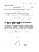
The variation of contact and bending stresses along the path of contact has been also
studied. Figure 15.9.4 illustrates the variation of contact and bending stresses for the
pinion. Stress analysis has also been performed for a conventional helical involute drive
with an error of the shaft angle of γ = 3 arcmin (Fig. 15.9.5). Recall that the tooth
surfaces of an aligned conventional helical gear drive are in line contact, but they are in
point contact with error γ . The results of computation show that error γ causes an
edge contact and an area of severe contact stresses.
Figure 15.9.6 shows the results of finite element analysis for the pinion of a modi-
fied involute helical gear drive wherein an error γ = 3 arcmin occurs. As shown in
Fig. 15.9.6, a helical gear drive with modified geometry is indeed free of edge contact
and areas of severe contact stresses.
P1: JTH
CB672-16 CB672/Litvin CB672/Litvin-v2.cls February 27, 2004 0:51
16 Involute Helical Gears with Crossed Axes
16.1 INTRODUCTION
Involute helical gears are widely applied in the industry for transformation of rotation
between parallel and crossed axes. Figure 16.1.1 shows an involute helical gear drive
with crossed axes in 3D-space. A gear drive formed by a helical gear and a worm gear is
a particular case of a gear drive with crossed axes (Figure 16.1.2). Gear tooth surfaces
are in line contact for involute helical gear drives with parallel axes and in point contact
for involute helical gear drives with crossed axes.
The theory of involute gears and research in this area have been presented by Litvin
[1968], Colbourne [1987], Townsend [1991], and Litvin et al. [1999, 2001a, 2001c,
2001d] and the theory of shaving and honing technological processes are discussed
in the works of Townsend [1991] and Litvin et al. [2001a]. Despite the broad in-
vestigation that has been accomplished in this area, the quality of misaligned invo-
lute helical gear drives is still a concern of manufacturers and designers. The main
defects of such misaligned gear drives are (i) appearance of edge contact, (ii) high
levels of vibration, and (iii) the shift of the bearing contact far from the central
location.
To overcome the defects mentioned above, some corrections of gear geometry have
been applied in the past: (i) correction of the lead angle of the pinion (requires regrind-
ing), and (ii) crowning in the areas of the tip of the profile and the edge of the teeth
(based on the experience of manufacturers). A more general approach for localization
of bearing contact has been proposed in Litvin et al. [2001c].
The conditions of meshing of crossed involute gears are represented in this chapter
as follows:
(1) It is shown that a special design (called the canonical one) provides a central location
of bearing contact.
(2) Modification of the representation of lines of action (as the sets of contact points)
allows the following:
(i) representation of an edge contact as the result of the shift of lines of action in
a misaligned gear drive
(ii) relation of the sensitivity to an edge contact with the nominal value of the
crossing angle.
441
P1: JTH
CB672-16 CB672/Litvin CB672/Litvin-v2.cls February 27, 2004 0:51
442 Involute Helical Gears with Crossed Axes
Figure 16.1.1: Involute helical gears with crossed
axes in 3D-space.
Worm
Helical gear
Figure 16.1.2: Gear drive formed by a worm and a helical
gear.
P1: JTH
CB672-16 CB672/Litvin CB672/Litvin-v2.cls February 27, 2004 0:51
16.2 Analysis and Simulation of Meshing of Helical Gears 443
Figure 16.2.1: Illustration of generation of a
screw involute surface.
Algorithms for simulation of meshing (including simulation of edge contact) are
represented. The theory is supported by numerical examples.
16.2 ANALYSIS AND SIMULATION OF MESHING OF HELICAL GEARS
Conceptual Considerations
It is well known [Litvin, 1968, 1989] that a screw involute surface can be generated
by a screw motion of a straight line
MD (Fig. 16.2.1), while in the process of motion
the generating line keeps its orientation as the tangent to the helix on the base cylin-
der. The generated surface is a developed one [Litvin, 1968, 1989; Zalgaller, 1975],
and the normals to the surface along
MD are collinear. Figure 16.2.2(a) shows that
the generated surface is formed as a family of straight lines that are tangent to the
helix on the base cylinder. Tooth surfaces of mating helical gears (in an aligned gear
drive with parallel axes) contact each other along the straight lines
MD mentioned
above.
Assume now that, using coordinate transformation, the lines of contact are repre-
sented in plane that is tangent to both base cylinders of the helical gears with parallel
axes. Figure 16.2.3 shows plane that is tangent to the base cylinder of the pinion.
Angle α
ot1
is the pressure angle in the transverse section. Points O
1
and O
2
represent
the centers of base circles of mating helical gears.
Using coordinate transformation, we represent in plane lines of contact of helical
gears with parallel axes. The lines of contact L represented in plane (Fig. 16.2.3) are
parallel straight lines. Plane of a gear drive with parallel axes is the plane of action
in the fixed coordinate system rigidly connected to the housing of the gear drive.
P1: JTH
CB672-16 CB672/Litvin CB672/Litvin-v2.cls February 27, 2004 0:51
444 Involute Helical Gears with Crossed Axes
Figure 16.2.2: Types of contact of helical gears: (a) line contact in a gear drive with parallel axes, (b)
point contact of crossed helical gears.
We emphasize the special features of the contact lines L:
(1) We recall that Fig. 16.2.1 shows that the screw involute surface is generated by
the screw motion of line
MD. The normals to the screw involute surface (at the
instant position of
MD) are collinear and their orientation does not depend on the
parameter of location of the point on
MD. We may consider that locally MD is a
small strip of the screw involute surface with collinear normals.
Figure 16.2.3: Illustration of contact lines on plane of action .
P1: JTH
CB672-16 CB672/Litvin CB672/Litvin-v2.cls February 27, 2004 0:51
16.2 Analysis and Simulation of Meshing of Helical Gears 445
Figure 16.2.4: Line A of action of involute planar
gearing.
(2) The normal to the screw involute surface at any contact point is orthogonal to the
contact line. Therefore, the normals to the tooth surface are also orthogonal to
contact lines represented on plane .
(3) The normals to the screw involute surface have the same constant orientation in
the plane of action .
Figure 16.2.4 illustrates a planar involute gearing. Line T
1
–T
2
is tangent to the base
circles with radii r
b1
and r
b2
. Simultaneously, line T
1
–T
2
is the common normal to the
meshing involute profiles.
We may extend the conceptual considerations of meshing of a planar involute gearing
to the case of crossed involute helical gears. The gear tooth surfaces of crossed helical
gears contact each other at a point [Fig. 16.2.2(b)], but not at a line as in the case of
helical gears with parallel axes [Fig. 16.2.2(a)]. Figure 16.2.5 shows the base cylinders
of crossed helical gears. It is obvious that the crossed base cylinders of the gears may
have a common tangent line but not a common tangent plane. There are two lines A
1
and A
2
that are tangent to the base cylinders and to the base helices at the same time.
We may call A
1
and A
2
the lines of action of crossed helical gears. Lines A
1
and A
2
correspond to the meshing of the respective sides of the tooth surface.
It is shown below (see Appendices 16.A and 16.B) that the design of crossed helical
gears may be accomplished by observation of a special relation between the shortest
P1: JTH
CB672-16 CB672/Litvin CB672/Litvin-v2.cls February 27, 2004 0:51
446 Involute Helical Gears with Crossed Axes
Figure 16.2.5: Lines of action of aligned
crossed helical gears.
center distance of the gears and the crossing angle. Such a design provides that the lines
of action intersect each other at a point that belongs to the shortest center distance. This
design is called canonical.
Figure 16.2.6 shows the lines of action for which the rules of canonical design are
not observed, and the lines of action A
1
and A
2
are crossed but do not intersect each
other. Each line A
i
is still a tangent to both base cylinders and base helices of the crossed
helical gears. The crossing of lines of action A
1
and A
2
is the result of an error γ of the
nominal value of the shaft angle γ
o
of the gears or the result of an error E of center
distance (see below).
Analytical Determination of Line of Action
of Crossed Helical Gears
Analytical determination of the line of action of misaligned crossed helical gears is
important for detection of edge contact. Edge contact occurs when the line of action is
shifted from the theoretical position and is located outside of the face width (Figs. 16.2.7
and 16.2.8). The derivations that are represented as follows open the way for analytical
determination of the appearance of edge contact. We have represented intersected and
crossed lines of action of crossed helical gears in Figs. 16.2.5 and 16.2.6, respectively.
In addition to this presentation, it is important to represent the lines of action in the
plane that is tangent to the base cylinder of one of the crossed helical gears, say the
P1: JTH
CB672-16 CB672/Litvin CB672/Litvin-v2.cls February 27, 2004 0:51
16.2 Analysis and Simulation of Meshing of Helical Gears 447
Figure 16.2.6: Lines of action in gear drive with error γ
of shaft angle.
Figure 16.2.7: Illustration of (a) plane
1
and
contact lines on
1
, and (b) line of action A
1
and parameters h
1
and m
1
.
P1: JTH
CB672-16 CB672/Litvin CB672/Litvin-v2.cls February 27, 2004 0:51
448 Involute Helical Gears with Crossed Axes
Figure 16.2.8: Illustration of (a) plane
2
and contact
lines on
2
, and (b) line of action A
1
and parameter h
2
.
pinion. Determination of a line of action, say A
1
, in plane (Fig. 16.2.3), requires
the orientation and location.
The orientation of A
1
is determined easily as the one orthogonal to the lines of contact
L. The orientation of lines of action is determined by the lead angle λ
b1
of the pinion
(Fig. 16.2.3). The location of A
1
in plane is determined below. Errors of alignment
(change of shaft angle and shortest center distance) cause the shift of lines of action that
might be accompanied by edge contact. The procedure for computation of the location
of the lines of action is as follows.
Case 1: Error ∆γ of the Crossing Angle (Shaft Angle)
The input parameters of the computations are the radii of base cylinders r
b1
and r
b2
,
the lead angles λ
b1
and λ
b2
on the base cylinders, the nominal value γ
o
of the crossing
angle, and the error γ of the crossing angle.
P1: JTH
CB672-16 CB672/Litvin CB672/Litvin-v2.cls February 27, 2004 0:51
16.2 Analysis and Simulation of Meshing of Helical Gears 449
Step 1: The pressure angle α
∗
on
in the normal section of rack-cutters (see Appendix
16.B) is determined as
cos
2
α
∗
on
=
cos
2
λ
b1
± 2 cos λ
b1
cos λ
b2
cos γ
∗
o
+ cos
2
λ
b2
sin
2
γ
∗
o
. (16.2.1)
Here and below, the superscript “∗” indicates that a parameter of a misaligned gear
drive is considered. The upper and lower signs in Eq. (16.2.1) correspond to helical
gears with the same and opposite directions of helices.
Step 2: The pressure angle α
∗
oti
(i = 1, 2) in the cross section of the pinion or the gear
is determined as
sin α
∗
oti
=
sin α
∗
on
sin λ
bi
(i = 1, 2). (16.2.2)
Step 3: Radii r
∗
oi
indicate the operating pitch cylinders of helical gears used for gen-
eration of helical gears by rack-cutters and are determined as follows:
(i) The operating pitch cylinder of a helical gear is the axode in meshing with the
generating rack-cutter (see Section 16.4). Figure 16.4.2 shows pitch cylinders of
standard helical gears generated by rack-cutters.
(ii) The sum of radii r
∗
oi
(i = 1, 2) of a misaligned gear drive with crossing angle γ
∗
o
differs from the nominal value of center distance E
o
= r
o1
+r
o2
.
(iii) Radii r
∗
oi
are determined as
r
∗
oi
=
r
bi
cos α
∗
oti
(i = 1, 2). (16.2.3)
Step 4: Determination of parameters h
1
and h
2
of the shift of the line of action.
Parameter h
i
(i = 1, 2) is drawn perpendicular to the shifted line of action from point
P
∗
i
(i = 1, 2). Point P
∗
i
is the point of intersection of a cylinder of radius r
∗
oti
with the
line of center distance.
Parameters h
1
and h
2
are determined from the equations (see below)
h
1
=
r
b2
+r
b1
cos α
∗
ot2
cos α
∗
ot1
− E
o
cos α
∗
ot2
sin α
∗
ot2
sin γ
∗
o
sin λ
b1
(16.2.4)
h
2
=
A
B
(16.2.5)
where
A = r
b1
+r
b2
cos α
∗
ot1
cos α
∗
ot2
− E
o
cos α
∗
ot1
(16.2.6)
B = sin λ
b2
sin α
ot1
sin γ
∗
o
+ cos λ
b2
(cos α
∗
ot1
sin α
∗
ot2
− cos α
∗
ot2
sin α
∗
ot1
cos γ
∗
o
).
(16.2.7)
The derivation of equations above is based on the following considerations:
(1) Figure 16.2.7 shows coordinate systems S
f
and S
a
that are rigidly connected to
the pinion. Plane
1
[Fig. 16.2.7(a)] is tangent to the base cylinder of radius r
b1
.
P1: JTH
CB672-16 CB672/Litvin CB672/Litvin-v2.cls February 27, 2004 0:51
450 Involute Helical Gears with Crossed Axes
Figure 16.2.9: Fixed coordinate systems S
f
and S
p
.
Contact lines between pinion tooth surface
1
and generating rack-cutter surface
r 1
are represented in plane
1
as parallel straight lines. The orientation of contact
lines is determined by angle λ
b1
[Fig. 16.2.7(b)].
(2) The line of action A
1
of a misaligned gear drive is shifted with respect to the line
of action A
(o)
1
of an aligned gear drive. The shift is designated by h
1
. The location
of point M
1
on line A
1
is denoted by parameter m
1
[Fig. 16.2.7(b)].
(3) Figure 16.2.8 shows coordinate systems S
b
and S
p
that are rigidly connected to
gear 2. Plane
2
is tangent to the base cylinder of radius r
b2
. Lines of contact
between the gear tooth surface
2
and the generating rack-cutter surface
r 2
are
represented in plane
2
. The orientation of such lines of contact is determined by
angle λ
b2
.
Line of action A
1
is represented as a shifted one. The orientation of A
1
in plane
2
[Fig. 16.2.8(b)] is determined to be orthogonal to the lines of contact, and
its location in plane
2
is represented by parameter h
2
. Parameter h
2
has to be
determined by a computational procedure (see below).
(4) Figure 16.2.9 shows the location and orientation of coordinate systems S
p
and
S
f
. The computational procedure for determination of parameters h
1
and h
2
of the shift of lines of action in planes
1
and
2
is based on the following
considerations:
(i) Figure 16.2.7 represents point M
1
of the line of action (located in plane )by
position vector
r
(1)
f
(h
1
, m
1
, r
b1
,λ
b1
,α
∗
ot1
) (16.2.8)
where h
1
and m
1
are the parameters to be determined.
(ii) Using coordinate transformation from S
b
via S
p
to S
f
we may represent the
position vector of point M
2
of the line of action (located in plane
2
)as
r
(2)
f
(h
2
, r
b2
,λ
b2
,α
∗
ot2
,γ
∗
o
, E
o
). (16.2.9)
P1: JTH
CB672-16 CB672/Litvin CB672/Litvin-v2.cls February 27, 2004 0:51
16.2 Analysis and Simulation of Meshing of Helical Gears 451
(iii) Taking into account that points M
1
and M
2
belong to the same line of action,
vector equation r
(1)
f
(M
1
) = r
(2)
f
(M
2
) yields a system of three linear equations
for determination of h
1
and h
2
and the auxiliary parameter m
1
.
Parameters h
1
and h
2
determine the shifts of the line of action in planes
1
and
2
by Eqs. (16.2.4) and (16.2.5), respectively.
The axial displacements of the line of action with respect to the pinion and the gear
are determined as follows:
Z
1
=
h
1
sin λ
b1
(16.2.10)
Z
2
=
h
2
sin λ
b2
. (16.2.11)
Case 2: Error ∆E of the Center Distance
The determination of the shift of the line of action caused by error E is based on a
similar procedure discussed above, taking into account the following considerations:
(i) γ = 0 and therefore α
∗
on
= α
on
, α
∗
oti
= α
oti
(i = 1, 2).
(ii) However, the center distance due to error E is represented as
E
∗
= E
o
+ E. (16.2.12)
(iii) Then, the computational procedure enables us to obtain the shifts h
1
(E) and
h
2
(E) caused by E, and the corresponding axial displacements Z
1
and Z
2
.
The shifts of the line of action in plane
1
caused by errors γ and E are repre-
sented in Figs. 16.2.10(a) and 16.2.10(b) by functions Z
1
(γ, γ
o
) and Z
1
(E,γ
o
),
Figure 16.2.10: Illustration of variation of the shift Z
1
of the line of action due to errors (a) γ and
(b) E.
P1: JTH
CB672-16 CB672/Litvin CB672/Litvin-v2.cls February 27, 2004 0:51
452 Involute Helical Gears with Crossed Axes
respectively. Here, γ
o
is the nominal crossing angle. In both cases, the sensitivity of the
shift becomes very high for a nominal crossing angle γ
o
of small value. In this case,
edge contact is inevitable due to the large shift Z
1
that requires unreasonable axial
dimensions of the gears. The reduction of shift Z
1
may be obtained (i) by changing
the lead angle λ
bi
and regrinding one of the gears, and (ii) by modification of the tooth
surface geometry [Litvin et al., 2001c].
16.3 SIMULATION OF MESHING OF CROSSED HELIC AL GEARS
The algorithm for simulation of meshing and contact of cross helical gears is based on
simulation of continuous tangency of gear tooth surfaces (see Section 9.4). The equations
of tooth surfaces
1
and
2
of the gears and the unit normals are considered in a fixed
coordinate system S
f
rigidly connected to the housing. The conditions of continuous
tangency are represented as follows:
r
(1)
f
(u
1
,ψ
1
,φ
1
) − r
(2)
f
(u
2
,ψ
2
,φ
2
) = 0 (16.3.1)
n
(1)
f
(ψ
1
,φ
1
) − n
(2)
f
(ψ
2
,φ
2
) = 0. (16.3.2)
Here, (u
i
,ψ
i
)(i = 1, 2) are the surface parameters, φ
i
are the angles of gear ro-
tation, and r
(i )
f
is the position vector of surface
i
. Vector equations (16.3.1) and
(16.3.2) yield a system of five independent nonlinear equations in six unknowns tak-
ing into account that |n
(1)
f
|=|n
(2)
f
|=0. One of the parameters, say φ
1
, is chosen as
the input one, and the solution of the five nonlinear equations is an iterative pro-
cess.
The solution of five nonlinear equations discussed above is based on application of the
theorem of implicit function system existence [Korn & Korn, 1968] and is represented
by functions
{u
1
(φ
1
),ψ
1
(φ
1
), u
2
(φ
1
),ψ
2
(φ
1
),φ
2
(φ
1
)}∈C
1
(16.3.3)
that allow us to obtain the path of contact on the gear tooth surface and the transmis-
sion function φ
2
(φ
1
). The deviations of φ
2
(φ
1
) from the theoretical value represent the
transmission errors
φ
2
(φ
1
) = φ
2
(φ
1
) −
N
1
N
2
φ
1
. (16.3.4)
The Jacobian of the system of equations provided by vector equations (16.3.1) and
(16.3.2) has to differ from zero, and this is the sign that surfaces
1
and
2
are in point
contact but not in line contact.
It was mentioned above that the existence of an edge contact of tooth surfaces
1
and
2
(instead of surface-to-surface contact) in misaligned gear drives is not excluded.
In the case of edge contact, we have surface-to-curve meshing, and the algorithm for
P1: JTH
CB672-16 CB672/Litvin CB672/Litvin-v2.cls February 27, 2004 0:51
16.3 Simulation of Meshing of Crossed Helical Gears 453
simulation of meshing is determined as follows:
r
(1)
f
(u
1
(ψ
1
),ψ
1
,φ
1
) −r
(2)
f
(u
2
,ψ
2
,φ
2
) = 0 (16.3.5)
∂r
(1)
f
∂ψ
1
· n
(2)
f
= 0. (16.3.6)
Here, r
(1)
f
(u
1
(ψ
1
),ψ
1
,φ
1
) represents at φ
1
= const the instantaneous position of the edge
of the pinion tooth surface that is in mesh with the surface of gear 2; r
(2)
f
(u
2
,ψ
2
,φ
2
)
represents at φ
2
= const the instantaneous position of the gear tooth surface. Vector
∂r
(1)
f
/∂ψ
1
represents the tangent to the edge of the pinion. Observation of Eqs. (16.3.5)
and (16.3.6) means that the normal to surface
2
is perpendicular to the edge of the
pinion tooth surface and the pinion edge and surface
2
are indeed in mesh. Similar
equations can be applied wherein the surface of the pinion is in mesh with the edge of
the gear tooth surface. Application of the developed computer program for TCA (Tooth
Contact Analysis) shows (i) the change of shortest center distance and crossing angle
do not cause transmission errors; and (ii) however, errors γ and E cause the shift
of bearing contact from the working area.
Figure 16.3.1 illustrates the shift of bearing contact on the pinion tooth surfaces from
position I to position II due to error γ obtained for a crossed helical gear drive. The
results obtained by numerical simulation are in agreement with the results obtained by
application of the equations of the line of action.
Figure 16.3.1: Illustration of zones of contact on tooth
surface of aligned and misaligned gear drives: I and II are
zones of contact that correspond to γ = 0 and γ = 0,
respectively.
P1: JTH
CB672-16 CB672/Litvin CB672/Litvin-v2.cls February 27, 2004 0:51
454 Involute Helical Gears with Crossed Axes
(arc sec)
(rad)
Figure 16.3.2: Function of transmission errors in a gear drive formed by an Archimedes worm and an
involute helical gear.
Numerical Example: Worm-Gear Drive
Conjugation of tooth surfaces and zero transmission error are provided in a gear drive
formed by an involute worm and an involute helical gear. Application of a worm whose
thread surface differs from an involute screw one is accompanied with transmission
errors as shown in Fig. 16.3.2. The design parameters of the gear drive are represented
in Table 16.3.1. The output of the developed TCA computer program (Fig. 16.3.2) shows
that meshing of an Archimedes worm with a helical involute gear is accompanied with
large transmission errors, and the function of transmission errors is positive instead
of negative. Only a negative function of transmission errors wherein the driven gear is
lagging with respect to the worm gear should be applied in a misaligned gear drive. Then
the contact ratio of the gear drive might be increased due to the elastic deformations
of the driven gear of the drive. The obtained results of simulation of meshing show
that meshing of an involute helical gear with a worm that differs from an involute one
should not be applied in the design.
Table 16.3.1: Design parameters of a worm and an involute helical gear
Number of threads of the worm, N
1
5
Number of teeth of the gear, N
2
48
Normal module, m
pn
4.0mm
Normal pressure angle, α
pn
25
◦
Helix angle of the worm, β
p1
70
◦
Helix angle of the gear, β
p2
20
◦
Worm face width, F
1
70 mm
Gear face width, F
2
30 mm
P1: JTH
CB672-16 CB672/Litvin CB672/Litvin-v2.cls February 27, 2004 0:51
16.4 Generation of Conjugated Tooth Surfacesof Crossed Helical Gears 455
16.4 GENERATION OF CONJUGATED TOOTH SURFACES
OF CROSSED HELIC AL GEARS
Generation of a Helical Gear
A helical gear can be generated by a hob or by a shaper. Consideration of generation
of a helical gear by a rack-cutter is useful for considering conceptual aspects of gear
generation. Figure 16.4.1 shows a skew rack-cutter. The generating surface
r
is a plane
[Fig. 16.4.1(a)]. The normal and transverse sections of the rack-cutter are shown in
Fig. 16.4.1(c). Angles 2α
pt
and 2α
pn
are the profile angles in the transverse and normal
sections, respectively. The relations between parameters 2α
pt
and 2α
pn
are presented
in Appendix 16.C and 16.E. The surface parameters of the rack-cutter are denoted as
u
r
[Fig. 16.4.1(d)] and l
r
[Fig. 16.4.1(a)]. Figure 16.4.1(d) shows the normal section
where α
pn
is the normal pressure angle, and s
pn1
and s
pn2
represent the tooth thickness
and the space width on the normal section, respectively.
Coordinate systems S
r
and S
1
are rigidly connected to the rack-cutter and the pinion
1 [Fig. 16.4.1(b)]. In the process for generation, the pinion and the rack-cutter perform
Figure 16.4.1: Schematic illustration of (a) skew rack-cutter, (b) generation by rack-cutter of a helical
gear, (c) transverse and normal sections of rack-cutter, and (d) relation of s
pn1
and s
pn2
in normal
section.
P1: JTH
CB672-16 CB672/Litvin CB672/Litvin-v2.cls February 27, 2004 0:51
456 Involute Helical Gears with Crossed Axes
related rotation and translation [Fig. 16.4.1(b)]. Plane
r
of the rack-cutter and the
pinion cylinder of radius r
p1
are axodes that roll over each other in relative motion.
Consider that generating plane
r
is given and determination of the surface
1
of
the pinion as the envelope to
r
is required. The determination of
1
is based on the
equations
r
1
(u
r
, l
r
,ψ
1
) = M
1r
(ψ
1
)r
r
(u
r
, l
r
) (16.4.1)
f
1
(u
r
, l
r
,ψ
1
) = 0 (16.4.2)
where ψ
1
is the generalized parameter of motion in meshing of the rack-cutter with the
helical gear. Vector function r
1
(u
r
, l
r
,ψ
1
) represents the family of rack-cutter surfaces
in coordinate system S
1
. Equation of meshing (16.4.2) may be determined by one of the
following alternative approaches (see Chapter 6):
∂r
1
∂u
r
×
∂r
1
∂l
r
·
∂r
1
∂ψ
1
= 0 (16.4.3)
or
N
r
· v
(r 1)
r
= 0 (16.4.4)
where N
r
is the normal to the rack-cutter generating plane and v
(r 1)
r
is the relative
(sliding) velocity of the rack-cutter with respect to the pinion. Vectors N
r
and v
(r 1)
r
are
represented in coordinate system
r
(for the purpose of simplification of derivations).
Equations (16.4.1) and (16.4.2) considered simultaneously represent the pinion tooth
surface by three related parameters. Taking into account that u
r
and l
r
are linear pa-
rameters, it is easy to eliminate one of them and represent surface
i
in two-parameter
form, for instance, as r
1
(ψ
1
, u
r
). The generated pinion tooth surface
1
is a screw invo-
lute one. Such a surface may be represented as the one generated by a straight line
MD
performing a screw motion; line
MD is shown in Fig. 16.2.1 (see Section 16.2).
The lines of contact of rack-cutter surfaces
r
and
1
may be represented in various
coordinate systems, for instance in coordinate system S
r
. Such lines of contact (consid-
ering simultaneously vector function r
r
(u
r
, l
r
) and equation of meshing (16.4.2)) are
represented in S
r
by the vector function
r
r
(u
r
(ψ
1
), l
r
(ψ
1
)). (16.4.5)
It is useful for conceptual purposes to represent the lines of contact L
r 1
in coordinate
system S
q
that is rigidly connected to a plane that is tangent to the base cylinder of
pinion 1. Then we obtain the family of contact lines as
r
q
(ψ
1
) = M
qa
M
ar
r
r
(u
r
(ψ
1
), l
r
(ψ
1
)). (16.4.6)
The lines of contact L
r 1
of
r
and
1
are represented in S
q
as a family of parallel straight
lines. Such a family is similar to the family of lines of contact shown in Fig. 16.2.3.
Generation of Conjugated Crossed Helical Gears
Crossed helical gears perform rotation between crossed axes with a constant gear ra-
tio. The idea of generation of conjugated surfaces of pinion 1 and gear 2 is based on
P1: JTH
CB672-16 CB672/Litvin CB672/Litvin-v2.cls February 27, 2004 0:51
16.4 Generation of Conjugated Tooth Surfacesof Crossed Helical Gears 457
Figure 16.4.2: Schematic of generation of
crossed helical gears.
application of two generating rack-cutters that are provided with two coinciding gen-
erating planes
(1)
r
and
(2)
r
. However, planes
(1)
r
and
(2)
r
may slide over each other.
Magnitudes s
pn1
and s
pn2
[Fig. 16.4.1(d)] represent in the normal section the tooth thick-
nesses of the rack-cutters applied for generation of the pinion and the gear. Parameters
s
pn1
and s
pn2
are related as
s
pn1
+ s
pn2
= πm
pn
(16.4.7)
where m
pn
is the normal module.
The schematic of the generation of conjugated crossed helical gears is shown in
Fig. 16.4.2. Axes z
1
and z
2
of pinion 1 and gear 2 are crossed and form angle γ
p
.
The shortest distance between the axes in the case of generation of standard gears is
E
p
= r
p1
+r
p2
(16.4.8)
where r
pi
(i = 1, 2) is the radius of the pitch cylinder.
During the process of generation of pinion 1, the pinion is rotated with angular
velocity ω
(1)
about z
1
, and the rack-cutter
(1)
r
is translated with velocity
v
(1)
r
= ω
(1)
1
× O
1
P . (16.4.9)
Similarly, gear 2 is rotated with angular velocity ω
2
and the rack-cutter
(2)
r
is translated
with velocity
v
(2)
r
= ω
(2)
1
× O
2
P . (16.4.10)
Here,
O
1
P and O
2
P are the radii of the pitch cylinders of the pinion and the gear.
Planes
1
and
2
are perpendicular to the center distance and pass through point P of
the center distance. Skew rack-cutters
(1)
r
and
(2)
r
have coinciding generating planes
that may slide over each other during the process of generation. Angular velocities ω
(1)
and ω
(2)
are related as m
12
= ω
(1)
/ω
(2)
where m
12
is the gear ratio.
The represented process of generation enables us to obtain tooth surfaces
1
and
2
of the pinion and the gear that are in point contact at any instant but not in line contact.