Gear Geometry and Applied Theory Episode 2 Part 5 pptx
Bạn đang xem bản rút gọn của tài liệu. Xem và tải ngay bản đầy đủ của tài liệu tại đây (449.21 KB, 30 trang )
P1: GDZ/SPH P2: GDZ
CB672-14 CB672/Litvin CB672/Litvin-v2.cls February 27, 2004 0:39
14.10 Nomenclature 403
parabolic function of transmission errors that is able to absorb the linear functions of
transmission errors caused by misalignments.
14.10 NOMENCLATURE
α
n
rack profile angle in normal section (Fig. 14.4.7)
α
t
rack profile angle in transverse section (Fig. 14.4.7)
β
k
(k = p,ρ) helix angle on pitch cylinder (k = p), on cylinder of
radius ρ (k = ρ) (Figs. 14.2.1 and 14.4.7)
λ
i
(i = p, b,ρ) lead angle on the pitch cylinder (i = p), on the base cylinder
(i = b), and on the cylinder of radius ρ (Figs. 14.2.1, 14.4.5
and 14.4.7)
µ
1
half of the angular width of the tooth space on the base circle of
gear 1 (Fig. 14.3.2)
θ, θ
1
, and θ
2
surface parameter of the screw involute surface (Figs. 14.3.2
and 14.3.3)
φ, φ
1
, and φ
2
angle of gear rotation (Figs. 14.4.1 and 14.5.1)
η
2
half of the angular tooth thickness on pitch circle of gear 2
E shortest axes distance (Fig. 14.5.1)
F
(12,n)
normal component of contact force (Fig. 14.8.2)
H lead (Fig. 14.2.1)
l axial dimension of helical gear [Fig. 14.7.1(b)]
m
12
gear ratio
m
c
gear contact ratio
N surface normal
n surface unit normal
p
n
circular pitch measured perpendicular to the direction of skew
teeth of the rack [Fig. 14.4.7(c)]
p
t
circular pitch in the cross section [Fig. 14.4.7(c)]
P
n
and P
t
diametral pitches that correspond to p
n
and p
t
p = H /2π screw parameter
q orientation angle of straight contact lines on rack tooth surface
(Fig. 14.4.3)
r
b
radius of base cylinder (Fig. 14.4.4)
r
o
radius of operating pitch cylinder, axode
r
pi
radius of pitch cylinder i (Figs. 14.3.2 and 14.3.3)
s rack displacement (Fig. 14.4.1)
s
t
tooth thickness on the pitch circle in the cross section
u surface parameter of a screw involute surface
w
t
space width measured on the pitch circle in cross section
X
(12)
f
, Y
(12)
f
, Z
(12)
f
components of contact force (Figs. 14.8.2 and 14.8.3)
P1: GDZ/SPH P2: GDZ
CB672-15 CB672/Litvin CB672/Litvin-v2.cls February 27, 2004 0:44
15 Modified Involute Gears
15.1 INTRODUCTION
Involute gears, spur and helical ones, are widely used in reducers, planetary gear trains,
transmissions, and many other industrial applications. The level of sophistication in the
design and manufacture of such gears (by hobbing, shaping, and grinding) is impressive.
The geometry, design, and manufacture of helical gears was the subject of research
presented in the works of Litvin et al. [1995, 1999, 2001a, 2003], Stosic [1998], and
Feng et al. [1999].
The advantage of involute gearing in comparison with cycloidal gearing is that the
change of center distance does not cause transmission errors. However, the practice
of design and the test of bearing contact and transmission errors show the need for
modification of involute gearing, particularly of helical gears. Figure 15.1.1 shows a 3D
model of a modified involute helical gear drive.
The existing design and manufacture of involute helical gears provide instantaneous
contact of tooth surfaces along a line. The instantaneous line of contact of conjugated
tooth surfaces is a straight line L
0
that is the tangent to the helix on the base cylinder
(Fig. 15.1.2). The normals to the tooth surface at any point of line L
0
are collinear and
they intersect in the process of meshing with the instantaneous axis of relative motion
that is the tangent to the pitch cylinders. The concept of pitch cylinders is discussed in
Section 15.2.
The involute gearing is sensitive to the following errors of assembly and manufacture:
(i) the change γ of the shaft angle, and (ii) the variation of the screw parameter (of one
of the mating gears). Angle γ is formed by the axes of the gears when they are crossed,
but not parallel, due to misalignment (see Fig. 15.4.4). Such errors cause discontinuous
linear functions of transmission errors which result in vibration and noise, and these
errors may also cause edge contact wherein meshing of a curve and a surface occurs
instead of surface-to-surface contact (see Section 15.9). In a misaligned gear drive, the
transmission function varies in each cycle of meshing (a cycle for each pair of meshing
teeth). Therefore the function of transmission errors is interrupted at the transfer of
meshing between two pairs of teeth [see Fig. 15.4.6(a)].
This chapter covers (i) computerized design, (ii) methods for generation, (iii) simu-
lation of meshing, and (iv) enhanced stress analysis of modified involute helical gears.
404
P1: GDZ/SPH P2: GDZ
CB672-15 CB672/Litvin CB672/Litvin-v2.cls February 27, 2004 0:44
15.1 Introduction 405
Figure 15.1.1: Modified involute helical gear
drive.
The approaches proposed for modification of conventional involute helical gears are
based on the following basic ideas:
(i) Line contact of tooth surfaces is substituted by instantaneous point contact.
(ii) The point contact of tooth surfaces is achieved by crowning of the pinion in the
profile and longitudinal directions. The tooth surface of the gear is a conventional
screw involute surface.
Contact lines L
0
Base cylinder helix
Figure 15.1.2: Contact lines on an involute
helical tooth surface.
P1: GDZ/SPH P2: GDZ
CB672-15 CB672/Litvin CB672/Litvin-v2.cls February 27, 2004 0:44
406 Modified Involute Gears
Screw Involute
surface
Profile-crowned pinion
tooth surface
Screw Involute
surface
Double-crowned pinion
tooth surface
(a)
(b)
Figure 15.1.3: Crowning of pinion tooth surface.
(iii) Profile crowning provides localization of bearing contact, and the path of contact
on the tooth surface of the pinion or the gear is oriented longitudinally (see Section
15.4).
(iv) Longitudinal crowning enables us to provide a parabolic function of transmission
errors of the gear drive. Such a function absorbs discontinuous linear functions
of transmission errors caused by misalignment and therefore reduces noise and
vibration (see Section 15.7). Figures 15.1.3(a) and 15.1.3(b) illustrate the profile-
crowned and double-crowned pinion tooth surface.
(v) Profile crowning of the pinion tooth surface is achieved by deviation of the gener-
ating tool surface in the profile direction (see Section 15.2). Longitudinal crown-
ing of the pinion tooth surface can be achieved by: (i) plunging of the tool, or
(ii) application of modified roll (see Sections 15.5 and 15.6).
(vi) The effectiveness of the procedure of stress analysis is enhanced by automatization
of development of the contacting model of several pairs of teeth. The derivation
of the model is based on application of the equations of the tooth surfaces; CAD
codes for building the model are not required. Details of application of the proposed
approaches are presented in Section 15.9.
P1: GDZ/SPH P2: GDZ
CB672-15 CB672/Litvin CB672/Litvin-v2.cls February 27, 2004 0:44
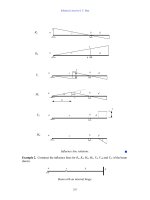
15.2 Axodes of Helical Gears and Rack-Cutters 407
-
Figure 15.2.1: Axodes of pinion, gear, and rack-cutter: (a) axodes; (b) tooth surfaces of two skew
rack-cutters.
15.2 AXODES OF HELIC AL GEARS AND RACK-CUTTERS
The concept of generation of pinion and gear tooth surfaces is based on application of
rack-cutters. The idea of the rack-cutters is the basis for design of such generating tools
as disks and worms. The concept of axodes is applied when the meshing and generation
of helical gears are considered.
Figure 15.2.1(a) shows the case wherein gears 1 and 2 perform rotation about parallel
axes with angular velocities ω
(1)
and ω
(2)
with the ratio ω
(1)
/ω
(2)
= m
12
where m
12
is
the constant gear ratio. The axodes of the gears are two cylinders of radii r
p1
and r
p2
,
and the line of tangency of the cylinders designated as P
1
–P
2
is the instantaneous axis
of rotation (see Chapter 3). The axodes roll over each other without sliding.
The rack-cutter and the gear being generated perform related motions:
(i) translational motion with velocity
v = ω
(1)
× O
1
P = ω
(2)
× O
2
P (15.2.1)
where P belongs to P
1
–P
2
(ii) rotation with angular velocity ω
(i )
(i = 1, 2) about the axis of the gear.
P1: GDZ/SPH P2: GDZ
CB672-15 CB672/Litvin CB672/Litvin-v2.cls February 27, 2004 0:44
408 Modified Involute Gears
The axode of the rack-cutter that is meshing with gear i is plane that is tangent to
the gear axodes.
In the existing design, one rack-cutter with a straight-line profile is applied for gen-
eration of pinion and gear tooth surfaces. Then, the tooth surfaces contact each other
along a line and edge contact in a misaligned gear drive is inevitable.
Point contact in the proposed design (instead of line contact) is provided by applica-
tion of two mismatched rack-cutters, as shown in Fig. 15.2.1(b), one of a straight-line
profile for generation of the gear and the other of a parabolic profile for generation of
the pinion. This method of generation provides a profile-crowned pinion.
It is shown below (see Sections 15.5 and 15.6) that the pinion in the proposed new de-
sign is double-crowned (longitudinal crowning is provided in addition to profile crown-
ing). Double-crowning of the pinion (proposed in Litvin et al. [2001c]) allows edge
contact to be avoided and provides a favorable function of transmission errors.
Normal and Transverse Sections
The normal section a−a of the rack-cutter is obtained by a plane that is perpendicular to
plane and whose orientation is determined by angle β [Fig. 15.2.1(b)]. The transverse
section of the rack-cutter is determined as a section by a plane that has the orientation
of b–b [Fig. 15.2.1(b)].
Mismatched Rack-Cutters
Figure 15.2.2(a) shows the profiles of the normal sections of the mismatched rack-
cutters. The profiles of the pinion and gear rack-cutters are shown in Figs. 15.2.2(b)
and 15.2.2(c), respectively. Dimensions s
1
and s
2
are related by module m and parameter
b as follows:
s
1
+ s
2
= π m (15.2.2)
s
12
=
s
1
s
2
. (15.2.3)
Parameter s
12
, which might be chosen in the process of optimization, relates pinion and
gear tooth thicknesses and it allows modification of the relative rigidity. In a conventional
case of design, we choose s
12
= 1.
The rack-cutter for gear generation is a conventional one and has a straight-line
profile in the normal section. The rack-cutter for pinion generation is provided with
a parabolic profile. The profiles of the rack-cutters are in tangency at points Q and
Q
∗
[Fig. 15.2.2(a)] that belong to the normal profiles of the driving and coast sides of
the teeth, respectively. The common normal to the profiles passes through point P that
belongs to the instantaneous axis of rotation P
1
–P
2
[Fig. 15.2.1(a)].
Pinion Parabolic Rack-Cutter
The parabolic profile of the pinion rack-cutter is represented in parametric form in an
auxiliary coordinate system s
a
(x
a
, y
a
) as (Fig. 15.2.3)
x
a
= a
c
u
2
c
, y
a
= u
c
(15.2.4)
where a
c
is the parabola coefficient. The origin of s
a
coincides with Q.
P1: GDZ/SPH P2: GDZ
CB672-15 CB672/Litvin CB672/Litvin-v2.cls February 27, 2004 0:44
15.2 Axodes of Helical Gears and Rack-Cutters 409
Figure 15.2.2: Normal sections of pinion and gear rack-cutters: (a) mismatched profiles; (b) profiles of
pinion rack-cutter in coordinate systems s
a
and S
b
; (c) profiles of gear rack-cutter in coordinate systems
S
e
and S
k
.
The surface of the rack-cutter is denoted by
c
and is derived as follows:
(i) The mismatched profiles of pinion and gear rack-cutters are represented in Fig.
15.2.2(a). The pressure angles are α
d
for the driving profile and α
c
for the coast
profile. The locations of points Q and Q
∗
are denoted by |QP|=l
d
and |Q
∗
P |=l
c
where l
d
and l
c
are defined as
l
d
=
πm
1 + s
12
·
sin α
d
cos α
d
cos α
c
sin(α
d
+ α
c
)
(15.2.5)
l
c
=
πm
1 + s
12
·
sin α
c
cos α
c
cos α
d
sin(α
d
+ α
c
)
. (15.2.6)
(ii) Coordinate systems s
a
(x
a
, y
a
) and S
b
(x
b
, y
b
) are located in the plane of the normal
section of the rack-cutter [Fig. 15.2.2(b)]. The normal profile is represented in S
b
by the matrix equation
r
b
(u
c
) = M
ba
r
a
(u
c
) = M
ba
[a
c
u
2
c
u
c
01]
T
(15.2.7)
P1: GDZ/SPH P2: GDZ
CB672-15 CB672/Litvin CB672/Litvin-v2.cls February 27, 2004 0:44
410 Modified Involute Gears
Figure 15.2.3: Parabolic profile of pinion rack-cutter in normal section.
(iii) The rack-cutter surface
c
is represented in coordinate system S
c
(Fig. 15.2.4)
wherein the normal profile performs translational motion along c–c. Then we
obtain that surface
c
is determined by vector function
r
c
(u
c
,θ
c
) = M
cb
(θ
c
)r
b
(u
c
) = M
cb
(θ
c
)M
ba
r
a
(u
c
). (15.2.8)
Gear Rack-Cutter
We apply coordinate systems S
e
and S
k
[Fig. 15.2.2(c)] and coordinate system S
t
[Fig.
15.3.1(b)]. The straight-line profile of the gear rack-cutter is represented in parametric
Figure 15.2.4: For derivation of pinion rack-cutter.
P1: GDZ/SPH P2: GDZ
CB672-15 CB672/Litvin CB672/Litvin-v2.cls February 27, 2004 0:44
15.3 Profile-Crowned Pinion and Gear Tooth Surfaces 411
form in coordinate system S
e
(x
e
, y
e
) as:
x
e
= 0, y
e
= u
t
. (15.2.9)
The coordinate transformation from S
k
to S
t
is similar to the transformation from S
b
to
S
c
(Fig. 15.2.4), and the gear rack-cutter surface is represented by the following matrix
equation:
r
t
(u
t
,θ
t
) = M
tk
(θ
t
)M
ke
r
e
(u
t
). (15.2.10)
15.3 PROFILE-CROWNED PINION AND GEAR TOOTH SURFACES
Profile-crowned pinion and gear tooth surfaces are designated as
σ
and
2
, respectively,
wherein
1
indicates the pinion double-crowned surface.
Generation of Σ
σ
Profile-crowned pinion tooth surface
σ
is generated as the envelope to the pinion
rack-cutter surface
c
. The derivation of
σ
is based on the following considera-
tions:
(i) Movable coordinate systems S
c
(x
c
, y
c
) and S
σ
(x
σ
, y
σ
) are rigidly connected to the
pinion rack-cutter and the pinion, respectively (Fig. 15.3.1(a)). The fixed coordinate
system S
m
is rigidly connected to the cutting machine.
(ii) The rack-cutter and the pinion perform related motions, as shown in Fig. 15.3.1(a),
Figure 15.3.1: Generation of profile-crowned tooth surfaces by application of rack-cutters: (a) for
pinion generation by rack-cutter
c
; (b) for gear generation by rack-cutter
t
.
P1: GDZ/SPH P2: GDZ
CB672-15 CB672/Litvin CB672/Litvin-v2.cls February 27, 2004 0:44
412 Modified Involute Gears
where s
c
= r
p1
ψ
σ
is the displacement of the rack-cutter in its translational motion,
and ψ
σ
is the angle of rotation of the pinion.
(iii) Using coordinate transformation from coordinate system S
c
to coordinate system
S
σ
we obtain a family of generating surfaces
σ
represented in S
σ
by the following
matrix equation:
r
σ
(u
c
,θ
c
,ψ
σ
) = M
σ c
(ψ
σ
)r
c
(u
c
,θ
c
). (15.3.1)
(iv) The pinion tooth surface
σ
is determined as the envelope to the family of sur-
faces r
σ
(u
c
,θ
c
,ψ
σ
) and requires simultaneous application of vector function r
σ
(u
c
,
θ
c
,ψ
σ
) and the equation of meshing represented as follows (see Zalgaller [1975],
Litvin [1994], and Litvin et al. [1995]):
∂r
σ
∂u
c
×
∂r
σ
∂θ
c
·
∂r
σ
∂ψ
σ
= f
cσ
(u
c
,θ
c
,ψ
σ
) = 0. (15.3.2)
Equation f
cσ
= 0 may be determined applying an alternative approach:
N
c
· v
(cσ )
c
= 0. (15.3.3)
Here, N
c
is the normal to
c
represented in S
c
; v
(cσ )
c
is the relative velocity repre-
sented in S
c
.
The coordinate transformation discussed above is based on application of homogeneous
coordinates and 4x4 matrices (Chapter 1).
Generation of Gear Tooth Surface Σ
2
The schematic of generation of
2
is shown in Fig. 15.3.1(b). Surface
2
is represented
by the following two equations considered simultaneously:
r
2
(u
t
,θ
t
,ψ
2
) = M
2t
(ψ
2
)r
t
(u
t
,θ
t
) (15.3.4)
f
t2
(u
t
,θ
t
,ψ
2
) = 0. (15.3.5)
Here, vector equation r
t
(u
t
,θ
t
) represents the gear rack-cutter surface
t
;(u
t
,θ
t
) are
the surface parameters of
t
; matrix M
2t
(ψ
2
) represents the coordinate transformation
from S
t
to S
2
; ψ
2
is the generalized parameter of motion. It may be verified that the
generated surface is a screw involute one. Equations (15.3.4) and (15.3.5) represent
surface
2
by three related parameters. The gear tooth surface may be represented as
well in two-parameter form describing it as a ruled surface generated by a tangent to
the helix on the base cylinder.
Necessary and Sufficient Conditions of Existence of an Envelope
to a Parametric Family of Surfaces
Such conditions in the case of profile-crowned pinion tooth surface
σ
are formulated
as follows (see Zalgaller [1975] and Litvin [1989, 1994]):
(i) Vector function r
σ
(u
c
,θ
c
,ψ
σ
) of class C
2
is considered.
(ii) We designate by point M(u
(0)
c
,θ
(0)
c
,ψ
(0)
σ
) the set of parameters that satisfies the
equation of meshing (15.3.2) at M and satisfies as well the following conditions
[see items (iii)–(v)].
P1: GDZ/SPH P2: GDZ
CB672-15 CB672/Litvin CB672/Litvin-v2.cls February 27, 2004 0:44
15.3 Profile-Crowned Pinion and Gear Tooth Surfaces 413
(iii) Generating surface
c
of the rack-cutter is a regular one, and we have at M
that
∂r
c
∂u
c
×
∂r
c
∂θ
c
= 0. (15.3.6)
Vectors ∂r
c
/∂u
c
and ∂r
c
/∂θ
c
represent in coordinate systems S
σ
tangents to coor-
dinate lines of rack-cutter surface
c
. Inequality (15.3.6) means that normal N
(c)
σ
to surface
c
differs from zero. The designations of N
(c)
σ
indicate that the normal
to
c
is represented in coordinate system S
σ
.
(iv) Partial derivatives of the equation of meshing (15.3.2) satisfy at M the inequa-
lity
∂ f
cσ
∂u
c
+
∂ f
cσ
∂θ
c
= 0. (15.3.7)
(v) Singularities of surface
σ
are avoided by using the procedure described in Section
15.8.
By observation of conditions (i)–(v), the envelope
σ
is a regular surface, it con-
tacts the generating surface
c
along a line, and the normal to
σ
is collinear to
the normal of
c
. Vector function r
σ
(u
c
,θ
c
,ψ
σ
) and Eq. (15.3.2) considered simul-
taneously represent surface
σ
in three-parameter form, by three related parameters
(u
c
,θ
c
,ψ
σ
).
Representation of Envelope Σ
σ
in Two-Parameter Form
The profile-crowned surface
σ
may also be represented in two-parameter form, taking
into account the following considerations:
(i) Assume that inequality (15.3.7) is observed, say, because
∂ f
cσ
∂θ
c
= 0. (15.3.8)
(ii) The theorem of implicit function system existence [Korn & Korn, 1968] yields that
due to observation of inequality (15.3.8), equation of meshing (15.3.2) may be
solved in the neighborhood of point M by function
θ
c
= θ
c
(u
c
,ψ
σ
). (15.3.9)
(iii) Then, surface
σ
can be represented as
R
σ
(u
c
,ψ
σ
) = r
σ
(u
c
,θ
c
(u
c
,ψ
σ
),ψ
σ
). (15.3.10)
Similar representations of pinion tooth surfaces may be obtained for the case wherein
inequality (15.3.7) is observed if ∂ f
cσ
/∂u
c
= 0 instead of inequality (15.3.8). The pinion
profile-crowned tooth surface in this case may be represented as
R
σ
(θ
c
,ψ
σ
) = r
σ
(u
c
(θ
c
,ψ
σ
),θ
c
,ψ
σ
). (15.3.11)
P1: GDZ/SPH P2: GDZ
CB672-15 CB672/Litvin CB672/Litvin-v2.cls February 27, 2004 0:44
414 Modified Involute Gears
Base circles
Common normal
Centrodes
Figure 15.4.1: Illustration of cross-profiles of profile-crowned helicoids.
15.4 TOOTH CONTACT ANALYSIS (TC A) OF PROFILE-CROWNED
PINION AND GEAR TOOTH SURFACES
Meshing of Profile-Crowned Helicoids: Conceptual Considerations
Two profile-crowned helicoids are considered. The concept of the meshing is based on
the following considerations discussed in Litvin [1962, 1989] and Litvin & Tsay [1985]:
(1) The helicoids transform rotation between parallel axes.
(2) The helicoid tooth surfaces are in point contact and this is achieved by the modifi-
cation of the cross-profile of the pinion tooth surface. This statement is illustrated
for the example in Fig. 15.4.1 in which an involute helicoid of the gear and pinion
modified helicoid are shown. Profile crowning of the pinion is provided because
the cross-profile deviates from the involute profile. The gear and the pinion tooth
surfaces are in point contact provided by mismatched crossed profiles.
(3) The formation of each of the mating helicoids may be represented as the result of
screw motion of the cross-profile. Figure 15.4.2 shows the formation of a helicoid
by a family of planar curves that perform a screw motion about the axis of the
helicoid.
(4) The screw parameters p
1
and p
2
of the profile-crowned helicoids have to be related
as
p
1
p
2
=
ω
(2)
ω
(1)
(15.4.1)
where ω
(i )
(i = 1, 2) is the angular velocity of the helicoid.
P1: GDZ/SPH P2: GDZ
CB672-15 CB672/Litvin CB672/Litvin-v2.cls February 27, 2004 0:44
15.4 Tooth Contact Analysis (TCA) 415
Planar curves
Figure 15.4.2: Illustration of formation of helicoid surface by screw motion of a cross-profile of the
helicoid.
(5) The common normal to the cross-profiles at point M of tangency of profiles passes
through point I of tangency of the centrodes (Fig. 15.4.1).
(6) It is easy to verify that during the process of meshing, point M of tangency of
cross-profiles performs in the fixed coordinate system a translational motion along
a straight line that passes through M and is parallel to the axes of aligned gears.
The motion of a contact point along line M–M may be represented by two com-
ponents:
(i) transfer motion with gear i (i = 1, 2) that is performed as rotation about the
gear axis
(ii) relative motion with respect to the helicoid surface that is a screw motion with
parameter p
i
.
The screw motion by its nature represents a combination of rotation about the
gear axis with angular velocity designated as
(i )
and translational motion with
the velocity p
i
(i )
. The resulting motion of the contact point in the fixed coordinate
system is a translational motion with the velocity p
i
(i )
along line M–M because
rotations in transfer and relative motions are performed with Ω
(i )
=−ω
(i )
.
(7) It is easy to verify that the contact point moves over the helicoid surface along
a helix that is generated by point M while it performs a screw motion over the
surface of the helicoid. The path of contact on the surface of the helicoid is a helix
in which radius ρ
i
and the lead angle λ
i
are related by p
i
= ρ
i
tan λ
i
(i = 1, 2).
(8) The meshing of the mating helicoids is not sensitive to the change of the center
distance. Using Fig. 15.4.3, it is easy to verify that the change of the center distance
does not cause transmission errors. We may assume that the crossing profiles form
a center distance E
∗
= E. This involves that the point of tangency will be M
∗
instead of M and the pressure angle will be α
∗
instead of α. The new radii of
centrodes will be r
∗
i
(i = 1, 2). However, the line of action in the fixed coordinate
P1: GDZ/SPH P2: GDZ
CB672-15 CB672/Litvin CB672/Litvin-v2.cls February 27, 2004 0:44
416 Modified Involute Gears
Figure 15.4.3: Operating circles in an aligned gear drive: (a) change of center distance E = 0 when
no errors are applied; (b) E = 0.
system is again a straight line but now passes through point M
∗
instead of M.
The line of action is the set of points of tangency of meshing surfaces in a fixed
coordinate system.
(9) Considering the contact of helicoid surfaces in the 3D space, we find out that the
surfaces have a common normal and common position vectors at any point of
surface tangency. The normal does not change its orientation during the process
of meshing in a fixed coordinate system.
(10) Although profile-crowned helicoids are not sensitive to the change of center dis-
tance and have localized surface contact, this type of gearing should not be applied
because the change of the shaft angle and the difference of lead angles will cause a
discontinuous linear function of transmission errors (see below). Then, vibration
and noise become inevitable. This is the reason why a double-crowned pinion has
to be applied instead of a profile-crowned one. Application of a double-crowned
pinion provides a predesigned parabolic function of transmission errors, and the
linear function of transmission errors caused by errors of assembly and manufac-
ture is absorbed (see Section 15.7).
(11) The conceptual considerations for meshing for profile-crowned helicoids are true
for all types of Novikov–Wildhaber gears, including the meshing of profile-
crowned involute helical gears.
(12) The analytical investigation of profile-crowned modified helical gears is accom-
plished by application of TCA (Tooth Contact Analysis) (see below).
Algorithm of Analytical Simulation
Simulation of meshing and contact have been performed for two cases of design
wherein: (i) the pinion of the gear drive is profile-crowned, and (ii) the pinion is double-
crowned (see Sections 15.5, 15.6, and 15.7). Comparison of the output for both cases
P1: GDZ/SPH P2: GDZ
CB672-15 CB672/Litvin CB672/Litvin-v2.cls February 27, 2004 0:44
15.4 Tooth Contact Analysis (TCA) 417
Figure 15.4.4: Illustration of installment of coordinate systems for simulation of misalignment.
(Sections 15.4 and 15.7) shows that double-crowning of the pinion reduces transmission
errors and noise and vibration of the gear drive.
The algorithm of simulation of meshing and contact is based on conditions of con-
tinuous tangency of contacting tooth surfaces of the pinion and the gear (see Section
9.4). The algorithm for profile-crowned involute gears is applied as follows. Know-
ing the representation of tooth surfaces
σ
and
2
in coordinate systems S
σ
and S
2
that are rigidly connected to the pinion and the gear, we may represent surfaces
σ
and
2
in fixed coordinate system S
f
taking into account the errors of alignment (see
Fig. 15.4.4). We use for this purpose the coordinate transformation from S
σ
and S
2
to
S
f
(Fig. 15.4.4).
We recall that tooth surfaces
σ
and
2
are profile-crowned and therefore they are
in point tangency. Tangency of
σ
and
2
at common point M means that they have at
M the same position vector and the surface normals are collinear. Then we obtain the
following system of vector equations:
r
(σ )
f
(u
c
,θ
c
,ψ
σ
,φ
σ
) − r
(2)
f
(u
t
,θ
t
,ψ
2
,φ
2
) = 0 (15.4.2)
N
(σ )
f
(u
c
,ψ
σ
,φ
σ
) − νN
(2)
f
(u
t
,ψ
2
,φ
2
) = 0 (15.4.3)
f
cσ
(u
c
,θ
c
,ψ
σ
) = 0 (15.4.4)
f
t2
(u
t
,θ
t
,ψ
2
) = 0. (15.4.5)
Here, f
cσ
= 0 and f
t2
= 0 are the equations of meshing of the pinion and gear with the
respective generating rack-cutters
c
and
t
; φ
σ
and φ
2
are the angles of rotation of the
P1: GDZ/SPH P2: GDZ
CB672-15 CB672/Litvin CB672/Litvin-v2.cls February 27, 2004 0:44
418 Modified Involute Gears
profile-crowned pinion and gear; ν = 0 is a scalar factor in the equation of collinearity
of surface normals.
One of the parameters, say φ
σ
, is chosen as the input one. The Jacobian D of the system
of scalar equations obtained from Eqs. (15.4.2)–(15.4.5) has to differ from zero as the
precondition of point tangency of surfaces
σ
and
2
. In accordance with the theorem
of implicit function system existence [Korn & Korn, 1968], observation of inequality
D = 0 enables us to solve the system of equations (15.4.2)–(15.4.5) by functions
{u
c
(φ
σ
),θ
c
(φ
σ
),ψ
σ
(φ
σ
), u
t
(φ
σ
),θ
t
(φ
σ
),ψ
2
(φ
σ
),φ
2
(φ
σ
)}∈C
1
. (15.4.6)
Solution of system of nonlinear equations (15.4.2)–(15.4.5) is an iterative computerized
process based on application of the Newton–Raphson method [Visual Numerics, Inc.,
1998].
The computational procedure provides the paths of contact on pinion and gear tooth
surfaces and the function of transmission errors. We have applied for the simulation of
meshing the following coordinate systems (Fig. 15.4.4):
(i) Movable coordinate systems S
σ
and S
2
that are rigidly connected to the pinion and
the gear, respectively [Figs. 15.4.4(a) and 15.4.4(c)].
(ii) The fixed coordinate system S
f
where the meshing of tooth surfaces
σ
and
2
of the pinion and gear is considered.
(iii) All errors of assembly are referred to the gear. An additional fixed coordinate system
S
c
[Figs. 15.4.4(c) and 15.4.4(b)] is applied to simulate the errors of installment
E and γ as parameters of installment of coordinate system S
c
with respect to
S
f
. Rotation of the gear is considered as rotation of coordinate system S
2
with
respect to S
c
.
(iv) Errors of E and γ are illustrated in Fig. 15.4.4(b). Parameter L shown in
Fig. 15.4.4(b) is applied to simulate an error γ of the shaft angle such that the
shortest distance between the crossed axes z
σ
and z
2
does not coincide with y
f
.
An example of meshing of profile-crowned pinion and gear tooth surfaces has been
investigated for the following data: N
1
= 21, N
2
= 77, m = 5.08 mm, s
12
= 1, β = 30
◦
,
α
d
= α
c
= 25
◦
, and the parabola coefficient a
c
= 0.002 mm
−1
. The following errors of
alignment have been simulated: (i) change of center distance E = 1 mm, (ii) error
λ = 3 arcmin of the lead angle, (iii) change of shaft angle γ = 3 arcmin and L = 0,
and (iv) change of γ = 15 arcmin and L = 15 mm.
The results of computation are as follows:
(1) Figure 15.4.5 illustrates the shift of bearing contact caused by error E.
(2) The path of contact is indeed oriented longitudinally (Figs. 15.4.5, 15.4.6(b), and
15.4.6(c)).
(3) Error E of shortest center distance does not cause transmission errors. The gear
ratio m
12
remains constant and of the same magnitude:
m
12
=
ω
(1)
ω
(2)
=
N
2
N
1
. (15.4.7)
P1: GDZ/SPH P2: GDZ
CB672-15 CB672/Litvin CB672/Litvin-v2.cls February 27, 2004 0:44
15.5 Longitudinal Crowning of Pinion by a Plunging Disk 419
Figure 15.4.5: Shift of bearing contact caused by E for the following cases: (a) path of contact
on pinion surface when no error of center distance is applied and (b) when an error E = 1mmis
applied; (c) path of contact on gear surface when no error is applied and (d) when an error E = 1
mm is applied.
However, change of E is accompanied with change in the radii of operating pitch
cylinders and in the operating pressure angle of cross-profiles (Fig. 15.4.3).
(4) The main disadvantage of meshing of profile-crowned tooth surfaces is that γ
and λ cause a discontinuous linear function of transmission errors as shown in
Fig. 15.4.6(a). Such functions cause vibration and noise and this is the reason why
a double-crowned pinion instead of a profile-crowned one is applied. Errors γ
and λ also cause the shift of the bearing contact on the pinion and gear tooth
surfaces. Our investigation shows that the main defects of the gear drive for the case
in which L = 0 [see parameter L in Fig. 15.4.4(b)] and γ = 0 are the unfavorable
functions of transmission errors, similar to the one shown in Fig. 15.4.6.
15.5 LONGITUDINAL CROWNING OF PINION BY A PLUNGING DISK
We remind the reader that errors of shaft angle and lead angle cause a discontinuous
linear function of transmission errors (see Section 15.4), and high acceleration and
vibration of the gear drive become inevitable. Longitudinal crowning of the pinion tooth
surface, in addition to profile-crowning, is provided for transformation of the shape of
the function of transmission errors and reduction of noise and vibration. This section
covers longitudinal crowning of the pinion by application of a plunging generating disk.
The same goal (double-crowning) may be achieved by application of a generating worm
(see Section 15.6).
Application of a Plunging Disk
The approach is based on the following ideas:
(i) The profile-crowned surface
σ
of the pinion is considered as given.
P1: GDZ/SPH P2: GDZ
CB672-15 CB672/Litvin CB672/Litvin-v2.cls February 27, 2004 0:44
420 Modified Involute Gears
(arc sec)
(rad)
φ
φ
Figure 15.4.6: Illustration of transmission errors and shift of bearing contact on the pinion tooth
surface of a profile-crowned gear drive caused by γ : (a) function of transmission errors with error
γ = 3 arcmin; (b) path of contact when no errors are applied; (c) path of contact with error γ = 3
arcmin.
(ii) A disk-shaped tool
D
that is conjugated to
σ
is determined (Fig. 15.5.1). The
axes of the disk and pinion tooth surface
σ
are crossed and the crossing angle γ
Dp
is equal to the lead angle on the pinion pitch cylinder [Fig. 15.5.2(b)]. The center
distance E
Dp
[Fig. 15.5.2(a)] is defined as
E
Dp
= r
d1
+ ρ
D
(15.5.1)
where r
d1
is the dedendum radius of the pinion and ρ
D
is the grinding disk radius.
P1: GDZ/SPH P2: GDZ
CB672-15 CB672/Litvin CB672/Litvin-v2.cls February 27, 2004 0:44
15.5 Longitudinal Crowning of Pinion by a Plunging Disk 421
Figure 15.5.1: Generation of pinion by grinding disk.
(iii) Determination of disk surface
D
is based on the following procedure [Litvin,
1989, 1994]:
Step 1: Disk surface
D
is a surface of revolution. Therefore, there is such a line
L
σ D
[Fig. 15.5.2(c)] of tangency of
σ
and
D
that the common normal to
σ
and
D
at each point of L
σ D
passes through the axis of rotation of the disk [Litvin,
1989, 1994]. Figure 15.5.2(c) shows line L
σ D
obtained on surface
D
. Rotation
of L
σ D
about the axis of
D
enables representation of surface
D
as the family of
lines L
σ D
.
Step 2: It is obvious that screw motion of disk
D
about the axis of pinion tooth
surface
σ
provides surface
τ
that coincides with
σ
[Fig. 15.5.2(d)].
P1: GDZ/SPH P2: GDZ
CB672-15 CB672/Litvin CB672/Litvin-v2.cls February 27, 2004 0:44
422 Modified Involute Gears
Figure 15.5.2: Determination of disk surface
D
: (a) and (b) installment of grinding disk; (c) line L
σ D
of tangency of surfaces
σ
and
D
; (d) illustration of generation of surface
τ
by disk surface
D
.
(iv) The goal of obtaining a double-crowned surface
1
of the pinion is accomplished
by providing a combination of screw and plunging motions of the disk and the
pinion. The generation of a double-crowned pinion tooth surface is illustrated in
Fig. 15.5.3 and is accomplished as follows:
(1) Figures 15.5.3(a) and 15.5.3(b) show two positions of the generated double-
crowned pinion with respect to the disk. One of the two positions with center
distance E
(0)
Dp
is the initial one; the other with E
Dp
(ψ
1
) is the current position.
The shortest distance E
(0)
Dp
is defined by Eq. (15.5.1).
(2) Coordinate system S
D
is rigidly connected to the generating disk [Fig.
15.5.3(c)] and is considered fixed.
P1: GDZ/SPH P2: GDZ
CB672-15 CB672/Litvin CB672/Litvin-v2.cls February 27, 2004 0:44
15.5 Longitudinal Crowning of Pinion by a Plunging Disk 423
Figure 15.5.3: Generation of double-crowned pinion surface
1
by a plunging disk: (a) initial positions
of pinion and disk; (b) schematic of generation; (c) applied coordinate systems.
(3) Coordinate system S
1
of the pinion performs a screw motion and is plunged
with respect to the disk. Auxiliary systems S
h
and S
q
are used for a better
illustration of these motions in Fig. 15.5.3(c). Such motions are described as
follows:
Screw motion is accomplished by two components: (a) translational dis-
placement l
p
that is collinear to the axis of the pinion, and (b) rotational
motion ψ
1
about the axis of the pinion [Figs. 15.5.3(b) and (c)]. The mag-
nitudes l
p
and ψ
1
are related through the screw parameter p of the pinion
as
l
p
= pψ
1
. (15.5.2)
Plunging motion is accomplished by a translational displacement a
pl
l
2
p
along
the shortest distance direction [Fig. 15.5.3(c)]. Such motion allows defini-
tion of the shortest distance E
Dp
(ψ
1
) [Fig. 15.5.3(b) and (c)] as a parabolic
function
E
Dp
(ψ
1
) = E
(0)
Dp
− a
pl
l
2
p
. (15.5.3)
The translational motions l
p
and a
pl
l
2
p
are represented as displacement of
system S
q
with respect to system S
h
. The same translational motions are
P1: GDZ/SPH P2: GDZ
CB672-15 CB672/Litvin CB672/Litvin-v2.cls February 27, 2004 0:44
424 Modified Involute Gears
performed by system S
1
which performs rotational motion of angle ψ
1
with
respect to system S
q
.
(4) The pinion tooth surface
1
is determined as the envelope to the family of disk
surface
D
generated in the relative motion between the disk and the pinion.
15.6 GRINDING OF DOUBLE-CROWNED PINION BY A WORM
Worm Installment
The installment of the grinding worm with respect to the pinion may be represented on
the basis of the meshing of the two helicoids. Figure 15.6.1 illustrates the meshing of
two left-hand helicoids, which represent the grinding worm and the pinion generated
by the worm. Figure 15.6.2 yields that the crossing angle is
γ
wp
= λ
p
+ λ
w
(15.6.1)
where λ
p
and λ
w
are the lead angles on the pitch cylinders of the pinion and the worm.
Figure 15.6.1: Generation of pinion by grinding worm.
P1: GDZ/SPH P2: GDZ
CB672-15 CB672/Litvin CB672/Litvin-v2.cls February 27, 2004 0:44
15.6 Grinding of Double-Crowned Pinion by a Worm 425
Figure 15.6.2: Installment of grinding (cutting) worm.
Figure 15.6.2 shows that the pitch cylinders of the worm and the pinion are in tan-
gency at point M that belongs to the shortest distance between the crossed axes. The
velocity polygon at M satisfies the relation
v
(w)
− v
(p)
= µi
t
. (15.6.2)
Here, v
(w)
and v
(p)
are the velocities of the worm and the pinion at M; i
t
is the unit
vector directed along the common tangent to the helices; µ is the scalar factor. Equation
(15.6.2) indicates that the relative velocity at point M is collinear to the unit vector i
t
.
Determination of Worm Thread Surface Σ
w
In order to get the same pinion tooth surface
σ
that is generated by rack-cutter surface
c
(Section 15.3), the generation of
w
can be accomplished considering that the three
surfaces
c
,
σ
, and
w
are simultaneously meshing. Figure 15.6.3 shows the axodes
of these three surfaces wherein the shortest distance between pinion and worm axodes
is extended. Plane represents the axode of the rack-cutter. Surface
w
is obtained
using the following steps:
Step 1: The parabolic tooth surface
c
of the rack-cutter is considered as given.
Step 2: A translational motion of rack-cutter surface
c
, which is perpendicular to
the axis of the pinion, and rotational motion of the pinion provide surface
σ
as an
envelope to the family of surfaces of
c
(see Section 15.3). Velocity v
1
(Fig. 15.6.3) is
applied to the rack-cutter while the pinion is rotated with angular velocity ω
(p)
. The
P1: GDZ/SPH P2: GDZ
CB672-15 CB672/Litvin CB672/Litvin-v2.cls February 27, 2004 0:44
426 Modified Involute Gears
Figure 15.6.3: For illustration of axodes of worm, pinion, and rack-cutter.
relation between v
1
and ω
(p)
is defined as
v
1
= ω
(p)
r
p
(15.6.3)
where r
p
is the radius of the pinion pitch cylinder.
Step 3: An additional motion of surface
c
with velocity v
aux
along direction t−t of
skew rack-cutter teeth (Fig. 15.6.3) is performed, and this motion does not affect surface
σ
. Vector equation v
2
= v
1
+ v
aux
allows us to obtain velocity v
2
of rack-cutter
c
in
a direction that is perpendicular to the axis of the worm. Then, we may represent
the generation of worm surface
w
by rack-cutter
c
considering that the rack-cutter
performs translational motion v
2
while the worm is rotated with angular velocity ω
(w)
.
The relation between v
2
and ω
(w)
is defined as
v
2
= ω
(w)
r
w
(15.6.4)
where r
w
is the radius of the worm pitch cylinder. Worm surface
w
is generated as the
envelope to the family of rack-cutter surfaces
c
.
P1: GDZ/SPH P2: GDZ
CB672-15 CB672/Litvin CB672/Litvin-v2.cls February 27, 2004 0:44
15.6 Grinding of Double-Crowned Pinion by a Worm 427
Figure 15.6.4: Contact lines L
cσ
and L
cw
corresponding to meshing of rack-cutter
c
with pinion and
worm surfaces
σ
and
w
, respectively.
Step 4: The discussion above enables us to verify the simultaneous generation of
profile-crowned pinion tooth surface
σ
and worm thread surface
w
by rack-cutter
surface
c
. Each of the two generated surfaces
σ
and
w
are in line contact with rack-
cutter surface
c
. However, the contact lines L
cσ
and L
cw
do not coincide but intersect
each other as shown in Fig. 15.6.4. Here, L
cσ
and L
cw
represent the lines of contact
between
c
and
σ
, and
c
and
w
, respectively. Lines L
cσ
and L
cw
are obtained for
any chosen value of related parameters of motion between
c
,
σ
, and
w
. Point N
of intersection of lines L
cw
and L
cσ
(Fig. 15.6.4) is the common point of tangency of
surfaces
c
,
σ
, and
w
.
Profile Crowning of Pinion
Profile-crowned pinion tooth surface
σ
was obtained above by using rack-cutter sur-
face
c
. Direct derivation of generation of
σ
by the grinding worm
w
may be accom-
plished as follows:
(a) Consider that worm surface
w
and pinion tooth surface
σ
perform rotation
between their crossed axes with angular velocities ω
(w)
and ω
(p)
. It follows from
the discussion above that
w
and
σ
are in point contact and N is one of the
instantaneous points of contact of
w
and
σ
(Fig. 15.6.4).
(b) The concept of direct derivation of
σ
by
w
is based on the two-parameter en-
veloping process. The process of such enveloping is based on application of two
independent sets of parameters of motion [Litvin, 1994; Litvin & Seol, 1996]:
(i) One set of parameters relates the angles of rotation of the worm and the pinion
as
m
wp
=
ω
(w)
ω
(p)
=
N
p
N
w
= N
p
(15.6.5)
where the number N
w
of worm threads is considered as N
w
= 1, and N
p
is
the teeth number of the pinion.
(ii) The second set of parameters of motion is provided as a combination of two
components: (1) translational motion s
w
of the worm that is collinear to the