Alignment of vertical shaft hydrounits - part 2 doc
Bạn đang xem bản rút gọn của tài liệu. Xem và tải ngay bản đầy đủ của tài liệu tại đây (247.15 KB, 10 trang )
Babbit
Bearing Shell
Oil Grooves
Figure 9.—Typical turbine guide bearing.
Guide Bearing Shoe
Bearing Adjustment
Screw
Figure 10.—Typical segmented shoe guide bearing.
8
The segmented shoe type bearings are adjustable to allow adjusting the bearing clearance and the
position of the center of the bearing. The sleeve type journal hearing may be doweled in place, or
the bearing shell may be a tight fit in the upper or lower bridge. Both the sleeve type and the
segmented shoe bearings used on generators are partially submerged in an oil bath and lubricate
through the rotation of the shaft.
3. OBJECTIVES OF VERTICAL SHAFT ALIGNMENT
In a perfectly aligned vertical shaft hydrounit, all the rotating components would be perfectly
plumb and perfectly centered in the stationary components at any rotational position. The thrust
bearing shoes would be level, with each shoe equally loaded and the thrust runner would be
perfectly perpendicular to the shaft. As the shaft turns, perfectly centered in the guide bearings,
the only loading on the guide bearings would be from mechanical and electrical imbalance. As
alignment deviates, loading on the guide bearings will increase and so will vibration levels. Any
increase in vibration from misalignment will decrease the factor of safety for operation in severe
circumstances, such as rough zone operation. If a unit has a moderate vibration problem caused
by misalignment, the driving forces that occur with draft tube surging or mechanical imbalance
may be enough to cause damage to the unit.
Since a perfect alignment isn’t possible, we need guidelines or tolerances to let us know when we
are "close enough." Table 1 lists tolerances for use in aligning a vertical shaft hydrounit. These
are general tolerances, and some judgement must be used in specific cases. In most cases, a unit
can easily be aligned within these tolerances, but in some special circumstances, it may not be
possible without major modifications. When a major modification is required, such as moving
the generator stator, the possible consequences of not doing it should be compared to the benefits
before making a decision.
To meet the tolerances of table 1, concentricity, circularity, straightness, perpendicularity, and
plumb must be addressed. The following are definitions of these characteristics as they apply to
vertical shaft alignment.
3.1 Concentricity
By definition, concentric refers to anything sharing a common center. In the alignment of a
vertical shaft unit, the stationary components are considered concentric when a single straight
line can be drawn connecting the centers of all of the components. This straight line will be
plumb or within the allowable tolerances for plumb.
The concentricity of the stationary components can be checked by measuring clearances, or if the
unit is completely disassembled, such as during an overhaul, a single tight wire can be used as a
plumb reference. Clearance measurements, i.e., bearing, turbine seal ring, and generator air gap,
can be used to locate their centerlines with reference to the shaft. If the unit is disassembled, the
upper and lower bridges and the head cover can be installed temporarily and a single tight wire
hung through the unit. The concentricity is determined by measuring from the stationary
9
Table 1.—Tolerances for vertical hydrounit assembly
1
Measurement Tolerance
Stator air gap ± 5% of nominal design air gap
Stator concentricity 5% of nominal design air gap
(Relative to turbine guide bearing)
Upper generator guide bearing concentricity
20% diametrical bearing clearance
(Relative to turbine and lower
generator guide bearing)
Lower generator guide bearing concentricity
20% diametrical bearing clearance
(Relative to turbine and upper
generator guide bearing)
Seal ring concentricity
10% diametrical seal ring clearance
(Relative to turbine guide bearing
and each other)
Circularity of stator ± 5% of nominal design air gap
Circularity of rotor ± 5% of nominal design air gap
Stator verticality ± 5% of nominal design air gap
(Relative to plumb)
Rotor verticality ± 5% of nominal design air gap
(Relative to generator shaft)
Shaft Straightness No reading point deviates more than 0.003 inch
from a straight line connecting the top and bottom
reading point.
Static shaft runout
0.002 inch multiplied by the length of the shaft from
(Orbit diameter)
the thrust bearing to the point of runout
measurement divided by the diameter of the thrust
runner. All measurements in inches.
Plumb of center of shaft runout 0.000025 multiplied by the length of the shaft from
the highest plumb reading to the lowest plumb
reading.
Distance from wicket gate to unit center ± 0.0002 X R
(® - figure C1)
Distance between wicket gates ± 0.0001 X D
(D - figure C1)
Plumb of wicket gates 20% of minimum diametrical wicket gate bushing
clearance
Parallelism of facing plates 20% of total (top + bottom) wicket gate clearance
Levelness of facing plates
2
20% of total (top + bottom) wicket gate clearance
1
These tolerances are intended to be used when manufacturer’s tolerances are not available. Always
consult the equipment manufacturer first, if possible. This table is based on the table "Bureau of Reclamation Plumb
and Alignment Standards for Vertical Shaft Hydrounits," by Bill Duncan, May 24, 1991.
2
Plumb of wicket gate and levelness of facing plates can be outside these tolerances as long as the facing
plates meet the criteria for parallelism and the gates are within 20 percent of the minimum diametrical wicket gate
bushing clearance of being perpendicular to the facing plates.
10
components to the wire. If the centers are not within tolerance for concentricity, the moveable
components, such as the bearing brackets or, in some cases, the generator stator, are moved into
concentricity with the non-movable components, such as the turbine seal rings, and redowelled.
3.2 Circularity
Circularity refers to the deviation from a perfect circle of any circular part. On the generator
rotor or stator, the circularity is measured as a percent deviation of the diameter at any point from
the nominal or average. This is referred to as roundness and the deviation as out-of-roundness.
On bearings, seal rings, and similar components, circularity is usually referenced as the out-of-
roundness and is measured as the difference between the maximum and minimum diameter.
3.3 Perpendicularity
Perpendicularity in the alignment of a vertical unit refers to the relation of the thrust runner to the
shaft or guide bearing journals (figure 11). If the bearing surface of the thrust runner is not
perpendicular to the shaft, the shaft will scribe a cone shape as it rotates. Figure 12 illustrates
this. The diameter of this cone measured at any elevation is referred to as the static runout at that
point. The perpendicularity of the thrust runner to the guide bearing journals is measured
indirectly by measuring the diameter of the static runout at the turbine guide bearing journal.
Plane of Thrust
Shoes Should
Be Level
Thrust Runner
Should Be
Perpendicular to
Shaft
Thrust Block
Shaft
Center of Runout will
be Plumb if Thrust
Shoes are Level
Figure 11.—Thrust bearing perpendicularity and level.
11
Static Runout Caused by Nonperpendicularity of
Thrust Runner to Shaft
Center of Runout
90°
180°
0°
Shaft Centerline
Thrust Block
and Runner
Figure 12.—Static runout.
3.4 Plumb
A line or plane is considered plumb when it is exactly vertical. In the alignment of vertical shaft
units, plumb is essentially the reference for all measurements. A common misconception in unit
alignment is that the primary goal is to make the shaft itself plumb. The actual goal is to make
the thrust bearing surface level. The levelness of the shoes is checked indirectly by plumb and
runout readings. If the thrust runner was perfectly perpendicular to the shaft when the shaft was
plumb, the thrust shoes would be level. Due to non-perpendicularity of the thrust runner to the
shaft we instead must make the center of runout plumb. Referring again to figure 12, we can see
that if the shaft is plumb in the 0-degree position, it will be out of plumb by the runout diameter
once the shaft is rotated 180 degrees. If the center of runout is plumb, the shaft will be out of
plumb by half the runout diameter in any rotational position. As long as the runout diameter is
within tolerance, this will be acceptable. By making the center of runout plumb, the thrust shoes
are made level (figure 11).
3.5 Straightness
Straightness refers to absence of bends or offset in the shaft. Offset is the parallel misalignment
between two shafts and occurs at the coupling between the generator and turbine shafts. Angular
misalignment at the coupling is referred to as dogleg (figure 13). Usually, the individual
12
Coupling
Offset
Shaft
Dogleg
Generator
Shaft
Coupling
Turbine
Shaft
Figure 13.—Dogleg and offset.
generator or turbine shafts are assumed to be straight and any angular misalignment is assumed
to be in the coupling. In most cases this is true, but in some cases, the generator or turbine shaft
is not straight. The shaft is considered straight when no point varies more than 0.003 inch from a
straight line joining the top and bottom reading points. Nothing is normally done to correct
dogleg or offset unless it is large enough to significantly affect the static runout. If necessary,
dogleg can be corrected by shimming the coupling. Offset is rarely large enough to cause a
problem and usually can be corrected only by remachining the coupling flanges and reboring the
coupling bolt holes.
4. EQUIPMENT
The basic equipment required for vertical shaft alignment consists of:
• At least four dial indicators with bases.
• Feeler gauges for measuring bearing, seal ring, and other clearances.
• A taper gauge or other means of measuring the generator air gap.
• Inside micrometers for measuring the distance between the shaft and bearing brackets.
• Some means of measuring plumb.
Plumb readings can be taken using the traditional plumb wire system or a laser-based system.
13
4.1 Plumb Wires
The most common method of obtaining plumb readings is with stainless steel, nonmagnetic
piano wires and an electric micrometer. Four wires are hung 90-degrees apart with a finned
plumb bob (photo 2) attached to each wire and suspended in buckets filled with oil to dampen
movement. The electric micrometer (photo 3) is used to measure the distance from the wires to
the shaft. There are variations in design, but the basic concept is the same. The electric
micrometer is made up of an inside micrometer head, head phones, battery, shaft, and "Y-
shaped" end. A simple circuit is completed when the micrometer head touches the plumb wire,
which causes static in the headphones. Banding material is installed on the shaft to provide a
place to rest the "Y" end of the micrometer and to ensure repeatability in the readings.
The readings taken with the
electric micrometer are not
calibrated as would be
done with a normal inside
micrometer. Since the wire
is perfectly plumb, the
plumb of the shaft is
determined by comparing
the difference in readings at
different elevations. If the
turbine and generator shafts
were exactly the same
diameter and neither shaft
had any taper, only two
wires, 90 degrees apart
Photograph 2.—Plumb wire setup.
would be required to obtain
plumb data. Since the
turbine and generator
shaft are rarely exactly the
same diameter and slight
tapers in the shaft are
common, four plumb
wires are normally used,
90 degrees apart. The
difference in the north-
south and the east-west
readings are used in
determining the shaft
plumb. The four wires
Photograph 3.—Electric micrometer.
14
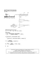
also provide the added benefit of a check for accuracy of readings. Figure 14 is an example of
the form used to record the readings.
Where plumb wires are being used, care should be taken to ensure there are no kinks in the wires.
With the weights installed, the entire length of each wire should be checked by feel for any bend
or kinks. If any kink can be felt, the wire should be replaced. While the wires don’t have to be
an equal distance from the shaft, they should be within ½ inch so that they are within the range of
the micrometer head. The brackets for the oil buckets should be sturdy and secure to prevent
spilling oil while taking readings. The weights should be heavy enough to keep the wires very
taut but not so heavy as to consistently break the plumb wires. The weights, when suspended in
the oil, should be completely submerged, but they should not touch the bottom or the sides of the
bucket. The steel banding material placed around the shaft at the reading elevations should be
level, and the distance from the coupling should be rechecked occasionally during the alignment
process to make sure it corresponds with the dimensions used for plotting.
4.2 Hamar Laser System
The Hamar laser system uses a laser beam to replace the wire and a micrometer adjustable target
attached directly to the shaft with a magnetic base to measure the distance from the shaft to the
laser (photo 4). There are two photoelectric cells mounted next to each other in the target with
opposite polarity. When the laser beam is perfectly centered between the two cells, the voltage
output of the target is zero. Four rigid steel bases are installed 90 degrees apart around the shaft
in the turbine pit corresponding to north, south, east and west. Magnetic bases on the laser attach
it to the steel bases and precision levels in the base of the laser act as the reference for plumb.
The laser must be moved and releveled for each set of readings (north, south, etc.). The readings
are recorded and the shaft centerline plotted in the same manner as with the wires.
The foremost problem encountered with the Hamar laser system is vibration from the mounting
baseplate. Any vibration of the baseplate will be transferred to the laser and be magnified as the
laser beam projects upward, making the top reading very unstable. Very solid base plates, rigidly
attached to the head cover or the turbine bearing bracket, limit the vibration transferred to the
laser. To prevent errors from the laser not being perfectly verical, the same end of the laser
should always be pointed toward the shaft. In this way, any error in verticality will be subtracted
out in the worksheet the same way as a taper in the shaft is corrected.
Another critical item to observe is the level. The laser must be leveled precisely initially and
rechecked frequently to obtain accurate measurements.
15
Unit Alignment Worksheet
Column
Column
Column 3
Column
Column
Column
Column
Column
1
2
4
5
6
7
8
Total
Actual
Mathematical
Column 1
Difference
½ Column 4
Direction
Total
Out of
Reading
amount to be
added to
Column 1 to
theoretically
move all wires
an equi-
distance from
center of shaft
plus
Column 2
N&S
E&W
(Out of Plumb
between top
and bottom
reading)
bottom of
shaft is out
of plumb.
(Direction
of smaller
number in
Column 3)
N+S
and
E+W
from
Column 3
Roundness
or
inaccuracy
of readings
(N+S)-
(E+W)
Should be
less than
0.002
First
Reading
Elevation
North 0.3445 0.0000 0.3445
0.0000
South 0.1505 0.1940 0.3445
East 0.1710 0.1735 0.3445
0.0000
West 0.2985 0.0460 0.3445
Second
Reading
Elevation
North 0.3425 0.0000 0.3425
0.0035 0.00175 N 0.6885
0.0000
South 0.1520 0.1940 0.3460
East 0.1710 0.1735 0.3445
0.0005 0.00025 W 0.6885
West 0.2980 0.0460 0.3440
Third
Reading
Elevation
North 0.3495 0.0000 0.3495
0.0080 0.0040 N 0.7070
0.0010
South 0.1635 0.1940 0.3575
East 0.1800 0.1735 0.3535
0.0010 0.0005 W 0.7060
West 0.3065 0.0460 0.3525
Fourth
Reading
Elevation
North 0.347 0.0000 0.3470
0.0120 0.0060 N 0.706
0.0005
South 0.1650 0.1940 0.3590
East 0.1805 0.1735 0.3540
0.0015 0.00075 W 0.7065
West 0.3065 0.0460 0.3525
1st Band
2nd Band
Centerline of
Coupling
3rd Band
4th Band
A
E
B
C
D
G
F
Thrust Runner
A = 170
B = 25
C = 40
D = 55
E = 80
Upper Wear Ring
F = 85
Lower Wear Ring
G = 25
Figure 14.—Unit alignment worksheet.
16