Advances in the Bonded Composite Repair o f Metallic Aircraft Structure phần 8 ppsx
Bạn đang xem bản rút gọn của tài liệu. Xem và tải ngay bản đầy đủ của tài liệu tại đây (1.31 MB, 51 trang )
390
Advances in
the
bonded composite repair of metallic aircraft structure
(assumed to apply for this specimen configuration):
(13.11)
Since, from Figure
13.12,
omax
is around
160
MPa and
a
is 33 mm,
Kcdt
is estimated
to
be
about
56
MPam'/2. Similar results for were obtained from several other
unpatched panels. These values for
I&
are in reasonable agreement with published
values for 2024T3 panels of this thickness.
For the patched panel, patching theory suggests that
K,
is approximately
53MPam1/*. Although
Ko0
is
fairly close to
Grit,
the former is an upper-bound
estimate of stress intensity
so
it is tentatively concluded that crack propagation in
the metal was not the cause of the failure.
Strain capacity analysis
A direct estimate, using joint theory, of
net strain
in the patch over the crack
indicates
a
value
of
7100
microstrain. However, if the extra load attracted to the
patch (as a result
of
the inclusion effect) is considered, the strain could be as high as
9500
microstrain. Since strain capacity of the boron/epoxy is measured to be about
7300
microstrain, the conclusion is that failure was probably a result of initial
failure of the patch.
Furthermore, as discussed in reference
[
11
for the patch configuration employed,
the ratio (inner-surface strain)/(outer-surface strain) in the patch is significantly
greater than unity. In this case it is estimated to be about
2.5.
On this basis the inner
strain could have exceeded
12
000 microstrain; however, the strain elevation would
be very localised.
The conclusion is thus reached that failure in the patched panels resulted from
initial failure of the patch, possibly associated with the strain concentration at its
inner surface.
This failure mode may change where significant disbond growth occurs during
fatigue cycling for two reasons:
0
Stress intensity
K,
may exceed
Lt
allowing the crack to grow catastrophically
0
The strain concentration in the patch over the crack will be reduced if even minor
Thus, for a small disbond, say a fewmm, residual strength is likely
to
increase
because
of
the reduced stress concentration in the patch.
Increasing the thickness of the patch, say to nine layers (the current patch is
seven layers), should provide some increase in residual strength. However, at higher
stress levels, plastic yielding of the metal around the patch (exacerbated by stress
concentrations at the ends of the patch) will limit this increase. The failure mode is
then expected to change from patch failure to disbonding from at the ends of the
patch.
under the patch.
disbonding occurs.
Chapter 13. Boronlepoxy patching efficiency studies 391
450
400
350
I
5
300
250
b
m
-
m
;
200
2
u)
150
100
50
0
I.,
-
:onstant
Amplitude a=% FALSTAFF a=39
mm
Fllla=38
mm
No
Fatigue a=30
mm
No
Fatigue a=33
mm
Standard Boron Standard Boron Standard Boron Unpatched
I
I
Standard Boron
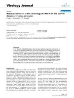
Fig. 13.13. Histogram showing residual strengths for patched panels with or without prior fatigue
testing and for an unpatched panel. The results for the panels with
no
prior fatigue are plotted
in
Figure 13.12.
Residual strength following fatigue testing
Tests were also conducted on panels after fatigue testing under (a) constant
amplitude,
(b)
F-1
11 spectrum loading-representative of the F-1 11 lower wing skin
or (c) FALSTAFF spectrum, representative
of
a standard fighter lower wing skin.
Figure 13.13 depicts the results together with those patched after fatigue
cracking. Thermographic NDI was used in an attempt to detect disbond damage
over the crack region in the fatigue-tested specimen; however, damage could only
be detected in the FALSTAFF specimen as a relatively small -2mm ellipse
centred on the crack. This does not imply that the other specimens had not suffered
damage, only that the disbonds were probably smaller or for some reason less
detectable by thermography.
The first conclusion is that the residual strength has not been reduced by cyclic
loading for cracks in the 30-40mm range. Indeed the strength may have actually
increased due to the reduction of stress concentration around the crack caused by
any local disbonding. In the case of the 56-mm crack residual strength was clearly
reduced compared to the others. Since this crack is approaching the boundary of
the patch, it is possible that in this case the critical stress intensity for the crack in
the panel was exceeded, rather than the failure stress of the boron/epoxy. In all test
panels the strength equalled or exceeded
oy
-
although, with no margin in the case
of the panel with the 56-mm crack.
As discussed later, there is a case for equating
oJ,
with DUL. If this case is
accepted it can be concluded that the patched panels had adequate residual strength
to satisfy most certification requirements.
392
Advances
in
the
bonded
composite repair
of
metallic aircraft structure
13.5.
An
approach to b/ep patch
design
13.5.1.
Cyclic
loading
Assuming that environmental degradation of the adhesive is not an issue
(through good quality control), the margin of safety, efficiency and durability of a
repair to a cracked component can be assessed from estimates of the following:
(a) The stress intensity range
AK
and
R
in the repaired region. This determines
patching efficiency through the crack-growth parameters
AR
and
nR.
(b) The tensile strain
eR
in the b/ep patch which allows estimation of the margin of
safety for failure of the patch. It is assumed for a composite patch that fatigue
is not an issue; if it were then the range of strain
AeR
and
R
ratio would have to
be considered.
(c) A (validated) damage parameter in the adhesive system (including the
composite interface). Possible parameters are the shear strain range
Ay
or
Mode
I1
energy release rate
AGII.
This allows estimation of the fatigue
durability
of
the adhesive system. It is best, if feasible, to design the repair
so
that the damage threshold of the adhesive system over the crack is not
exceeded; however, if it is not feasible the disbond growth rate, db/dN (Section
13.2.3) must be included in the analysis, using Eq.
(4).
Limited disbond growth
over the crack is acceptable, however, and within limits will not dramatically
reduce patching efficiency.
Another important factor needed for design of the repair system is the length
L*
available for the patch between obstructions (Figure 13.14), since this can limit the
allowable patch thickness. The length
LR
required for efficient load transfer
depends on the patch and adhesive parameters (Figure
13.3)
including patch
thickness
tp
and the taper rate at the outer ends of the patch.
Assuming largely elastic conditions in the adhesive (as required to avoid patch
system fatigue), a conservative estimate of the patch length
[l]
is given by:
6
LR
=
-
+
length of the taper
,
D
(13.12)
where
/3
is given by Eq. (Id), The taper rate for b/ep we use is around
3
mm per ply.
Finally, the residual stress
oT,
resulting from patch and component thermal
expansion mismatch, must be included in the analysis, since this influences
Ay,
eR
and
RR.
Residual stress
CT
depends on
AT=
(Toperating temperature
-
Tcure temperature),
typically
100
"C
for a
120
"C
curing adhesive and,
Aa
=
(@pat&
-
acomponent).
The
length between thermal expansion constraints in the component structure (see
Figure 13.13) influences
acomponent
which for full constraint is
0.5
aP.
Based on Rose's analysis described earlier, the author [l] developed a simple
algorithm for estimating the minimum thickness patch that could be applied within
the installation constraints that would survive the external cyclic loading.
It is generally desired to use the thinnest patch feasible for several reasons,
including (a) to minimise the residual stress problems, (b) to maintain aerodynamic
Chapter
13.
Boronlepoxy
patching
eficiency
studies
393
Patch
Craack
PARAMETERS
FIRST
CYCLE
FOR
MIN
THICKNESS
PATCH
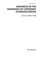
Fig.
13.14.
Outline
of
algorithm for
designing
the
minimum
thickness
patch.
acceptability, for example to minimise disturbance to the airflow when repairs are
made to an external surface, (c) to minimise balance problems; for example, when
repairs are made to a control surface, and (d) to comply with installation restraints,
for example, not to exceed available fastener lengths when fasteners must pass
through the patch for system requirements, or to maintain clearance between
moving surfaces.
The logic for the design approach is shown in flow chart form in Figure
13.14,
which is based on comparison of the following,
as
the patch is increased in
thickness one ply at a time:
0
The computed patch length
LR
with the allowable (available) length
L*
0
The computed styin in the patch compared with the experimentally determined
allowable strain
e,;
a value of
5000
microstrain was found to be reasonable for b/
eP.
0
The computed shear-strain range compared with experimentally determined
allowable
A?*
=
0.18
was originally used for FM73, but current work suggests
that
0.10
may be more appropriate for long life repairs.
These patch and adhesive allowables were obtained from tests on representative
bonded joints. Increasing patch thickness increases
LR
but reduces
eR
and
Ay.
Assuming constant amplitude fatigue at
Bo,
and
R,
Figure
13.15,
shows the
outcome
of
a calculation based on the parameters listed.
394
Advances in the bonded composite repair
of
metallic aircraft structure
~~138,
Rz0.1
2024T3
AT=IOO”C
FREE EDGES
L*
=
80 mm
25
mm
EXAMPLE
A?*.
~0.18
e*R=
5x1
O3
t.
=
0.1
9
mm
3 mm
-
7
plies
blep
eR
=
3x1
o3
ATA
~0.16
A
K,
=
12.5 MNm’”
A
K,
=
40 MNm’”
uT=67
MPa
LR=
57
mm
Fig.
13.15.
Outcome
of
an analysis for the minimum patch thickness,
AKa
is the stress intensity
for
the
unpatched case.
Once
AK,
is estimated the inspection interval
N
can be determined from
Eq.
(13.2) and (la) or (if disbonding is a consideration) from
Eq.
(13.4) as:
(13.13)
where
ai
is the initial crack size and
ax
is the size chosen for inspection. Typically
ax
would be less than one third patch width to provide at least three chances of finding
the crack before it grows out from under the patch.
As
shown in Figure 13.14, if the inspection interval is too short, (the
AK
reduction is inadequate) there is an option to increase the thickness of the patch
providing it can still fit within the allowable length.
13.5.2.
Spectrum
loading
Crack-growth analysis is significantly more complex under spectrum loading. It
is feasible to assess crack growth for the cracked component and damage growth in
the adhesive system
on
a cycle-by-cycle basis for the various values of effective
AKo,
and
R.
Chapter
13.
Boronlepoxy patching efJiciency studies
395
If the spectrum is unknown, design can be based on a standard spectrum:
FALSTAFF or TWIST for fighter or large transport aircraft respectively. If the
peak stress in the spectrum (the design limit stress,
CTDLL)
is unknown, an estimate
can be made based on the material yield stress
o,,
as described in the next section.
The patch length
LR
can then be estimated for the estimated patch thickness
t,,
to
obtain the required
K
reduction. However, this may be over-conservative since by
definition
DDLL
is expected to occur only once (although in fighter aircraft it can
occur many times) in the life of the aircraft. Thus
LR
could be based on say
0.5
or
0.6
CJDLL
-
and still provide acceptable residual strength at say 1.2
x
ODLL
(see final
section).
A simplified estimate of patching efficiency could be obtained by increasing
stresses in all cycles in the spectrum
above the threshold
for
crack growth
to the peak
stress
CJDLL.
As
this is a severe assumption for both the cracked component and
patch system, it provides an over-conservative estimate. A complication with using
this
approach is that the threshold stress will reduce with disbond growth.
13.5.2.1.
Estimating the design
limit
stress
(a) The most conservative is to equate it with material yield
o,,.
Thus the nominal
stress at the design ultimate load
DUL
is 1.50,,, which marginally exceeds the
material ultimate strength
ou.
For example for 2024T3 and 7075T6,
respectively,
ou/o,,
=
1.4 and 1.3.
(b) A less conservative but (in the author’s opinion) more reasonable assumption
[2] is to equate the stress at DUL with
o,,.
Thus in accord with the requirements
for DLL, where limited yielding is allowed at stress concentrations but no
large-scale yielding leading to permanent deformation.
As
an example, Table
13.1 provides
cDLL
and
o,,
values for the
F-1
1
1
lower wing skin, which is made
of aluminium alloy 2024 T581. This shows that the ratio
CT,,/ODLL
exceeds
1.5,
as required. Use of approach A would result in a
3040%
overdesign.
(c)
By
direct strain measurement, either from a static calibration or in flight.
(d) From a knowledge of the external aerodynamic loads and the availability of a
full F-E model of the aircraft and local region to estimate internal loads.
There are several options to estimate the
CDLL:
Table
13.1
Data
on
design limit stress
UDLL
for
F-111
for
several (DADTA) data points in the lower
wing made
of
aluminium alloy
2024 T581,
compared with the yield stress
uy
67 202.9
400.2 462.3
1.2 266.8 1.97
2.28
70
167.0 400.2
462.3
1.2 266.8 2.40
2.77
70a
204.2 400.2
462.3
1.2 266.8 1.96
2.26
78 149.7 400.2
462.3 1.2 266.8
2.67 3.09
154
171.8 400.2
462.3
1.2 266.8 2.33
2.69
194 165.6
400.2
462.3 1.2 266.8
2.42 2.79
396
Advances in the bonded composite repair of metallic aircraft structure
Approach (c) is very time consuming and likely to be prohibitively expensive in
most repairs. Approach (d) depends on having the loads and
F-E
model available,
and even then will be costly and time consuming. However, this is the preferred
approach for critical repairs and was the procedure adopted in a bonded composite
repair developed for the
F-1
1
1
lower wing skin [lo].
Of the two simple approaches the result of assuming approach (a) is that a thick
repair would be designed resulting, in the case of composite patches, in large
residual stresses and in large parasitic stress concentrations. This is not a major
concern for thin-skin components (skin thickness <2 mm) where approach (a) is
probably quite acceptable.
13.5.3.
Check on residual strength
It is most important to check that residual strength of the repaired region will
exceed
oDLL
by an acceptable factor
F
generally between 1.2 and
1.5
x
(the latter
being the design ultimate). If this is not the case the thickness of the patch will need
to be increased beyond that required for the fatigue stress level.
The residual strength
of
the patched cracked component appears to be dependent
on
the strain capability of the reinforcement (including strain concentration) and
the adhesive rather than on the stress intensity in the patched crack. However, a
first test should be made to check that at
F
x
ODLL,
KR
<
Ke
the effective critical
stress intensity for the cracked material. If this is not the case then the patch
thickness must be increased.
The main test check is to ensure that the patch static-strength allowables,
obtained from tests on representative bonded joints, are not exceeded. For the
adhesive the allowable shear strain will be greatly increased (for FM73,
Ay*
=
0.5);
however, the allowable patch strain
eR*
is unchanged, since for b/ep the static
strength allowable is the about same as the fatigue allowable.
At the ultimateload the adhesive yield shear stress will be greatly exceeded
so,
in
principle, a much longer length than predicted by
Eq.
(13.12) would
be
required.
However, since the ultimate load case is a check load (where large-scale yielding in
both the metallic structure and adhesive is acceptable, as long as failure does not
occur) the length given by
Eq.
(13.12) for the fatigue case should still provide an
adequate strength margin.
References
1.
Baker. A.A. (1988). Crack patching: Experimental studies, practical applications. Chapter 6 in
Bonded Repair of Aircraft Structures,
(A.A. Baker and R. Jones, eds.) Martinus Nijhoff, pp. 107-
173.
2.
Baker, A.A.
(1994).
Bonded composite repair
of
metallic aircraft components, Paper
1
in AGARD-
CP-550
Composite Repair
of
Military Aircraft Structures.
3. Rose, L.R.F.
(1988).
Theoretical analysis
of
crack patching. Chapter
5
in
Bonded Repair ofAircraft
Structures,
(A.A. Baker and R. Jones, eds.), Martinus Nijhoff, pp. 107-173.
Chapter 13.
Boronlepoxy patching efficiency studies
397
4.
Wang,
C.H.
and Rose.
L.R.F.
(1998). Bonded repair of cracks under mixed mode loading.
Int.
J.
of
5. Baker, A.A.
(1
993). Repair efficiency in fatigue-cracked panels reinforced with boron/epoxy patches.
6. Chalkley,
P.D.
and Baker, A.A. (1999). Development of a generic repair joint for certification of
7. Baker, A.A. and Chester,
R.J.
(1992). Minimum surface treatments for adhesively bonded repairs.
8. Baker, A.A. and Beninati,
0.
(1997) Repair efficiency in composite patched panels after removal of
9.
Baker, A.A. (1997). On the certification of bonded composite repairs to primary aircraft structure.
10.
Baker, A.A., Rose,
L.R.
and Walker,
K.F.
(1999). Repair substantiation for
a
bonded composite
Solids,
35,
pp. 2148-2113.
Fatigue and Fracture
of
Engineering Materials and Structures,
16,
pp. 753-765.
bonded composite repairs.
Int.
J.
Adhesion
and
Adhesives
19,
pp.
121-132.
Int.
J.
of’
Adhesives and Adhesion,
12,
pp.
13-18.
corrosion damage.
Proc.
of
Int.
Aerospace
Conf.
1997,
Sydney, Australia, pp. 53-60.
Proc.
of
ICCM
II,
Gold
Coast Australia, July, Volume 1, pp. 1-24.
repair to F-I11 lower wing skin,
Applied Composite Materials,
6,
pp. 251-267.
Chapter
14
GLARE PATCHING EFFICIENCY STUDIES
R.
FREDELL
and
C.
GUIJT
Department
of
Engineering Mechanics, Center for Aircraft Structural Life
Extension,
US
Air Force Academy
14.1
Introduction
Most bonded composite crack patching has been accomplished on small areas of
thick structures using high-modulus boron/epoxy composites. Extending the lives
of
aging transport fuselage structures, however, may involve repairs to large areas
of thin fuselage skins and lap joints. These structures often see their highest
mechanical stresses (due to pressurization) at the low temperatures encountered at
cruise altitude. Hence, more attention to the thermal properties of composite
materials may be needed when fuselage structures are being repaired.
This chapter presents the results of detailed parametric studies of thermal effects
on bonded repairs to cracked pressurized transport fuselage structures. The hybrid
glass/epoxy/ aluminum materials known as
GLARE
are offered as an alternative to
boron/epoxy for this special crack patching application. Experiments performed at
room temperature, and at the low temperatures encountered at high altitudes, show
that bonded
GLARE
2
patches can out-perform boron-epoxy in selected repairs to
thin skins. These results are discussed with the conclusion that, under certain
circumstances, thermal compatibility can be the driving factor in repair material
selection in pressurized fuselage skin repairs.
14.1.1.
Overview and background of jibre metal laminates
The Fiber metal laminate
(FML) GLARE
2
is a hybrid material
of
moderate
modulus, combining 2024-T3 aluminum with high-strength unidirectional S-glass/
epoxy composite in
a
sheet like laminate [2-31. It is known for its excellent fatigue
resistance due to the “crack-bridging” effect of the fibers and its high residual
399
Baker,
A.A
Rose,
L.R.F.
and Jones,
R.
(eds.),
Advances
in
the Bonded Composite Repairs of Metallic Aircraft Structure
Published
by
Elsevier
Science
Ltd.
Advances in
the
bonded
composite
repair
of
nietallic
uireraft struetirre
atuminfum
alloy
Fig. 14.1. Schematic
of
glass/epoxy/aluminum laminate
GLARE
2.
strength. Figure 14.1 shows a schematic of GLARE 2 with a crack in the aluminum
layers and "crack-bridging'' fibers.
GLARE and the ARALL family of FMLs were developed by Delft University,
the Netherlands, with the support of AKZO and Alcoa. FMLs have the high
strength and excellent fatigue resistance of advanced composite materials, while
retaining the machinability and cold-formability of aluminum alloys. In addition,
the GLARE laminates approach the performance of titanium alloys as fire barrier
materials. Fiber metal laminates are in service on the C-17 Globemaster I11 (aft
cargo door), Boeing 777 (cargo floors and liners) aircraft, and as bonded repairs on
a USAF C-5A. Airbus Industrie will use GLARE as a fuselage skin material for the
A-380 aircraft.
14.2.
Parametric studies
of
various patch materials
When one focuses on pressurized fuselage skin repairs, the following special
conditions must be considered:
0
The damaged structure is relatively thin (up to
2
mm/0.079"). An extremely stiff
patch is not required, or even desireable, as load attraction to the repaired region
could cause secondary damage to the relatively thin skin.
0
The adhesive is cured at a temperature ranging from 80 to 120 "C (180 to 250 OF),
and the fuselage sees service temperatures ranging from perhaps
60
"C (140 OF)
Chapter 14.
GLARE
patching
efficiency
studies
40
1
(unloaded, hot day on the ground) to
-54°C
(-65°F)
(maximum internal
pressure, temperature at cruise altitude). This increases the likelihood of thermal
mismatch problems.
Because the transport fuselage experiences its greatest internal pressure loads at its
minimum service temperature, thermally-induced stresses in a fuselage bonded
repair can be a more significant consideration than in, say, a fighter wing skin
repair.
Reduction in stress intensity factor,
K,
to slow or stop crack growth, is not the
only design criterion for effective crack patching. The significant variables to be
considered in a crack patching design include (see Figure
14.2):
0
slow down or stop crack growth
0
acceptably low stresses in the patch to avoid patch failure
0
avoidance of excessively high stresses in the skin adjacent to the repair
to
0
tolerably low peel and shear stresses in the bond line
0
prevention
of
adhesive bond line shear yielding to ensure patch and bondline
By
varying the patch material and dimensions, the adhesive, and the curing
temperature, the repair designer may be able to produce a patch meeting all of these
preclude new fatigue problems in the skin
durability
\
Ob
\me
\
Ob
0@
0
8
8
0
0
0
8
oo
Patch strength
8QQ
Patch
durability
8 8
0 0
@
1
creep
anchor
80
088001
00
eooooo
1
oe0ooo
@@
00
88
Fig.
14.2.
Failure modes
for
bonded repairs.
402
Advances in
the
bonded composite repair
of
metallic aircraft structure
10
goals for successful patching. However, in an operational maintenance environ-
ment, the design and analysis
of
bonded repairs must be able
to
be accomplished
quickly, often without a detailed knowledge of the precise stress state in the cracked
panel.
This section describes the results of detailed parametric studies performed
on
various repair designs based on the Rose model
of
crack patching
[&8].
It considers
an infinite, center-cracked, isotropic plate loaded by a remote biaxial stress with a
bonded orthotropic elliptical patch on one side of the plate. Several writers have
published studies comparing various finite element-based crack patching models
[9-111 with the Rose model.
Tarn and Shek [9] performed a detailed finite element analysis to compare the
crack-bridging efficiency predicted by various elastic models of boron/epoxy patch
repair of cracked aluminum sheets. Material responses were assumed to be linear
elastic, and thermal effects were ignored.
With increased loading, inelastic material behavior is first observed
in
the
adhesive layer. Therefore,
to
consider linearly elastic material behavior only, the
adhesive in the Rose model was given an artificially high shear yield strength.
In
the
elastic case shown in Figure
14.3,
the reduction in K of Rose (shown as the
“CalcuRep” result) matches well with the more complex finite element models from
the literature. The maximum difference between Rose and [9] occurred when the
repair patch was eight plies thick. Here Rose overestimated the
K reduction by no
more than
5%.
The assumption of various authors that the adhesive will behave elastically
is
questionable, especially when the patch extensional stiffness is roughly equal with
Fig.
14.3.
Comparison
of
reduction in stress intensity factor for bonded boron/epoxy patches, elastic
and elastic-plastic models
of
adhesive behavior.
Chapter
14.
GLARE
patching efficiency studies
403
the cracked plate stiffness. Thin patches experience large normal strains over the
crack and induce large shear strains in the adhesive as well.
The lowest line in Figure
14.3
represents the Rose model’s results when elastic-
plastic adhesive behavior was allowed around the crack tip. The differences
between the models are striking. With the elastic model, adhesive shear stresses are
able to reach unrealistically high levels
so
thin patches appear to be quite effective
at reducing
K.
However, including inelastic material effects in the model shows that
when patch thicknesses are relatively low, the reduction in
K
is not nearly as
significant. This is due to the patch strains being quite high, which can lead to early
adhesive yielding and delamination, reducing crack-patching effectiveness. There-
fore, it can be said that a realistic constitutive model of the adhesive is important,
since the avoidance of large-scale adhesive yielding can be important for effective
crack patching and good patch durability.
This result is consistent with the work of Marissen
[
121 and Roebroeks
[
131,
who
found that low fiber/metal ratios (Le. low patch/plate stiffness ratios) resulted in
poor crack-bridging efficiency for fiber metal laminates. The elastic results converge
with the elastic-plastic model only when six boron plies are used. At this point, the
extensional stiffness
of
the boron patch approaches that of the plate.
These results allowed sufficient confidence in Rose’s basic approach to proceed
with the parametric analysis, outlined in the following section. The study assesses
the thermal considerations to be accounted for in the selection of patch materials.
Crack patching
of
aircraft usually involves local heating of the repair area.
During the curing process, the unheated structure surrounding the repair area
constrains the thermal expansion
of
the heated area. But the patch, which
is
entirely
inside the heated region, expands freely. In stiffened structures, the “effective”
coefficient of thermal expansion (CTE) of the constrained structure is much less
than the material CTE. Figure
14.4
illustrates this effect.
After cooling to room temperature, the bondline for patch materials with
relatively low CTE, like boron- or carbon-fiber composites,
is
relatively stress free.
This has been pointed out by various writers
[7,11,14-161.
Moderate-
to
high-CTE
patches actually place the crack in compression at room temperature. This reduces
the stress intensity near the crack tip and decreases or even stops crack growth.
Figure
14.5
shows the effect of cooling to room temperature for high-
and
low-CTE
materials, respectively.
The blue arrows indicate the compressive stress
in
the skin acting on the crack.
The additional tensile stress in the patch is less significant if composite patch
materials are used with a higher fatigue threshold.
When a transport aircraft climbs to cruising altitude, its fuselage is cooled
uniformly to the outside air temperature
(-54
“C at
10
km). The structure cools and
contracts uniformly, but a low thermal expansion composite patch would not
contract nearly as much.
For example, a boron-epoxy patch shrinks only about
1/6
as much
as
the now-
unconstrained aluminum fuselage. This induces an additional cyclic tensile (crack-
opening) load on the crack tip at a time when the pressure-induced stress is highest.
Further, the adhesive that was ductile and relatively flexible at room temperature is
404
Advances
in
the bonded composite repair
of
metallic aircraft structure
High CTE patch (e.g.,
GLARE)
Low
CTE patch (e.g., boron-epoxy)
Fig.
14.4.
Thermal effects in skin and patch, due to the elevated temperature during bonding.
High CTE patch (e.g.,
GLARE)
Low
CTE patch (e.g., boron-epoxy)
Fig.
14.5.
Thermal effects in skin and patch at
room
temperature.
substantially stiffer and more brittle at
-54
"C.
The additional tensile load due to
these effects occurs every flight. On the other hand, a patch material with a moderate
or high
CTE,
such as GLARE
2
will still cause some crack-closing compression in
the skin. (GLARE
2
has a CTE of approximately two-thirds that of aluminum.)
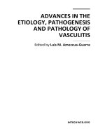
Figure
14.6
compares the patching efficiency of two potential fuselage patch
materials, boron-epoxy and GLARE@
2.
The patching efficiency is defined as the
reduction of the stress intensity factor,
K,
at the crack tip. A sufficient reduction
of
these stresses will slow down or even stop further crack growth. The stresses near
Chapter
14.
GLARE
patching
ef$ciency
studies
405
120 AI 2024-T3
hoop
=
IOOMPa Glare 2
dong
=
5OMpa
Thermal
effect
2a
=
51mm
Altitude
=
IOOOOm
.
110
E
100
No
thermal
\
Boron
Y
go
I
A-
?I-
.*
.
-
-A-
A
Glare
U
**
Thermal
effects
I2
80
0'
_*
0
0.5
1
1.5
2
2.5
patch thickness
[mm]
Fig.
14.6.
Comparison of reduction in
stress
intensity factor for bonded
GLARE
2
and boron patches,
with
and without considering thermal effects
[5].
the crack tip are described with the stress intensity factor
K.
A 100% reduction in
K
means no crack opening. Higher than 100% means that the crack is still in
compression at the given load due to the residual thermal stresses.
The comparison shown, using the Rose-model, was done for the case of a
narrow-body fuselage at a cruising altitude of 10 km. In the 2024-T3 Aluminum
skin of 1 mm thickness, a crack
of
51
mm is modeled. The patch dimensions were
the same for both materials. The patch length (perpendicular to the crack) was
140mm, the patch width was 102mm. To bond the patch over the crack, the
adhesive AF-163-2K of 3M was used. The Shear Modulus,
G,
and the Yield
Strength,
Tyield,
of
this material (modeled as elastic-perfectly plastic material) were
corrected for the cruising temperature. The manufacturer-recommended cure
temperature of 120
"C
was used.
A
biaxial stress field of 100 MPa (hoop tension)
and
50
MPa (longitudinal tension) was applied.
When thermal effects are ignored, the much stiffer boron/epoxy patch seems to
do
a better job closing the crack. However, when the complexities of constraint
during bonding, and free thermal contraction during cruise flight are considered,
GLARE
2 is predicted to be the more effective patch. At an often used stiffness
ratio
(Epatch
*
tpatch
/
Eskin
*
&kin)
of roughly one, the thickness of the Glare patch
is
1.1 mm and the thickness for boron is
0.39
mm. The K-reduction is 100% for Glare
and
78%
for boron.
Thermal effects also change the situation with regard to skin stresses at the edge
of the patch: Any thermal residual
K
reduction at the crack tip, gained by using a
high-CTE patch, occurs at the expense of additional tension in the skin at the patch
tip. The designer/analyst must strike the proper balance.
406
Advances in the bonded composite repair
of
metallic aircraft structure
The choice of adhesive cure temperature can also affect the results. When repairs
are performed
on or near structures containing absorbed moisture (e.g. honeycomb
core materials), cure temperatures under
100
“C
are desired to prevent damage
from evolved steam. Furthermore, a lower cure temperature can reduce thermal
buckling problems. Moreover, cure temperatures are limited
by
equipment
capabilities, which in turn are driven by the size, material(s), structure, and
substructure (which can act as an effective heat sink) of the repair area.
When materials of different coefficients of thermal expansion are bonded, cure
temperature can affect residual stress states as well. Baker
[17]
recommends curing
at “the lowest possible temperature” to minimize residual thermal stresses.
If
a
patch has a higher effective coefficient of thermal expansion than the substrate,
cooling from the cure temperature results in residual compression at the crack tip.
As
pointed out before, this should
by itself be beneficial for fatigue crack
retardation.
If
the patch’s effective thermal expansion coefficient is lower than the
substrate’s,
a
residual tensile (crack-opening) load will exist at the crack tip.
However, the change in cure cycle could (adversely) affect the adhesive properties.
Figure
14.7
shows the effect of various cure temperatures on the patching
effectiveness of
GLARE
2
and boron/epoxy patches in the Rose model at the cruise
altitude situation described before. In the analyzed case, the effective expansion
coefficient of the stiffened fuselage structure is approximately equal to that of
boron/epoxy during the cure cycle of the adhesive (local heating). Thus, in fuselage
skin repairs, boron/epoxy is not substantially affected by a change in the cure
temperature. The large thermal effects with boron/epoxy occur in the cooling from
room
to
cruise temperature of the complete structure,
now
the
CTE
of the structure
AI
2024-T3
105
t=
1.05rnm
Altitude
=
10000
rn
75
“;I
100
-
c
95
Y
5
90
c
I
a
2
85
V
Glare
2
Boron
70
1
I
0
20
40
60
80
100
120
Cure Temperature
[‘C]
Fig.
14.7.
Influence of adhesive cure temperature
on
patch effectiveness.
Chapter 14.
GLARE
patching
efjciency
studies
407
0.07
1
I
0.06
-
0.05
-
0.04
-
9
%
E
Jz
0.03
~
0.02
-
?-
0.01
.
0-
3
plies,
t=0.38rnrn
Boron
.
yield12
I
-0.01
0
20
40
60
80 100
120
Cure Temperature
["C]
Fig.
14.8.
Influence
of
adhesive
cure
temperature
on
maximum adhesive shear
strain
is higher since there is no local constraint and will be roughly equal to the CTE
of
aluminum.
Thermal effects have yet another significant impact on patch selection. The high
adhesive shear strains experienced with some low CTE patches cannot be reduced
significantly by curing at a lower temperature,
as
shown in Figure 14.8, generated
using the Rose model under the same conditions as before.
With GLARE@ 2, the effect is reversed due to the higher CTE of the patch
during the cure cycle: A cure temperature of 100 to 120°C actually benefits the
bond by reducing adhesive shear strains at low operating temperatures.
Furthermore, as can be seen in this figure, the global adhesive shear strains with
the boron/epoxy patch remain above half the adhesive yield strain. Half the yield
strain is a design limit for typical operating loads. Because
of
both effects
mentioned, the bonded GLARE 2 patch repair will have
a
better durability. Also, a
higher resistance against delamination might be expected.
A
series of analyses were performed using the same narrow-body fuselage case at
various cruise altitudes corresponding to different operating temperatures.
Figure
14.9
shows the influence of the operating (cruise) temperature on the four
significant crack patching design parameters. Again, the shear modulus and yield
strength of the adhesive were corrected for the various temperatures.
The boron/epoxy patch is strongly influenced by the warmer temperatures at
lower altitudes, while the more thermally compatible GLARE
2
patch is less
sensitive to temperature variations. The skin stresses adjacent to the boron/epoxy
patches were consistently lower.
408
Advances
in
the
bonded composite repair
of
metallic aircraft
strueiure
Influence
of
cruise temperature on
Adhesive Shear Strain
-60
-50
-40
-30
-20
-10
0
10
20
Cruise Temperature
[‘C]
Influence
of
cruise temperature on
maximum stress in the skin
210
-
200
Glare
2
(t=0.85mm)
.,
g
190”
z
180
140
7301:::
.’,:
-60
-50
-40
-30
-20
-10
0
10
20
Cruise Temperature
[‘C]
Influence
of
cruise temperature on
Patch Effectiveness
Influence
of
cruise temperature on
maximum
stress
in the patch
1053
400
,
100
Glare
2
(t=0.85mm)
.
C
$
250
f
Glare
2
(t=0.85)
-
E
95
5 90
U
150
75.
:
: : :
100
.
: :
.
:
:
:
-60
-50
-40
-30
-20
-10
0
10
20
-60
-50
-40
-30
-20
-10
0
10
20
Cruise Temperature
[“C]
Cruise Temperature [“C]
Fig.
14.9.
Influence
of
cruise temperature
on
crack-patching design parameters.
14.3.
Experimental results
Experimental results tended to bear out the analytical predictions: Both
constant- and variable-amplitude fatigue testing was performed at room- and
low-temperature conditions
[
181.
In experiments with single-sided bonded repairs to pre-cracked thin aluminum
sheets,
GLARE
2
patches always gave longer lives than equivalent (in terms of
patch stiffness) boron/epoxy repairs. The largest difference was in the time to crack
growth re-initiation after repair, see Figure
14.10.
The aluminum panels were pre-
cracked to 25 mm at different stress levels;
60,
80,
and
120
MPa. After the patches
were applied the fatigue tests were continued at 120MPa, and
t~,,,j~/c~,,,~
=
R
=
0.05.
These experiments were performed to investigate the effect
of the pre-crack level and the plastic zone
on
crack-growth rates after patching. The
fact that the crack growth rates after patching are lower for the Glare patches
indicates a lower K-repaired, just as predicted by the Rose-model. At a pre-crack
level of 120MPa, the plastic zone formed stops crack growth for roughly 250000
cycles after the Glare patch was applied, obviously AK
is
low enough to stop the
crack from growing through the plastic zone immediately. The scatter in this period
can be very large. Periods of
50000
up to
400000
cycles of no crack-growth are
observed in similar specimens
[
191.
Chapter
14.
GLARE
patching efficiency studies
409
Pre-crack tests
0
50000
I00000
150000
200000 250000
300000
350000 400000
Number
of
cycles
N
Fig.
14.10.
Effect
of
pre-crack stress level and plastic zone on crack growth behavior after patching.
Previous research [1] has indicated that the 120 "C cure cycle temperature is the
dominant mechanism in determining the retardation period. Baker found that the
cure cycle of the adhesive does affect the plastic zone created in the material before
patching. These recent experiments appear to indicate that the CTE match between
patch and substrate is another important feature in retardation of crack growth
after patching.
In other experiments, the influence of overloads in variable amplitude fatigue
testing of repairs was observed to be muted in comparison to unrepaired fatigue
crack growth experience. An example of this behavior is given in Figure 14.11.
Overload experiments with patches specimens showed the classical fatigue
behavior, an overload slows down the crack growth due to the plastic zone formed
during the overload. The effect
is
smaller than with unpatched-cracked panels since
the
K
is lower due to the patch. When testing different spectra, see Figure 14.1
1,
this behavior was confirmed. The spectra used were derived from Lockheed stress
data for the C-5A, see Chapter
3
1. The unfiltered spectrum contained all the loads,
the filtered spectrum had less loads and allowed shorter testing times. The crack
growth under the patch was the same for both spectra, however, the crack-growth
rate of an unpatched crack was different for the filtered and the unfiltered spectra.
This indicates again that some load cycles are less significant if a patched crack is
410
Advances in the bonded composite repair
of
metallic aircruft structure
Spectrum test results
60
-
Filtered spectrum unpatched (01)
70
*O
t
lo/
0
patched
t
Filtered spectrun
S3
patched
t
Full spectrum
06
unpatched
+Filtered
spectrun
01 unpatched
I
0
10
20
30
40
50 60
70
80
Number of
blocks
Fig.
14.11.
Effect
of
spectrum
loads.
tested. If all failure modes, for example a crack at the patch tip due to (high) skin
stresses, are considered, the (filtered) spectrum must be used which results in the
same unpatched crack growth rate.
At low temperatures, a mismatch in CTE between the patch and the skin can
cause higher stresses in both the adhesive and at the crack tip. However,
experiments show a surprising result. In Figure
14.12
the results of crack-growth
experiments are shown for boron and Glare patches at -40°C. At the lower
temperatures, the crack-growth rates for both patch materials are lower. There are
two possible explanations for this behaviour:
1.
Although the residual thermal stresses might be higher, the low temperature
increases the shear modulus,
G,
of the adhesive. This can reduce crack opening
and therefore reduce the crack-growth rate.
2.
Aluminum has slower crack growth rates at low temperatures due to the lower
humidity at the low temperatures. This explains the fact that both Glare and
boron perform better at lower temperatures despite the increased thermal
stresses.
14.4.
Discussion
The analytical and experimental results clearly show the strong influence of the
differential CTE effects on the stress intensity reduction and subsequent crack
Chapter
14.
GLARE
patching ef$ciency studies
41
1
Low
temperature tests
0
50000
100000
150000
200000
250000
300000
Number
of
cycles
N
Fig.
14.12.
Effect
of
low
temperatures on crack-growth rates
of
patched panels.
growth. When the thermal effects are considered, boron/epoxy patches are less
effective than the fiber metal laminate GLARE
2
at operating temperatures below
the cure temperature of the adhesive.
Furthermore, the effect
of
the cure temperature can have a significant positive
influence on the effectiveness of the GLARE
2
patch, while the boron/epoxy patch
is only slightly influenced (Figure
14.7).
In Figure
14.8,
one can see the positive
influence of an increasing cure temperature on the decreasing shear strain in the
GLARE
2
patch, while the strains in the bond line of the boron/epoxy patch
remain above the design limit for typical operating loads.
Figure
14.9
shows the influence
of
the operating temperature on the most
significant crack patching design parameters. More thermally compatible
composite patches are less sensitive to temperature variations. This results in
better patching effectiveness at high- altitude/low-temperature cruise conditions,
while keeping the adhesive shear strain in the bond line acceptably low. However,
better crack closure comes at the expense of higher skin stresses at the edges of the
repair. This increases risk of a new fatigue crack nucleating at the boundary of the
patch, and must be considered in design.
The experiments show the same trends as predicted by the Rose-model: A closer
CTE-match between the patch and the skin can result in more efficient patches for
412
Advances in the bonded composite repair
of
metallic aircraft structure
a typical fuselage skin thickness
(1
mm). Both the pre-crack stress level and the
patch material used affect the re-initiation period of the crack after patching. If the
same stress level is applied before and after patching, the Glare patches can result in
significant retardation periods. This retardation period is not affected by the cure-
cycle of the adhesive.
Overloads and spectrum loading does affect crack growth under patches in the
same way as it does for unpatched cracks. However, the absolute effect is smaller
due to the reduced
K
after patching. When testing bonded repairs under spectrum
loading, the spectrum has to be verified on unpatched cracks.
The low temperature tests show that although the thermal stresses might
increase, the crack-growth rate decreases. This is not what the models predict,
therefore the change in crack-growth behavior
of
aluminium at low temperatures/
humidities must be more dominant than the increase in thermal stresses under the
repair.
A
higher
G
of the adhesive, might also contribute to the slower crack-
growth rates.
This combination of analyses and experiments tends to indicate various niches
where various candidate crack patching materials appear to be best suited. The
high-modulus, low-CTE boron/epoxy composite excels in the repair of relatively
thick cracked structures where peak flight loads are encountered at moderate
to
high service temperatures. In these cases, low patch volume could be critical for
aerodynamic reasons, and
CTE
mismatch-related problems are minimal. Good
examples
of
boron/epoxy applications include lower wing skins, wing/fuselage
attachments, and fuselage keels beams.
In contrast, the moderate-modulus. high-CTE GLARE
2
patches appear to be
best suited for repair of thin fuselage skins. The high stresses in these structures due
to the maximum pressure level at low cruise temperature are increased by the
additional temperature-related stresses. In repairs to thin-skinned fuselage
structures, the slightly greater patch thickness associated with GLARE
2
is usually
negligible. With the superior reductions in
K
and accompanying low adhesive shear
strains, GLARE
2
patches promise superior durability, resistance against
delamination, and excellent damage tolerance.
14.5.
Summary and conclusions
The results
of
more than
20
years of experience with repairs of relatively thick
cracked aircraft structures have shown boron/epoxy to be an excellent patch
material. Peak flight loads at moderate to high service temperatures can be
sustained by the high-modulus material, without demanding high patch volumes
(thickness). Because of the thick structures, mismatch problems due to the curing
temperature are minimal.
When the transition is made to the repair of cracked fuselage structures, thermal
considerations become paramount. The fuselage will see its highest stress levels at
low temperatures.
Chapter 14.
GLARE patching ejficiency studies
41 3
Detailed parametric studies were performed to calculate thermal effects.
Variation
of
the patch thickness, cure temperature and cruising temperature for
two competing patch materials, the fiber metal laminate
GLARE@
2
and the
traditional composite boron/epoxy, gave a good opportunity to compare those
materials for
a
fuselage crack patching situation.
Experimental work was performed in constant- and variable-amplitude fatigue a
room and low temperatures. The results showed several advantages of
GLARE
2
over boron/epoxy patches in fuselage skin repairs due to improved thermal
expansion compatibility between
GLARE
2
and aluminum. The results predict
GLARE
2
to be an effective, damage-tolerant fuselage repair material.
References
I.
Baker, A.A. and Jones. R. (1988). Bonded Repair of Aircraft Structures (A.A. Baker and R. Jones.
eds.). Boston: Martinus Nijhoff Publishers.
2. Fredell, R. and Gunnink, J. (1992). Fiber metal laminates for improved structural integrity.
Proc.
o/-
the Int. Workshop
on
Structural Integrity
of
Ageing Aircraft,
Atlanta. Georgia, April, pp. 362-375.
3.
Fredell, R., Vlot, A. and Roebroeks, R. (1994). Fiber metal laminates: New frontiers in damage
tolerance.
Proc.
qf
the 15th Int. European Conference
of
the Society for the Advancement
qf‘
Material
and Process Engineering.
Toulouse, France, June, pp.
3
19-328.
4.
Fredell,
R.
(1994). Damage Tolerant Repair Techniques for Pressurized Aircraft Fuselages. WL-TR-
94-3 134, Wright-Patterson Air Force Base Ohio, June.
5.
Fredell, R., van Barneveld, W. and Vlot, A. (1994). Analysis of composite crack patching of fuselage
structures: High patch elastic modulus isn’t the whole
story.
Proc.
qf
the
39th
hf.
SAMPE
Symposium and Exhibition,
Anaheim, California, April,
pp.
610-623.
6. Rose, L.R.F.
(1981).
An application of the inclusion analogy.
Int.
J.
S0lid.s and Structures.
17.
7. Rose, L.R.F. (1988). Theoretical Analysis of Crack Patching, in Bonded Repair of Aircraft
8.
Muki, R. and Sternberg,
E.
Int.
J.
Solids and Structures,
4,
pp.
75-94.
9. Tarn, J.Q. and Shek,
K.L.
(1991). Analysis
of
cracked plates with a bonded patch.
Enginwring
10.
Chu. R.C. and
KO,
T.C.
(1989). Isoparametric shear spring element applied
to
crack patching and
11.
Jones,
R.
and Callinan, R.J. (1980).
J.
Structural Mechanics,
8(2), pp. 143-149.
12.
Marissen, R. Fatigue Crack Growth in ARALL, Ph.D. thesis, Department of Aerospace
Engineering, Delft University
of
Technology, Delft, the Netherlands,
13.
Roebroeks, G.H.J.J. (1991). Towards GLARE The Development of a Fatigue Insensitive and
Damage Tolerant Material, Ph.D. thesis, Department of Aerospace Engineering, Delft University
of
Technology, Delft, the Netherlands, December.
14.
Rose,
L.R.F. (1988). Residual Thermal Stresses, in Bonded Repair of Aircraft Structures (Baker.
Jones, eds.). Dordrecht: Kluwer Academic Publishers, pp. 90-91.
15.
Baker, A.A., Davis, M.J. and Hawkes, G.A. (1979)
Proc. 10th Int. Symp.
qf’the
Int.
Comm.
on
Aeronautical Fatigue,
paper
4.3.
16.
Rose, L.R.F. (1982).
Int.
J.
Fracture,
18,
pp.
135-144.
17. Baker, A.A. (1988). Crack Patching: Experimental Studies, Practical Applications, from Bonded
Repair
of
Aircraft Structures (Baker, Jones, eds.). Dordrecht: Kluwer Academic Publishers, pp.
107
172.
pp. 827-838.
Structures, (Baker, Jones, eds.). Dordrecht: Kluwer Academic Publishers, pp. 77-106.
Fracture Mechunics,
40(6),
pp.
1055-1065.
instability.
Theoretical and Applied Fracture Mechanics,
11, pp. 93-102.
414
Advances
in
the bonded
composite
repair
of
metallic
aircraft
structure
18.
Verhoeven,
S.
(1988). In Service Effects on Crack
Growth
Under Bonded Composite Repairs.
Masters thesis, Department of Aerospace Engineering, Delft
University
of Technology, Delft, the
Netherlands, July.
19.
Guijt,
C.
and Fredell,
R.
(1996). Delamination Effects in Fuselage Crack Patching,
SAMPE
Anaheim.