Advances in the Bonded Composite Repair o f Metallic Aircraft Structure phần 4 docx
Bạn đang xem bản rút gọn của tài liệu. Xem và tải ngay bản đầy đủ của tài liệu tại đây (1.43 MB, 57 trang )
144
Advances in the bonded composite repair
of
metallic aircrafi structure
with a step change in stiffness from
~ptp/(
1
-
v’,)
to
Eptp/(
1
-
v’,)
+
ERtR/(
1
-
vi)
over a central potion
ly(
5
B
-
b,
as indicated in Figure 7.4(e), with
b
given by
(7.13)
This equivalence will be exploited in Section 7.4 to assess the redistribution of stress
due to
a
bonded reinforcement.
The prospective stress in the plate directly underneath the reinforcing strip,
00
=
op(x
=
0),
can be readily determined by integrating Eq. (7.4),
1
1
b
=
-
tanh
j?B-
(BB<
1)
B
“P
’
with
S
denoting the stiffness ratio given below,
(7.14)
(7.15)
which is an important non-dimensional parameter characterising
a
repair.
As
will
be shown in the following section the actual prospective stress
00
is
somewhat
higher than that given by Eq. (7.14). This under-estimation is primarily due to the
ignorance of the “load attraction” effect in a 2D plate associated with reinforcing.
7.4.
Symmetric repairs
We return to the solution of the problem formulated in Section 7.2, assuming
that the repaired structure is supported against out-of-plane bending or the cracked
plate is repaired with two patched bonded on the two sides. The analysis will be
divided into two stages as indicated in Section 7.2.
7.4.1.
Stage
I:
Inclusion analogy
Consider first the re-distribution of stress in an
uncracked plate
due to the local
stiffening produced by the bonded reinforcement.
As
illustrated in Figure 7.2(a),
the reinforced region will attract more load due to the increased stiffness, leading to
a higher prospective stress than that given by Eq. (7.14). The 1D theory of bonded
joints (Section 7.3) provides an estimate of the load-transfer length
j?-’
for load
transfer from the plate to the reinforcement. If that transfer length is much less
than the in-plane dimensions
A,
B
of the reinforcement, we may view the reinforced
region as an inclusion of higher stiffness than the surrounding plate, and proceed in
the following three steps.
1. Determine the elastic constants of the equivalent inclusion in terms
of
those of
2.
Determine the stress in the equivalent inclusion.
the plate and the reinforcing patch.
Chapter
7.
Analytical
methodsfor
designing composite repairs
I45
3. Determine how the load which is transmitted through the inclusion is shared
between the plate and the reinforcement, from which the prospective stress
00
can be calculated.
Step
(2)
is greatly facilitated by the known results of ellipsoidal inclusions [3]: the
stress and strain within an ellipsoidal inclusion is uniform. as indicated
schematically in Figure 7.2(a). The uniform stress state can be determined
analytically with the help of imaginary cutting, straining and welding operations.
The results are derived in
[SI
for the case where both the plate and the reinforcing
patch are taken to be orthotropic, with their principal axes parallel to the
s
-
y
axes. We shall not repeat here the intermediate details of the analysis but simply
recall the results for the particular case where both the plate and the reinforcement
are isotropic and have the same Poisson's ratio,
vp
=
VR
=
v.
The prospective stress
in the plate along
y
=
0 within the reinforced region
(1x1
I
A)
is
60
=
&T=
~
(7.16)
where
(7.17)
BA
4~-
4+2-+2-+S
Z
'[
A B
with
2
=
3(
1
+
S)2
+
2(
1
+
S)(B/A
+
A/B
+
vS)
+
1
-
v2S2
(7.18)
It
is clear that the stress-reduction factor
4
depends on three non-dimensional
parameters: (i) the stiffness ratio
S,
(ii) the aspect ratio
B/A,
(iii) the applied stress
biaxiality
i
The parameters characterising the adhesive layer do not affect
00,
but
we recall that the idealisation used to derive Eq. (7.17) relies on
B-'
<
A,
B,
and
p-'
is of course dependent on adhesive parameters.
To illustrate the important features
of
Eq.
(7.17), we show in Figure 73a) the
variation
of
the stress-reduction factor
4
with aspect ratio for two loading
configurations: (i) uniaxial tension
(i
=
0),
and (ii) equal biaxial tension
corresponding to pure shear
(A
=
-l),
setting
S
=
1
and
v
=
1/3 for both cases.
It can be seen that there is little variation for aspects ratio ranging from
B/A
=
0
(horizontal strip) to
B/A
=
1 (circular patch),
so
that for preliminary design
calculations, one can conveniently assume the patch to be circular, to reduce the
number of independent parameters. It is also noted from Eq.
(7.17)
that for
v
=
1/3
and a circular patch
(A/B
=
I),
the stress-reduction factor
cp
becomes independent
of the biaxiality ratio
A.
As
illustrated in Figure 7.5(a) the curves for
1
=
0
and
;L
=
-1
cross over for
B/A
=
1,
indicating that, for a circular patch, the transverse
stress
gFX
does not contribute to the prospective stress,
so
that this parameter can
also be ignored in preliminary design estimates. In this particular case, the stress-
reduction factor
4
depends on the stiffness ratio
S
only, as depicted in Figure
7.5(b), together with the first-order approximation given by Eq.
(7.14).
It can be
seen that the first-order solution ignoring the load attraction effect of composite
146
Advances in the bonded composite repair
of
metallic aircraft structure
Uniaxial tension(X=
0)
Pure shear(X=-1)
0.9
".
.
0
0.2
0.4
0.6
0.8
Aspect ratio of patch
B/(A+B)
(a)
1
.o
0.9
0.8
0.7
8
0.6
2
0.5
2
0.4
2
0.3
0.2
0.1
0
a
-
o
Exactsolution
-
+= (1+0.277S-O.O712S2)/(l+S)
-
-
-&=
1/(1+S)
1
.o
0
0.5
1
.o
1.5
2.0
Stiffness ratio
S
(b)
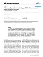
Fig.
7.5.
Variation of reduced stress with (a) aspect ratio for an elliptical patch of serni-axes
A
and
B
under uniaxial tension and biaxial tension equivalent to pure shear;
(b)
stiffness ratio
S
for a circular
patch.
patch overestimates the reduction in plate stress. An improved solution can be
obtained by constructing an interpolating function based on the exact solution,
,
(7.19)
1
+
0.277s
-
0.0712S2
l+s
$=
which is shown by solid curve in Figure 7.5(b), indicating a very good fit to the
exact solution.
The inclusion analogy also gives, as a natural by-product, the stress in the plate
outside the reinforced region. The stress at the point
x
=
0,
y
=
B+ is
of particular
interest, because this stress represents the increased stress due to the so-called load
Chapter
7.
Analytical methods for designing composite repairs
147
attraction effect; a load attraction factor
QL
can be defined as the ratio of the plate
stress just outside the patch to the remote applied stress
(7.20)
It is clear from Figure 7.5(a) that for the case of a balanced patch
(S
=
1) under
uniaxial tension, this load attraction factor ranges between
1
for patch of infinite
width to 2 for patch of zero width. For the typical case of circular patch, the load
attraction factor is approximately 1.2.
7.4.2.
Stage
11:
Stress intensity factor
Once the stress at the prospective crack location is known, one can proceed to the
second stage of the analysis in which the plate is cut along the line segment
(1x1
5
a, y
=
0),
and a pressure equal to
go
is applied internally to the faces of this
cut to make these faces stress-free. Provided that the load transfer to the
reinforcement during this second stage takes place in the immediate neighbourhood
of the crack, the reinforcement may be assumed to be of infinite extent. Thus the
problem at this stage is to determine the stress intensity factor
K,
for the
configuration shown in Figure 7.3(a).
Without the reinforcement, the stress-intensity factor would have the value
KO
given by the well-known formula,
KO
=
~ofi
(7.21)
This provides an upper bound for
K,,
since the restraining action of the patch
would reduce the stress-intensity factor. However,
KO
increases indefinitely as the
crack length increases, whereas the crucial property of the reinforced plate of
Figure 7.3(a) is that
K,
does not increase beyond a limiting value, denoted by
K,,
as will be confirmed later. That limiting value is the value of the stress intensity
factor for a semi-infinite crack. It can be determined by deriving first the
corresponding strain-energy release rate as follows. Before we proceed, let
us
first
determine the deformation of the reinforced strips shown in Figure 7.3(b). The
adhesive shear stress
ZA
is governed by the differential Eq. (7.9), which has the
following solution for the particular case of semi-infinite strip,
~A(Y)
=
ZA,rnaxe-’.’
,
(7.22)
where
rmax
can be determined from the simple equilibrium condition,
QOtf
=
so“
ZA
(YPY,
ZA,max
=
P~P~o
(7.23)
Recalling
Eq.
(7.4), the opening displacement of the plate at
y
=
0
can be readily
148
Advances in the bonded composite repair
of
metallic aircraft structure
determined,
(7.24)
Let us denote the total opening as
6
=
224,. The above equation can be rewritten as,
with
(7.25)
(7.26)
Consider the configuration shown in Figure 7.6. If the semi-infinite crack extends by
a distance da, the stress and displacement fields are simply shifted to the right by da.
The change in the strain energy
UE
is
that involved in converting a strip of width da
from the state shown as section
AA'
in Figure 7.6 to that shown in section
BB',
as
depicted in Figure 7.7. Consequently the change in the potential energy for a
crack advancement ha, which
is
defined as the difference between the strain energy
change
UE
(=
1/2ootp6) and the work performed by the external load
W
(=
GotpJ),
1
n=uE-w= rJ
OtPd
The crack extension force, Le. the strain-energy release rate
G,
is given by
which can be re-written as, recalling Eq. (7.25),
+Z
A
A
B
B4
B'
B'+
*
A'
A'
Fig
7
6
A
patched crack subjected to internal pressure
(7.27)
(7.28)
(7.29)
Chapter
7.
Analytical methods for designing composite repairs
149
6
s
(a)
(b)
Fig.
7.7.
Illustration
of
the interpretation
of
G,
as a complementary energy. (a) Elastic adhesive and
(b)
elastic-plastic adhesive.
From the above equation, assuming that the usual relation holds between the strain-
energy release rate
G
and the stress-intensity factor
K
[22], we obtain,
00
K
"-&
(7.30)
It is clear from this derivation that
K,
is an upper-bound for
K,.
The validity of this
formula will be substantiated by an independent finite element analysis to be
discussed later.
7.4.3.
Plastic adhesive
The stress-intensity factor solution derived in the previous section is valid only if
the adhesive remains elastic. If the maximum adhesive shear stress does exceed the
shear yield-stress, the relationship between
00
and the crack-opening displacement
6
will become non-linear, as illustrated in Figure 7.7(b), which also shows the
correct area corresponding to
G,.
For an adhesive that is elastic-perfectly plastic
with a shear yield-stress
zy,
the adhesive begins to yield at the following stress,
ZY
boy
=
-
BtP
(7.31)
It can be shown that for
00
2
boy
the crack opening-displacement
6
is given by,
ZYtA
1
+
~
=-
PA
[
(;y)2]
=E
[I
+
($))*I
>
(00
2
boy)
(7.32)
Following the method outlined in the previous section, the strain-energy release
rate
G,
can be determined,
s
00
Y
60
G,
=
o06
-
/bods
=
/
6doo
+
/
6doo
=
kEp
[
cri
P3+3P-1
3p2
]
'
(7.33)
0
0
00
Y
150
Advances in the bonded contposite repair of metallic aircraft structure
1.4
4
\
hi
1.3
8
'I
1.2
d
b
*
."
A
D
1.1
2
LI
0
CI
1.0
where
c0
p=-
00
Y
Then, the stress-intensity factor for
P
2
1
can be expressed as
(7.34)
(7.35)
where
K,,el
denotes the value which would be obtained from
Eq.
(7.30)
for the
stress
a0
ignoring the plastic yielding in the adhesive. As can
be
seen from
Eq.
(7.35),
the increase in
Km
due to adhesive yielding depends only on the
plasticity ratio
P
defined by
Eq.
(7.34),
as shown in Figure
7.8.
7.4.4. Finite
crack
size
Adhesive plasticity
ratio
P
Fig.
7.8.
Increase in stress-intensity factor due to adhesive yielding.
Chapter
7.
Analytical methods for designing composite repairs
151
h
g
1.00
5
3
>.I
)
.3
2
0.75
s
E
C
.3
(I)
rn
Y
0.50
.e
C
0
0
S
-m
.e
Y
2
0.25
0.01
Nomalised
crack
length
ku
Fig.
7.9.
Reduction in stress-intensity factor
for
various patch configurations. Symbols denote the exact
solutions by the
Keer
method, solid curves denote the interpolating function, and dashed curve denotes
the solution
of
crack bridging model.
reduction factor Fdepends strongly on the parameter
k
given by
Eq.
(7.26)
and to
a
lesser extent on the stiffness ratio
S,
as shown by the symbols in Figure
7.9.
Based
on the solutions of the integral equation
[
141,
the following interpolating function
can be constructed,
112
F(ku)
=
[nLu
-
tanh (1
:zku)]
’
(7.37)
where constant
B
has been determined by curve fitting the numerical solution of the
integral equation, which gives
B
=
0.3 for balanced repairs (S
=
1
.O)
and
B
=
0.1
for infinitely-rigid patch
(S
+
a).
A
simple yet more versatile method of determining the reduction in stress-
intensity factor after repair is the crack bridging model [lo], which has been
recently extended to analyse the coupled in-plane stretching and out-of-plane
bending of one-sided repairs [17]. From the previous analysis it is clear that the
essential reinforcing action at the second stage is the restraint on the crack opening
by the bonded reinforcements. The basic idea underlying the crack bridging model
is that this restraining action can be represented by a continuous distribution of
springs acting between the crack faces, as illustrated in Figure 7.10. This
idealisation reduces the problem at stage
TI
to two parts: (i) determine the
appropriate constitutive relation (i.e. stress-displacement relation) for the springs,
and (ii) solve a one-dimensional integral equation for the crack opening,
6(x)
=
ulr(x,y
+
Of)
-
.,’(x,y
+
0-)
=
2u;(x,y
+
O+),
1x1
5
a
(7.38)
0.1
1
It is assumed that distributed linear springs act between the crack faces over the
152
Advances in the bonded composite repair of metallic aircraft structure
go
t
tt
t
tt
ttt
tl
X
Fig.
7.10.
Schematic representation
of
a
centre-crack reinforced by distributec jprings.
crack region
so
that the boundary conditions on
y
=
0
are
u,,(x)
=
0,
1x1
2
a
,
(7.39b)
where
k
denotes
a
normalised spring constant
which has dimension
length-’.
It is
worth noting that this normalised spring constant
k
has already been determined in
Section 7.4.2 and is given by Eq. (7.26). With these boundary conditions, the
problem of determining the crack opening displacement
u,(x)
can be reduced to
that of solving the following integral equation
[lo,
171,
(7.40)
The integral in the above equation is interpreted
as
a Hadamard finite part [24],
which can be viewed as the derivative
a
Cauchy principal value integral. The above
equation can be efficiently solved using either Galerkin’s method or collocation
methods. Once the crack-opening displacement
uJx)
is determined, the stress-
intensity factor
K,
can be calculated by
(7.41)
Detailed numerical results for
K,
are available in reference [lo], which also
provided the following interpolating function constructed based on the numerical
Chapter
I.
Analytical methods
for
designing composite repairs
,
patch
-
adhesive
,plate
(b)
Fig. 7.11. Finite element mesh (a) quarter model and
(b)
mesh near crack tip.
results,
1
+
2.23ka
1
+
4.776ka
+
7(k~)~
F(ka)
=
153
(7.42)
154
Advances in the bonded composite repair of metallic aircraft structure
0.06
I
D
-
-E)
FE
ITSUI~S
s-
1.0
1
k
=
0.096
mm-'
0'
-0.45-0.30-0.15
0
0.15
0.30
0.45
Normalii
coordinate
zltp
(a)
0
0.03
*
0.02
w
s
-
1.0
k
=
O.096mm'
o
FEmults
-
Equation
(36)
Equation
(40)
30
60
90
120
Crack
length
a
(mm)
(b)
Fig. 7.12. Comparison between finite element solution and analytical predictions.
which is shown in Figure 7.12(a).
As
compared to the exact solutions by the Keer
formulation
(Eq.
7.37), the crack-bridging model (Eq. 7.42) slightly over-estimates
the reduction in stress-intensity factor for balanced repair
(S=
1) in the short crack
limit. Both the two interpolating formulas,
Eqs.
(7.37) and (7.42) recover the
asymptotic solution of
Eq.
(30) in the long crack limit as
a
+
co.
7.4.5.
Finite element validation
To
substantiate the theoretical solutions obtained
so
far, an extensive finite
element analysis has been performed for various crack lengths [12]. Due to
symmetry only a quadrant
of
the repair shown in Figure 7.l(a) was modelled.
No
Chapter
7.
Analytical methods for designing composite repairs
I55
Table
7.
I
Dimensions and material properties
of
a typical repair.
Young’s
modulus
Thickness
Layer (GW Poisson’s ratio (mm)
Plate
71
0.3 3.0
Reinforcement
207
0.3
1
.O
Adhesive
1.89
0.3
0.2
debond between the plate and reinforcement or adhesive plasticity was considered.
The finite element mesh near the crack tip region is shown in Figure 7.1 1. All three
constituents, the patch, the adhesive, and the plate are assumed to deform
elastically only, and are each modelled by 20-noded isoparametric brick elements.
The dimensions and material properties of the repair configuration being
considered are summarised in Table 7.1. For this repair, we have the shear stress
transfer length
b-’
=
5.634 mm, and the normalised spring constant
k
=
0.096 mm-’
.
From the finite element results, the stress-intensity factor is
calculated using Eq. (7.41), with
Ep
being replaced by the plane-strain value
Figure 7.12(a) shows a comparison between the theoretical estimate and the finite
element results for a long crack
(kaz
lo),
indicating an excellent agreement within
the mean stress-intensity factor through the plate thickness. It is also clear that the
stress-intensity factor at the outer surface away from the adhesive layer is
somewhat higher than near the adhesive layer. The asymptotic behaviour of the
stress-intensity factor is shown in Figure 7.12(b) together with the two analytical
estimates (37) and (42). The crack-bridging solution seems to slightly over-estimate
the repair efficiency.
Ep/(
1
-
v2).
7.5.
Shear
mode
Although cracks that are likely to be encountered in practice are generally
aligned in a direction perpendicular to the principal tensile stress (or strain), giving
rise to mode
I
cracking, there are at least two circumstances where mixed mode
cracking is a major concern in the context of bonded repairs. Firstly, application
of
bonded reinforcements, which are frequently anisotropic, may alter the local stress-
state near the crack region
so
that the maximum principal stress may no longer
remain perpendicular to the crack plane. Secondly, structures are frequently
subjected to non-proportional loading in which the principal stress-strain axes
rotate with time, thus cracks may experience a time-dependent mixed mode
loading.
If
the bonded repair technique is used to repair mode
I1
cracks. one
important question that needs consideration is the effectiveness of repairs.
For simplicity let
us
consider the particular case of an isotropic circular patch
(A/B
=
I)
with a Poisson’s ratio
v
=
1/3.
In this case, the prospective stress
in
the
plate after repair can be determined using the general solution for biaxial tension
156
Advances in the bonded romposite repair
of
metallic
aircraft struriure
presented in Section 7.4.1, namely
Eq.
(7.19),
1
+
0.2773
-
0.0712S2
70
=
r"
1
l+S
(7.43)
Detailed solution of the stress-intensity factor
K,
for shear loading can be found in
[14]. We shall not repeat here the intermediate details of the analysis but simply
recall the results for the upper-bound and the interpolating function. The upper-
bound solution
of
Kr
is
given by an equation similar to that for tensile mode,
where the
normalised
shear
spring
constant
kI1
is given by
AS
2(1
+S)(1
+v)
'
kII
=
with
(7.44)
(7.45)
(7.46)
It is evident that
kII
is lower than the spring constant pertinent to mode
I.
For
instance, in the case
of
isotropic patch
kI1
is related to the spring constant
kI
for
mode
I
crack,
(7.47)
For finite crack size, the stress-intensity factor
Kr
can also be expressed as [14]
with
F(x)
being given by
Eq.
(7.37) or
Eq.
(7.42).
An important implication arising from the difference in the spring constants is
that when strongly anisotropic reinforcements with low in-plane shear modulus,
such as unidirectional plastic reinforced composites, are used to repair a crack
under shear loading (with the fibres being perpendicular to the crack), the repair
efficiency will be much lower than that could be expected on the basis of mode I
analysis. It should of course be mentioned that under remote shear loading, the
crack would be aligned perpendicular to the maximum tensile stress, hence aligning
the fibres perpendicular to the crack
is
still the optimal configuration.
Chapter
7.
Analytical methods for designing
composite
repairs
157
7.6.
One-sided
repairs
So
far we have ignored the tendency for out-of-plane bending that would result
from bonding a reinforcing patch to only one face of an un-supported plate,
so
that, strictly speaking, the preceding analysis is more appropriate for the case of
two-sided reinforcement, with patches bonded to both faces, or one-sided repairs to
fully supported structures. For the case of un-supported one-sided repairs, it
is
again convenient to divide the analysis into two stages. In Section 6.1 the stress
reduction due to stage
I
will be anaiysed within the framework of geometrically
linear elasticity
[
121, whereas
a
geometrically non-linear analysis
[
171 will be
presented in Section 7.6.2. These two solutions will provide an upper and lower
bound to the actual stress distribution. In both cases the geometrically linear
analysis is all that needed for stage
11.
For stage I we shall consider the particular
case where the reinforcement covers the entire cracked plate, ignoring the load
attraction effect.
7.6.
I.
Geometrically linear analysis
Consider first the effect of one-sided reinforcement on an
un-cracked
plate which
is subjected to a uniaxial tension. Assuming that the reinforcement is far greater
than the shear stress transfer length, we treat the reinforced region as a composite
plate with a rigid bondline. The stress distribution in the plate and the
reinforcement can be determined using the conventional theory of cylindrical
bending of plates, i.e. we shall assume that the bending deformation of the
reinforced portion satisfies the usual kinetic condition that plane sections remain
plane. The position of the neutral plane of the composite plate consisting of the
base plate and rigidly-bonded reinforcement is denoted by
F,
referring to Figure
7.13,
(7.49)
The moment of inertia of the reinforced region
Zl
is
zI
=
zp
+
z~E;/E;
,
(7.50)
where
E’
refers to the plane-strain Young’s modulus
(E’
=
E/(
1
-
v2)),
and
zp
=
4/12
+
tpP
,
(7.51)
The stress distribution in the patched plate is assumed to be linear in the thickness
direction,
so
that it can be specified in terms of the membrane force
NO
and a
bending moment
Mo
per unit length in the x-direction, as depicted in Figure 7.13
158
Advances in the bonded composite repair
of
merallic aircraft structure
neutral axis
of
c
composite section
(b)
Fig. 7.13. Stress distribution in an un-cracked plate reinforced with a patch
(a)
composite plate
subjected to uniaxial tension; (b) stress distribution in the plate.
(see
[12,17]
for more details),
Ptp
rJmt;9
1+s+I,
’
No
=
oyY(y
=
0,z)dzE
-
4P/2
IP
I2
rJ*
t;2
Mo
=
-
1
ay,,(y
=
0,z)zdzE
-
121,
(7.53)
(7.54)
Comparison between Eqs.
(7.14)
and
(7.53)
clearly shows that the plate in a one-
sided repair is transferring more membrane stress than in an equivalent two-sided
repairs. Therefore, due to out-of-plane bending induced by load eccentricity, the
stress distribution along the prospective crack path before the crack appears is
higher than for
a
corresponding two-sided reinforcement. In addition, there is
a
bending moment acting on the prospective crack faces. Consequently, due to the
shift
of
neutral plane, one-sided repairs would experience not only an increase in
the net force that the plate is transmitting, but also
a
secondary bending moment;
both contributing to a considerable increase in stress-intensity factor.
In stage
11,
analysis of the crack-tip deformation requires the use of the shear
deformation theory, which yields that the stress intensity factor varies linearly
through the plate thickness,
Chapter
I.
Analytical methods for designing composite repairs
159
No
(b)
Fig.
7.14.
(a) Single strap joint representing one-sided repairs subjected to membrane tension and
bending moment, and (b) notations and boundary conditions.
where
K,,,,
and
Kb
denote respectively the membrane and bending stress intensity
factors. The strain-energy release rate can be determined following the method
outlined in Section
7.4.2,
except that the change in the potential energy now
consists of two terms: work done by the membrane force and the bending moment
[12],
referring to Figure
7.14,
tpG:
=
Nouo
+
MoOo
,
(7.56)
where the superscript
"*
"
refers to the strain-energy release rate for one-sided
repair, and
uo
and
190
denote the opening displacement and the angle of rotation of
the crack faces, which are related to the membrane force
NO
and
MO
via the
following relation
[
171,
(7.57)
160
Advances in the bonded composite repair
of
metallic aircraft structure
with
Egt;
Dp
=-
12
'
Therefore the total strain-energy release rate can be expressed
as
*1
tP
G,
=
-
[CIIN;
+
(Ci2
+
~21)NoMo
+
C22M;]
which can be simplified to become
*
(o"o)2
02
G,
=-
(1+q2
'
(7.61)
(7.62)
(7.63)
(7.64)
(7.65)
(7.66)
where
k
is given
by
Eq.
(7.26), and the term
o
is well approximated
by
the following
expression [12],
Chapter
7.
Anal.vtica1
method7
for
designing
composite
repairs
161
0.3,
. ~~.
~~.
.~~
0.2
0.1
R
-
-
~
c1
FE
results
(PAFEC)
I
Two-sided repair
"0
50
100
150
200
Half
crack length
a
(mm)
Fig.
7.15.
Comparison between analytical solution and finite element results for one-sided repairs.
Symbols denote the results of three-dimensional finite element analysis and the curves indicate the
theoretical formulas.
Consequently the root-mean-square stress-intensity factor
K3c,rms
for one-sided
repair can be expressed as,
It
is
now possible to define a spring constant for one-sided repairs,
(7.68)
(7.69)
With this spring constant, the stress intensity factor
for
a one-sided repair can
be
expressed in a similar form as for two-sided repairs,
6"
1+s
Kms(u)
=
-&Fi(k*a)
,
(7.70)
where
F,
is given by Eq.
(7.37).
Figure 7.15 shows a comparison between
Eq.
(7.70)
and the results of
3D
finite element analyses. The repair configuration being
considered is the same as that analysed in Section
7.4.4.
The same problem has been
analysed using two different finite element codes, namely
ABAUQS
[26]
and
PAFEC
[25];
both yielded approximately the same result. It can be seen that the
above formula is in good correlation with the finite element results. It is also worth
noting that the results confirm that the stress-intensity factor
Krms
for a one-sided
repair
is
much higher than that for an equivalent two-sided repair, indicating the
importance of out-of-plane bending.
162
Advances
in
the bonded composite repair of metallic aircraft structure
+
Fig.
7.16.
A
plate with a through crack reinforced with tension and bending springs.
The root-mean-square stress-intensity factor
Kms
is related to the membrane and
bending stress intensity factors
[12],
(7.71)
Although the root-mean-square of the stress intensity factor has been derived, the
maximum and minimum stress intensity factors still remain unresolved. It is
apparent that the energy method alone is insufficient determine the membrane and
bending stress intensity factors, as an additional equation is required to partition
K,,
into membrane and bending components. To this end, let us now briefly
discuss a crack-bridging model which
is
capable of analysing the combined tensile
stretching and bending of one-sided repairs.
7.6.2.
Crack bridging model
The perturbation problem of stage I1 for a one-sided repair can be reduced by
representing the patch by distributed springs bridging the crack faces
[
171, as
illustrated in Figure 7.16. The springs have both tension and bending resistances;
their stiffness constants are determined from a
ID
analysis for a single strap joint,
representative of the load transfer from the cracked plate to the bonded patch. The
spring constants are given by Eq. (7.57). For the purpose of parametric
investigation, we introduce the following non-dimensional variables,
1
6
,
h2(x)
=
-etp/a
hl(X)
=
-
U
(7.72)
Chapter
I.
Analytical methods for designing composite repairs
163
By using Reissner’s plate theory, the normalised crack face displacement
hl
and
normalised crack face rotation
h2
are solutions of the following coupled integral
equations
[
171,
1
NO
-
1
dq
+
(ktta)hl (r)
+
(ktba)h2(r)
=
-
,
2x
Jm
EP
tP
-I
(7.73a)
where
(7.76)
with
KO
and
K2
are the modified Bessel functions of the second kind. The integral
equations can be readily solved by expanding the unknowns using Chebyshev
polynomials of the second kind. The membrane and bending stress intensity factors
K,
and
Kb
are directly related to the values of
hl
and
h2
at
q
+
1.
With the prospective membrane force
NO
and bending moment
MO
are given by
Eqs. (7.53) and (7.54), respectively, the membrane and bending stress intensity
factors can be solved. For the repair configuration specified by Table 7.1, the results
are shown in Figure 7.17 together with the finite element results. Considering the
approximate nature of the crack bridging model and the finite element method, the
reasonably good correlation between the predictions and the finite element results
confirms the validity of the above theoretical model.
7.6.3.
Geometrically non-linear
analysis
The geometrically linear analysis presented in the preceding section is strictly
speaking applicable only when the out-of-plane deflection is negligible relative to
plate thickness, i.e. when the applied stress
om
is very low. Otherwise the
geometrically non-linear deformation, as indicated in Figure 7.18, has to be taken
164
Advances in the bonded composite repair
of
metallic aircraft structure
Fig.
7.17.
Theoretical predictions and finite element results for a typical one-sided repair assuming
geometrically linear deformation.
t"
s
-
U
___.__
^
U
zf
y;
.r/
:+B44 l.~;
Fig.
7.18.
Geometrically non-linear deformation of a single strap joint representing one-sided repairs.
into account. We shall use the rigid-bond approximation and denote the deflection
of
the plate as
w.
The governing equation for the deflection
of
the beam inside and
outside the repaired region is,
EpIt
-
=
~"Otp(w
+
2)
,
d2
w
IyI
5
B
,
(7.77a)
dY2
d2
w
EpZp-
=
Ptpw
,
a
5
JyI
5
B+
L
,
(7.77b)
where
It
and
Ip
are given by
Eqs.
(7.50) and (7.51) respectively. The boundary
condition is
dY2
w(y
=
B+
L)
=
0
(7.78)
The general solution of the deflection
w
is
(7.79)
w={
C1coshp+C2sinhp-z
(Iyl
<B)
,
C3
cash
xPy
+
C4
sinh
xPy
(a
5
Iyl
I
B
+
L)
,
Chapter
7.
Analytical methods for designing composite repairs
165
where
(7.80)
and constants
C1,
CZ,
C3,
and
C,
can be determined from the boundary condition
(78) and the following continuity and symmetry conditions,
.C(y
=
0)
=
0
,
(7.81)
W(Y
=
B-)
=
~(y
=
B+)
(7.82)
d(y
=
B-)
=
W’(Y
=
B+) (7.83)
After some derivation the following constants are determined,
-
z
-
r:
tanhz B-tanhxp(B+L)] tanhXB
’
1
~,[I-qanh~~Btanh~,(B+L)]
CI
=
c2=0
1
xsinh~Btanhx,(B+
L)
c3
=
-C1
xp
cosh xpB[l
-
tanh
xpB
tanh xp(B
+
L)]
’
c3
c4
=
-
tanh
xp
(B
+
L)
(7.84a)
(7.84b)
(7.84~)
(7.84d)
The deflection at the centre of the reinforcement is given by
M’(Y
=
0)
=
CI
-
z
(7.85)
The above solution has been verified for a particular strap-joint representing the
one-sided repair specified in Table 7.1. In the finite element analysis, the lengths B
and
L
are taken to be
80
and
200
mm. The results for the deflection at the centre of
the joint
y
=
0
are shown in Figure 7.19(a) together with the analytical prediction
(85),
indicating the accuracy of the beam theory solution. Similarly the finite
element results for the deflection along the joint and Jhe analytical solution are
shown in Figure 7.19(b), together with the analytical solution (79), indicating a
good agreement. From the above analytical solution it is clear that the
displacement
w
at the centre of the strap joint
w
depends on three non-dimensional
parameters,
xB,
xp/x,
and
LIB.
It is easy to show that
w
approaches
-2
as
xpB
+
x,
provided
LIBZO.
This limiting case corresponds to when the neutral
axis
of
the patched region is aligned perfectly with the path of the applied load.
166
Advances in the bonded composite repair of metallic aircrafi structure
Normalised
overlap length
ZB
0
-
3
9
ns
O-i.
e
-
-
-
FE
results (non-linear)
.7
Analytical solution
li
0
100
200
300
400
Applied stress
om
(MPa)
(a)
t
- -
-
FE
solution (non-linear)
.
~
Analytical solution
-1.2'
"
'
"
' ' '
"
' '
"
'
0
loo
200
300
Coordinate
y
(mm)
(b)
Fig.
7.19.
Deflection
of
a one-sided strap joint accounting
for
geometrically non-linear: deformation:
(a)
centre
of
overlap, and
(b)
along the joint.
Since the bending moment at the centre
of
the
overlap
is
M(y
=
0)
=
C,Ptp
,
(7.86)
the prospective membrane force and bending moment can now be determined,
No
=
A40
=
omtp c,a-t$z
1+s+
It
7
(7.87a)
(7.87b)
Chapter
I.
Analytical methods for designing composite repairs
167
With the prospective force and bending moment given by Eqs. (7.87), the coupled
Eqs.
(7.73) can then be solved numerically. The superposition principle used in the
previous section to reduce the problem of a one-sided repair subjected to remote
tension to a simple perturbation problem where the crack is internally pressurised
is, strictly speaking, not valid should the structure undergo geometrically nonlinear
deformation. However, an upper bound solution can be obtained by a hybrid
method, in which the prospective stress distribution is solved using geometrically
nonlinear elasticity theory, the stage
I1
analysis is carried out using the
geometrically linear theory, i.e. the crack bridging method developed in Section
7.5.2.
A
proof that this hybrid method will provide a conservative prediction of the
stress intensity factors can be found in [17]; a validation using the geometrically
non-linear finite element method will be presented later.
For a given repair configuration, the prospective membrane force
(Eq.
(87a))
increases with the load
P
while the bending moment (Eq. (87b)) decreases,
resulting in a net increase in the stress intensity factors, although the rate of
increase is slower than that expected from geometrical linear considerations. This is
illustrated in Figure 7.20(a) for the case of half crack length
a
of 20mm. It is seen
that the minimum stress-intensity factor
&in
determined by the hybrid method
correlates very well with the finite element results. However the hybrid method
over-predicts the maximum stress-intensity factor,
Kmax,
confirming that the hybrid
method is an upper-bound solution [17]. A similar trend can be observed in
Figure 7.20(b) which shows the asymptotic behaviour of the stress-intensity factors
as the crack length increases. The remote applied stress
oJ:
is kept to be
400
MPa.
Again the minimum stress-intensity factor
Kmin
determined by the hybrid method
correlates very well with the finite element results, whereas the maximum stress-
intensity factor
Kmax
determined by the hybrid method is greater than that obtained
from finite element analysis.
7.7.
Residual thermal
stress
due
to
adhesive curing
The process of adhesive bonding using high-strength structural adhesives
(thermal-plastics) generally requires curing the adhesive above the ambient
temperature. For instance, in a typical repair applied to aircraft structures the
reinforced region is initially heated to a temperature of
120
"C,
under pressure, for
approximately one hour (the precise curing cycle depends on the adhesive being
used). Upon cooling the fully cured, patched structure to the ambient temperature,
thermal stress will inevitably develop in both the plate and the reinforcement, due
to cooling a locally stiffened structure, especially when the reinforcing patch has a
lower coefficient of thermal expansion than the plate being repaired. Thermal
stresses may also arise when the patch structure experiences thermal cycling in
service. Therefore thermal residual stresses represent a major concern to the repair
efficiency of a repair. This is because the resulting thermal residual stresses post
cure in the metal plate are inevitably tensile, owing to the increase in the stiffness of
the patched region and the lower coefficient of thermal expansion of the composite
168
Advances
in
the
bonded
composite repair of metaIlic uircraft structure
ili
2l
rn
n
Geometrically
,I
linear solution
,
'
\,
.,,/
u
i,
0
100
200
300
400
Applied stress
nm
(MPa)
(a)
<
e4
4
High
crack
length a (mm)
(b)
Fig.
7.20.
Geometrically non-linear deformation of a single strap joint representing one-sided repairs.
patches. This tensile residual stress will increase the maximum stress-intensity
factor of the crack after repair, hence may enhance fatigue crack growth rate (see
Chapters 11 and 12).
7.7.1.
Temperature distribution
Solutions of the thermal residual stresses in symmetric repairs and one-sided
repairs have been developed in
[
181 and
[
191, respectively. In the following, only the
results pertaining to symmetric repairs will be presented; details of solution for one-
sided repairs can be found in reference [19]. Consider the configuration shown in
Figure 7.21(a), in which an isotropic plate is reinforced by a circular patch of radius
Ri.
The coordinate system
xy
is chosen
so
that the principal axes of the orthotropic