Tunable lasers handbook phần 10 ppt
Bạn đang xem bản rút gọn của tài liệu. Xem và tải ngay bản đầy đủ của tài liệu tại đây (1.36 MB, 52 trang )
434
Paul
Zorabedian
1
.OVNertical
Div
500~s/Horizontal
Div
b
-
1330.0 1325.0 1320.0
Equivalent Wavelength
(nm)
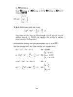
FIGURE
5
1
Swept-wavelength measurements of AOTF transmittance characteristics: (a)
Crys-
tal Technology filter driven at 88.5
MHz.
(b)
Matsushita filter driven at 68.54
MHz.
(Reproduced
with permission from Zorabedian [46].
0
1995
IEEE.)
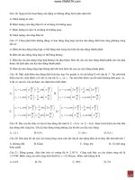
Dichroic
prism pair
FIGURE
5
2
Grating-tuned extended-cavity laser containing a quasi-phase-matched KTP wave-
guide
for
intracavity frequency doubling. (Reproduced with permission from Risk
et
a1
[162] and
the American Institute of Physics.)
crystal can be placed inside an
ECL
to take advantage of the higher circulating
intracavity power and the wavelength control provided by the tuning element.
Intracavity second harmonic generation has been performed in grating
ECLs
using angle-phase-matched a-iodic acid (HIO,) bulk crystals
[
1611 and quasi-
phase-matched, periodically poled waveguides in KTP substrates
[
1621 (Fig.
52).
Ten milliwatts of 532-nm light has been generated from a Nd:YVO, laser inter-
nally doubled with a KTP crystal and pumped with
55
mW from an interference-
filter-controlled quasi-degenerate
ECL
at
809
nm
[
1631 (Fig. 53).
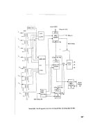
8
Tunable External-Cavity Semiconductor Lasers
435
Output mirror
Nd:YV04
W
Focusing lens
nm
Laser
diode lens
FlGu
RE
5
3
Nd:YVO,.
(Reproduced with permission from Kitaoka et
al.
[
1633.)
Interference-filter-tuned extended-cavity laser used
to
pump intracavity-doubled
18.7
Injection Seeding
The optical parametric oscillator
(OPO)
is arguably the most widely tunable
coherent optical source. However, it is difficult to obtain narrow-bandwidth
out-
put
from an
OPO.
Use
of
dispersive elements in the
OPO
cavity complicates
tuning. An alternative is to use a tunable
ECL
as an injection-seeding source.
A
1.55-ym grating
ECL
with a 150-kHz linewidth has been used to seed a lithium
niobate
OPO
[164]. The
OPO
was pumped at 1.064 pm with a Nd:YAG laser.
Seeding reduced the bandwidth
of
the signal from
50
GHz without seeding
to
0.18
GHz with seeding. Seeding was obtained for injected signal wavelengths
from 1.526
to
1.578 pm, corresponding to an idler wavelength range
of
3.20
to
3.51 pm. The authors noted that these limits could be extended with improved
cavity optics and a different seeding source. The tunable idler radiation
is
useful
for atmospheric spectroscopy because many species absorb in the
3-
to
4-pm
atmospheric transmission window.
REFERENCES
1.
Y.
Tohmori.
E
Kano.
H.
Ishii.
1’.
Yoshikuni, and
Y.
Kondo. ”Wide Tuning with
Narrow
Linewidth in DFB Lasers with Superstmcture Grating (SSGL.’
Elecfron.
Lerr.
29,
1350-135
1
(July
1993).
2.
Y.
C.
Chung
and Y.
H.
Lee. .‘Spectral Characteristics of Vertical-Cavity Surface-Emitting
Lasers xvith External Optical Feedback.’‘
Phoron.
Technol. Leu.
3,597-599
(July
1991).
3.
S.
Jiang. Z. Pan, M. Dagenais,
R.
A.
Morgan. and K. Kojima, “Influence
of
External
Optical
Feedback
on
Threshold and Spectral Characteristics
of
Vertical-Cavity Surface-Emitting
Lasers,” Photon.
Technol.
Lerr.
6,3436
(Jan.
1991).
1.
The internal quantum efficienq
q,,,
is
defined as the ratio
of
the total carrier lifetime
T~
to
the
radiative lifetime
T~.
5.
C.
H.
Henry.
“Theory of the Linewidth
of
Semiconductor Lasers,” IEEE
J.
Qziantiim Electron.
QE-18,259-264 (1982).
6.
L.
D.
Westbrook. ”Dispersion of Linewidth-Broadening Factor in
1.5
bm Laser Diodes.” Elec-
fJ-On.
Lerr.
21,
1018-1019 (1985).
7.
K.
Naganuma and
H.
Yasaka, “Group Delay and &Parameter Measurement of
1.3
pm
Semi-
conductor Traveling-Wave Optical Amplifier Using the Interferometric Method,” IEEE
J.
Qzianruni Electron.
2’7,
1280-1287 (1991
j.
436
Paul
Zorabedian
8. M.
Osinski and
J.
Buus, "Linewidth Broadening Factor in Semiconductor Lasers An
Overview."
IEEE
J.
Qzianfnni Elecrroii.
QE-23,9-28 (1987).
9. P. J. Anthony, "Fabrication and Characterization of Semiconductor Lasers'' in
Opfoelecfronic
Technology and Lighnvave Comnz~inicafions
S~~wis,
(C. Lin. Ed.). Van Nostrand Reinhold.
New York (1989).
10. K. Kobayashi, "Transverse Mode Control in Semiconductor Lasers" in
Oproelecfronic
Technol-
og!
and
LighhVUW
Conznznnicarions Sysrenzs
(C. Lin. Ed.), Van Nosrrand Reinhold. New York
(1989).
11. J.
N.
Walpole,
E.
S.
Kintzer.
S.
R. Chinn, C. A. Wing, and L.
J.
Missaggia. "High-Power
Strained-Layer InGaAs/.4lGaAs Tapered Traveling Wave Amplifier."
Appl. Phys. Len.
61,
740-712 (1992).
13. D. Waarts, "Semiconductor Lasers for Frequency Conversion,"
Compacr Blue-Green Lasers
Topical
Mtg
Salt Lake City. UT (1991j.
13. AmnonYariv.
Quanruni Elecrr-onics.
3rd ed John U'iley
&
Sons. NenYork (1989).
14. P. Zorabedian and W. R. Trutna. Jr "Interference-Filter-Tuned Alignment-Stabilized, Semicon-
15. New Focus product literature.
16. M. de Labachelerie and P. Cerez. ".An
850
nm Semiconductor Laser Tunable Over a 300
A
17. Hewlett-Packard product literature.
18.
D.
Mehuys.
L.
Eng, M. Mittlestein. T. R. Chen, and
A.
Yariv. "Ultra-Broadband Tunable Exter-
nal Cavity Quantum Well Lasers." in
Laser-Diode Technolog! and Applications
II.
Proc.
SPIE
1219,358-365 (1990j.
ductor External-Cavity Laser."
Opr. Lett.
13,826-828 (1988).
Range."
Opf.
Comnzuiz.
55,
174-178 (Sept. 1985).
19. Peter
S.
Zory, Jr.,
Quamm Well
Lasers,
Academic Press, New York (1993).
30.
D.
hrfehuys, M. Mittelstein, and
A.
Yariv, "Optimised Fabry-Perot (A1Ga)As Quantum-Well
Laser Tunable Over 105 nm,"
Elecfron.
Leff.
25, 143-115 (Jan. 1989).
21. L. E. Eng, D. G. Mehuys,
M.
Mittelstein. and A. Yariv, "Broadband Tuning (170 nm) of
InGaAs Quantum Well Lasers,"
Electron
Lert.
26, 1675-1677 (1990).
22. A. Lidgard. T. Tanbun-Ek. R.
A.
Logan.
H.
Temkin, K.
W.
Wecht. and N.
A.
Olsson. "Extemal-
Cavity InGaAsfinP Graded Index Multiquantum
Well
Laser with a 200 nm Tuning Range,"
Appl.
Phg.
Lett.
56,816817. (Feb. 1990).
23. P. Zorabedian.
W.
R. Trutna, Jr., and L.
S.
Cutler. "Bistability in Grating Tuned External-Cavity
Semiconductor Lasers,"
J.
Qzrantzim
Elecrron.
QE-23, 1855-1860 (No\?. 1987).
24.
P.
Zorabedian. "Axial Mode Instability in Tunable External-Cavity Semiconductor Lasers,"
I€€€
J.
Quantum Electron,
30,
1542-1552 (1994).
25. T. Saitoh, T. Mukai, and
0.
Mikami, "Theoretical Analysis and Fabrication of Antireflection
Coatings on Laser-Diode Facets,"
IEEE
J.
Lighnvave
Teclinol.
LT-3(2). 288-293 (1985).
26. J. Chen. D. Li, and Y. Lu. "Experimental and Theoretical Studies on Monitored Signals from
Semiconductor Diodes Undergoing Antireflection Coatings."
Appl. Opr.
30,15511559 (199 1).
27. I F.
Wu,
I.
Riant, J M. Verdiell. and
hl.
Dagenais, "Real-Time in Situ Monitoring of Antire-
flection Coatings for Semiconductor Laser Amplifiers by Ellipsometrj."
IE€€
Photon. Techno/.
Lett.
4,991-993 (1992).
28. I F.
Wu,
J.
B. Dottellis, and M. Dagenais, "Real-Time in Situ Ellipsometric Control of Antire-
flection Coatings for Semiconductor Laser Amplifiers Using SiOr,"
J.
I.hc.
Sei.
Tecl7nol.
A.
11(5), 2398-2406 (Sept./Oct. 1993).
29. M.
J.
O'Mahoney and
W.
J. Devlin. "Progress in Semiconductor Optical Amplifiers." in
Techni-
cal Digesf
on
OpticalAnipl$ers
and
Tlieirilpplicarions,
paper
MC1,
pp. 2629 (1990).
30. R.
L.
Jungerman,
D.
M.
Braun, and
K.
K.
Salomaa, "Dual-Output Laser Module for a Tunable
Laser Source;'
Hewlert-Packai-d
J.
44(
l), 32-34 (Feb. 1993).
3 1. G. Eisenstein, G. Raybon, and
L.
W.
Stulz, "Deposition and Measurements
of
Electron-Beam
Evaporated SiOx Antireflection Coatings on InGaAsP Injection Laser Facets."
I€€E
J.
Light-
wave
Technol.
6(1l 12-16 (Jan. 1988).
8
Tunable ExternalCavity Semiconductor Lasers
437
32.
G.
Eisenstein and L.
W.
Stulz, "High Quality Antireflection Coatings on Laser Facets by
Sput-
tered Silicon Nitride,"App/. Opt. 23(lj, 161-163 (1984).
33.
0.
R. Scifres,
1%'.
Streifer. and R. D. Burnham, '.GaAs/AgAlAs Diode Lasers with Angled
Pumping Stripes.''
IEEE
J.
Qiiuii~iinz
Electron.
QE-14, 223-227 (1978).
34.
N.
K. Dutta. "Optical Amplifiers," in
Proogress
in Optics,
Vol.
31, p.
202,
North-Holland, Ams-
terdam (1993).
35.
M.
C. Robbins,
J.
Buus, and D. J. Robbins. "Ana1)sis of Antireflection Coatings on Angled
Facet Semiconductor Laser Amplifiers."
Electron.
Leu.
26, 38 1-382 (1990).
36.
N.
K.
Dutta.
A.
B.
Piccirilli.
hl.
S.
Lin, R.
L.
Brown.
J.
Wynn. D. Coblentz.
'I
TVJU. and
U.
K.
Chakrabarti. '-Fabrication and Performance Characteristics of Buried-Facet Optical Ampli-
fiers,"/. Appl.
Phxs.
67, 3913-3947 (1990).
37.
C.
E.
%?eman and L. Hollberg, .'Using Diode Lasers for Atomic Physics." Rev.
Sci.
Insrrui?z.
62(1),
1-20
(Jan. 19913.
38.
M.
VV. Fleming and
A.
Mooradian, "Spectral Characteristics of External-Cavity Controlled
Semiconductor Lasers."
IEEE
J.
Qiiaiztwn
E/ecrron.
QE-17(1
j.
44-59 (Jan. 198
1).
39. E.
Patzak.
A.
Sugimura,
S.
Saito. T. hslukai. and H. Olesen. "Semiconductor Laser Linewidth
ii!
Optical Feedback Configurations,"
Electrori.
Lett.
19(23j, 102&1027
(Nov.
1983).
40.
R. Wyatt,
K.
H.
Cameron, and
hl.
R. Mattheas. "Tunable Narrow Line External Cavity Lasers
for Cohsrent Optical Systems,"Bi:
Telecoin.
Teclinol.
J.
3, 5-12 (1985).
31.
R.
A. Linke and
K.
J.
Pollock. "Linewidth vs. Length Dependence
for
an External Cavity
Laser." in
Proc.
1Orlr
IEEE
Inr.
Semiconductor
Laser
Co$.
Kanazawa, Japan.
p.
118 (19863.
42.
M.
Ohtsu,
K Y.
Liou.
E.
C.
Burrons.
C.
A.
Bums, G. Eisenstein,
A
Simple Interferometric
Method for Monitoring Mode Hopping in Tunable External-Cavity Semiconductor Lasers:'
J.
Lighhtwe
Techno/.
7,
58-75 (1989).
43.
D.
Mehuys. D, Welch, and D. Scifres. "11%' cw, Diffraction-Limited, Tunable External-Cavity
Semiconductor Laser."
E/ectron.
Lert.
29(
Ili,
1254-1255
(July
1993).
11.
4.
Olsson and C. L. Tang, "Coherent Optical Interference Effects in External-CaiFity Semicon-
ductor Lasers,''
IEEE
J.
Qiiaiitiim
Electron.
QE-17, 1320-1323 (1981).
45.
P. Zorabedian,
W.
R. Trutna, Jr., and L.
S.
Cutler. "Bistabilit? in Grating Tuned External-Cavity
Semiconductor Lasers."
J.
Qiiaiitim
Electron.
QE-23, 1855-1860
(No\,.
1987).
46.
P.
Zorabedian. "Tuning Fidelity
of
4cousto-Optically Controlled External-Cavity Semiconduc-
tor Lasers3"IEEEJ.
Lighnmre
Techno/.
13, 62-66 (1995).
17.
R.
E.
Wagner and
\V.
J.
Tomlinson, "Coupling Efficiency of Optics in Single-Mode Fiber
Com-
ponents." App!. Opt. 21.2671-2688 (1982).
18.
H.
Kogelnik and T. L6. "Laser Beams and Resonators,"App/. Opt.
5,
1550 (1966).
49.
A.
E.
Siegman.
Lasei-s,
University Science Books. Mill Valley, CA
(
1986).
50. J.
A.
Arnaud,
Bean7
and
Fiber
Optics, New York. Academic Press (1976).
51. A. Gerrard and
J.
M. Burch.
M~7rri~~
Merhods
in
Oprics,
John Wile? and
Sons.
Ne\%
York
52.
D.
Kuntz. "Specifying Laser Diode Optics,"
Laser
Focirs.
pp.
44-55
(Mar.
1984).
53. NSG SELFOC Handbook.
51.
R. Kingslake,
Lens
Design
Fimdamerira/s.
Academic Press. New York
(
19783.
55,
M.
A.
Fitch, "Molded Optics: Mating Precision and Mass Production," Phororr.
Specfix
25,
83-87 (Oct. 1991j.
56.
H.
.4sakura,
K.
Hagiwara,
M.
Iida. and
K.
Eda. "External Cavity Semiconductor Laser with
a
Fourier Grating and an Aspheric Lens,
Appl.
Opt. 32,1031-2038 (Apr. 1993).
57.
H.
Heclcscher and
J.
A.
Rossi, "Flashlight-Size External Cavity Semiconductor Laser with
Narron Linewidth Tunable
Output."
App/.
Opr.
14, 94-96 (1975).
58.
H.
S
Sommers, Jr "Performance of Injection Lasers mith External Gratings,"
RCA
Rev.
38,
33-59 (Mar.
1977).
59.
H.
Kunahara,
M.
Sasaki. and N. Tokoyo, "Efficient Coupling from Semiconductor Lasers into
Single-Mode Fibres with Tapered Hemispherical Ends,''
.4pp!.
Opt. 19, 2578-1583 (1980).
(19751.
438
Paul
Zorabedian
60. P. Zorabedian and
W.
R. Trutna. Jr "Alignment-Stabilized Grating-Tuned External-Cavity
61. P. Zorabedian, "Characteristics of a Grating-External-Cavity Semiconductor Laser Containing
62.
Dzjjraction
Grating
Handbook,
2nd ed. (Christopher Palmer, Ed.). Milton Roy Co Rochester.
63.
N.
D. Viera, Jr and
L.
F.
Mollenauer. "Single Frequency, Single Knob Tuning
of
a cw Color
64.
W.
V.
Sorin. P. Zorabedian. and
S.
A.
Newton, "Tunable Single Mode Fiber Reflective Grating
65.
E
A.
Jenkins and H.
E.
White,
Fundamenruls
of
Optics,
4th ed 301-305, McGrawHill, New
66. Melles Griot Optics Guide IV, 11-25.
67.
J.
W. Evans, "The Birefringent Filter,"J.
Opt.
SOC.
Am.
39,
229-242 (1949).
68.
J.
W.
Evans, "Solc Birefringent Filter,
J.
Opr.
SOC.
Am.
18,
132-145 (1957).
69.
J.
Staromlynska.
"A
Double-Element Broad-Band Liquid Crystal Tunable Filter; Factors
Affecting Contrast Ratio."
IEEE
J.
Qziaiztzim
Electron.
28,
501-506 (1992).
70. R.
S.
Seymour,
S.
M. Rees,
J.
Staromlynska,
J.
Richards, and P. Wilson. "Design Considera-
tions for a Liquid Crystal Tuned Lyot Filter for Laser Bathymetry,"
Opt.
Eng.
33,
915-923
(
1994).
Semiconductor Laser,"
Opt.
Lett.
15,183485 (1990).
Intracavity Prism Beam Expanders."
IEEE
J.
Lightr~ai~e
Technol.
10,330-335 (1992).
NewYork (1994).
Center Laser,"
IEEE
J.
Quuntiim
Electron.
QE-21. 195-201 (Mar. 1985).
Filter."
IEEE
J.
Lighmme
Technol.
LT-5,
1199-1202 (1987).
York (1976).
71.
H.
Walther and
J.
L. Hall.
Appl.
Phys.
Lert.
17,239 (1970).
72. R.
C.
Alferness and L. L. Buhl.
ilppl. Phys.
Lert.
47, 1137-1 139 (1985).
73.
S.
E.
Harris and R. W. Wallace, "Acousto-Optic Tunable Filter,"
J.
Opt.
SOC.
Ani.
59,
734747
(June 1969).
71.
S.
E.
Harris and
S.
T.
K.
Nieh. "CaMoO, Electronically Tunable Optical Filter."
Appl.
Phys.
Lett.
17,223-225 (Sep. 1970).
75.
T.
Yano and
4.
Watanabe. "New Noncollinear Acousto-Optic Tunable Filter Using Birefrin-
gence in Paratellurite."
Appl.
Plzys.
Lett.
24,256258 (Mar. 1973).
76. T. Yano and 4. \Vatmabe, "'Acoustooptic TeO, Tunable Filter Using Far-Off-Axis Anisotropic
Bragg Diffraction,"
Appl.
Opt.
15,2250-2258 LSep. 19763.
77.
I.
Kurtz,
R. Dwelle, and P. Katzka, "Rapid Scanning Fluorescence Spectroscopy Using an
Acousto-Optic Tunable Filter.''
Rev.
Sci.
Instr.
58,
1996-2003 (1987).
78. R. C. Booth and D. Findlay. "Tunable Large Angular Aperture
TrO,
Acousto-Optic Filters for
Use in the 1.0-1.6 pm Region,"
Opf.
Qnantun7
Electron.
14,413417 (1982).
79. N. K. Dutta and
N.
A.
Olsson, "Effects of External Optical Feedback on Spectral Properties of
External Cavity Semiconductor Lasers,"
Elecrron.
Left.
20(4),
588-589 (1981).
80. D.
K.
Wilson. "Optical Isolators Cut Feedback in Visible and Near-IR Lasers."
Laser
Focns
TVorld
21,
103-108 (Dec. 1988); "Optical Isolators Adapt to Communication Needs,"
Laser
Focus
Iforld.
175-180 (Apr. 1991).
81. R. Ludeke and
E.
P. Harris, "Tunable GaAs Laser in an External Dispersive Ca\ity,"
Appl.
Phys.
Leu.
20,499-500 (1971).
82.
M.
R. h,fatthews. K. H. Cameron. R. Wyatt. and
W.
J.
Devlin. -'Packaged Frequency-Stable
Tunable 20 kHz Linewidth 1.5 pm InGaAsP External Cavity Laser,"
Electron. Lett.
21.
113-115 (1985).
83.
J.
Wittmann and G. Gaukel. "Narrow-Linewidth Laser with a Prism Grating/GRIN Rod Lens
Combination Serving as External Cavity,"
Electron. Lett.
23,
524-525 (May 1987).
84.
J.
Mellis.
S.
A.
A-Chalabi, R. Wyatt,
J.
C. Regnault.
W.
J.
Devlin, and
h.1.
C. Brain, "Miniature
Packaged External-Ca\Tity Semiconductor Laser with
50
GHz Continuous Electrical Tuning
Range,"
Elecri-on. Lett.
21,
988-989
(Aug.
1988).
85.
K.
C. Harvey and C.
J.
Myatt, "External-Cavity Diode Laser Using a Grazing-Incidence Dif-
fraction Grating."
Opt. Lett.
16,910-912 (June 1991).
8
Tunable External-Cavity Semiconductor Lasers
439
86.
4.
P.
Bogatov. P. G. Eliseev.
0.
G. Okhotnikov, G. T.
Pak,
R.I.
P. Ralihval'skii. and
IC.
A.
Khairet-
dinov.
''SV
Operation of an Injection Ring Laser."
SOY.
Tech. Php.
Left.
8,
316-337
(July
1982).
87.
S.
Oshiba., K. Nagai,
hl.
Kawahara, A. Watanabe.
mdY.
Kawai, Tv"dely Tunable Semiconduc-
tor Optical Fiber Ring Laser."
Appl.
Phys.
Lett.
55.2383-2385
(1989).
88
E.
T. Peng and C. B.
Su.
"Properties of an External-Cavity Traveling-Wave Semiconductor
Ring Laser."
Opr.
Left.
17,53-57 (19923.
89.
J.
M.
Kahn. C.
A.
Burrus,
and
G.
Raybon. "High-Stability
1.5
pm
External-Cavity Semicon-
ductor Lasers for Phase-Lock Applications,"
IEEE
Phot.
Techno/.
Letr.
1,
159-161
(July
1989).
90.
H. Tsuda,
K.
Hirabayashi,
Y
Tohmori, and
T.
Kurokawa. -'Tunable Light Source Using a Liq-
uid Crystal Fabry-Perot Interferometer,"
IEEE
PAotori.
Technol.
Len.
3,503-506
(June
1991
).
91.
Ri.
J.
Chawki.
I.
Valiente. R. Auffret. and
V.
Tholey,
'XI1
Fibre,
1.5
pm Widely Tunable Single
Frequency and Narrow Linewidth Semiconductor Ring Laser with Fibre Fabry Perot Filter."
Electron. Lerr.
29, 2031-2035
(No;.
1993).
92.
N.
A. Olson and
J.
P. Van der Ziel. "Performance Characteristics of
1.5
pm External CaiTity
Semiconductor Lasers for Coherent Optical Communication."
IEEE
J.
Lighrwmz
Techiiol.
LT-
5,510-515 (1987).
93 E.
Muller.
W.
Reichert, C. Ruck, and R. Steiner, "External-Cavity Laser Design and Wave-
length Calibration."
Hevvlett-Packard
.I.
44
1
).
20-37
(Jan.
1993).
91.
R. h.I. Jopson, G. Eisenstein.
M.
S.
Whalen. K. L. Hall, U. Koren, and
J.
R. Simpson.
'?.
1.55
Fm Semiconductor-Optical Fiber Ring Laser."
-4ppl.
Pliys. Left.
18,203-206
(Jan.
1986~.
95.
F.
Heismann.
R.
C. Alfemess. L. L. Buhl,
G.
Eisenstein,
S.
K. Korotsky.
J.
J.
\kselka,
i.
\V.
Stulz.
and C.
A.
Burrs.
"Narro~v-Linewidth. Electro-Optically Tunable InGaXsP-Ti:LiNbO?
Extended Cavity Laser."&@.
Plzys. Left.
51(3j. 16L-166 (1987).
96.
T. Findakly. and C L. Chen,
Appl.
Opr.
17,169 (1978).
97.
E
Heissmmn.
L.L. Buhl, and R. C. Alfemess.
Elecrron.
Left.
23, 572
(
19873.
98.
A.
Schremer and C. L. Tan,o. "Single-Frequenc! Tunable External-Cavity Semiconductor Laser
Using an Electro-Optic Birefringent Modulator,"
Appl.
Plrys. Left.
55(1).
19-21 (1989').
99.
J.
R.
Andrew. "Low Voltage IVavelength Tuning
of
an External Cavity Diode Laser Using a
Nematic Liquid CrystalLConraining Birefringent Filter."
ZEEE
Photon. Technol. Len.
2(5
).
334-336
(May
1990).
100.
JV.
Streifer and
J.
R. Whinnen. "'Analysis of a Dye Laser Tuned by Acousto-Optic Filter,"
.4ppl.
Le@.
17.335-337
(
1970).
101.
D.
J.
Taylor,
S.
E. Harris,
S.
T. K. Nieh. and T.
AT
Hansch. "Electronic Tuning of a Dye Laser
Using the Acousto-Optic Filter.";Ippl.
Phys. Lett.
19(8i, 269-271 (1971).
103.
G.
A.
Coquin and K.
W.
Cheung, "Electronically Tunable External Cavity Semiconductor
Laser,"
Electron. Lert.
2%
599-600 (1988j.
103.
6.
Coquin. K W Cheung, and
hl.
M.
Choy. "Single- and Multiple LVa\elength Operation
of
Acoustooptically Tuned Semiconductor Lasers at
1.3
pm '
IEEE
J.
QIianfrim
Electron. 25,
1575-1579 (1989).
101.
S.
Oshiba.
T. Kamijoh. andY Kawai. "Tunable Fiber Ring Lasers mith an Electricallj Accessi-
ble Acousto-Optic Filter." in
Photonic
Swirchi:ig
II,
Proc.
Zrir.
Topical .blt.c
Kobe. Japan.
1990.
711-244.
105.
T. Day,
F.
Luecke, and
M.
Brownell, "Continuously Tunable Diode Lasers."
Lasers Opt~~n.
15-17
(June
1993j.
106.
This terminology is used to avoid ambiguity. since many authors use the terminology "continu-
ous
tuning" to signify quasi-continuous tuning as defined earlier
in
this chapter, i.e., tuning
by
hopping
io
successive external-cavitj modes.
107.
E
Favre. D. Le Gum.
J.
C. Simon. B. Landousies. "External-Cavity Semiconductor Laser with
15
nm Continuous Tuning Range,"
Electron.
Lerr.
22, 795-976
(1986).
108.
A.
T. Schremer and C. L. Tang. "External-Cabit!: Semiconductor Laser with
1000
GHz Contin-
uous
Piezoelectric Tunicg Range,"
IEEE
Phoron.
Techtiol.
Left.
2.
3-5
i
1990).
440
Paul
Zorabedian
109.
E
Favre and D. Le Gum,
“82
nm
of Continuous Tunability for
an
External Cavity Semicon-
ductor Laser,“
Electron. Len.
27,
183-183 (1991).
110.
P. McNicholl and H.
J.
Metcalf. “Synchronous Cavity hlode and Feedback Wavelength Scan-
ning in Dye Laser Oscillators with Gratings,”.Appl.
Opf.
21,
2757-2761 (1985).
11 1.
M.
de Labachelerie and G. Passedat. “Mode-Hop Suppression of Littrow Grating-Tuned
Lasers:’.4ppl.
Opt.
32,
269-271 (1993).
112.
W.
K. Trutna. Jr. and L.
E
Stokes. “Continuously Tuned External Cavity Semiconductor Laser.”
IEEE
J.
Lighmave Technol.
11,
1279-1286 (1993).
1
13.
H. Lotem, “Mode-Hop Suppression of Littrow Grating-Tuned Lasers: Comment,”
Appl.
Opt.
33,
l(1994).
111.
W. R. Trutna. Jr. and P. Zorabedian. “Optical Oscillator Sweeper,”
US.
Patent Nos.
5.
130,
599
(Aug.
18. 1992)
and
5,263,037
(Nov.
16, 1993).
115.
L.
E
Stokes, “.Accurate Measurement of Reflectivity over Wavelength
of
a Laser Diode Antire-
flection Coating Using an External Cavity Laser,”
IEEE
J.
Lightware Technol.
11,
1162-1 167
(1993).
116.
K. Kikuchi and T. Okoshi. ”High Resolution Measurement of the Spectrum of Semiconductor
Lasers,”
JARECT
Series.
Oprical
Derices
and
Fibers,
pp.
51-59,
Ohm Publishing Co., Tokyo
117.
H. Higuchi,
H.
Namizaki, E. Oomura. K. Hirano.
Y.
Sakibara.
W.
Susaski. and K. Fukijawa.
“Internal Loss of InGaAsPfinP Buried Crescent
(1.3
pm)
Laser,”
Appl.
PhTs. Letr.
41, 320-321
(1982).
118.
K. Wyatt and
W.
K. Devlin. “lOkHz Linewidth
1.5
pm InGaAsP External Cavity Laser with
55
nm
Tuning Range.”
Elecfron. Left.
19, 110-1 12 (1983).
119.
I. P. Kaminow. G. Eisenstein. and L.
W.
Stulz. “Measurement of the Modal Reflectivity of an
Antireflection Coating
on
a Superluminescent Diode.”
ZEEE
J.
Qzranrtini Electron.
QE-19,
393495
(Apr.
1983).
120.
M. Ohtsu. K Y. Liou.
E.
C. Burrows, C.
A.
Burrus, and G. Eisenstein. “A Simple Interferomet-
ric Method for Monitoring hsfode-Hopping in Tunable External-Cavity Semiconductor Lasers,”
IEEE
J.
Qiiantiini Electron.
7,
68-75 (1989).
121.
M.
Notomi,
0.
Mitomi.
Y.
Yoshikuni.
E
Kano. and
Y.
Tohmori, “Broad-Band Tunable Two-
Section Laser Diode with External Grating Feedback,”
ZEEE Photon. Techizol. Len.
2,
85-87
(1990).
122.
P. A. Andrekson. “Electrical Mode-Hopping Noise in External-Cavity Semiconductor Lasers
and Mode-Hopping Elimination by a Nonoptical Control Loop.”
ZEEE
J.
Qrrannini Electron.
123.
H. Lotem,
Z.
Pan. and hl. Dagenais. “Tunable Dual-Wavelength Continuous-Wave Diode Laser
Operated at
830
nm.”Appl.
Opr.
32,5270-5273 (1993).
124.
C L. Wang and C L. Pan. “Tunable Dual-Wavelength Operation of a Diode Array with an
External Grating-Loaded Ca\Tity.”
Appl.
Phgs. Lett.
64,
3089-3091 (1994).
125.
I.
H. White.
“A
Multichannel Grating Cavity Laser for Wavelength Division Multiplexing
Applications,”
IEEE
J.
Lighhvare
Technol.
9,
893-899 (199 1).
126.
I.
H.
White and K.
0.
Nyairo, ”Demonstration
of
a
1
x
2
Multichannel Grating Cavity Laser for
Wavelength Division Multiplexing (WDM) Applications,”
Electron. Lett.
26,832-833 (1990).
127.
G. M. Foster, R. Cush. T.
J.
Reid, and
A.
C. Carter, ”Four Channel Multiwavelength Source
with Individually Addressable Elements.” Elecrron.
Leu.
29, 930-93 1 (1993).
128.
J.
B.
D.
Soole.
K. Poguntke.
A.
Scherer. H.
P.
LeBlanc. C. Chang-Hasnain.
J.
R. Hayes,
C.
Caneau, R. Bhat. and M. A. Koza. “Multistripe Array Grating Integrated Cavity (MAGIC)
Laser:
A
New Semiconductor Laser for WDhl Applications,.’ Elecrron.
Let?.
28,
1805-1806
(1992).
129.
K. K. Poguntke.
J.
B.
D.
Soole,
A. Scherer,
H.
P. LeBlanc.
C.
Caneau. R. Bhat, and M.
4.
Koza. “Simultaneous Multiple Wavelength Operation
of
a Multistripe Array Grating Integrated
Cavity Laser,”
Appl.
Phy. Lett.
62,2024-2026 (1993).
(1982).
QE-23,2078-2083 (1987).
8
Tunable External-Cavity Semiconductor Lasers
44
1
130.
K.
R. Poguntke and
J.
E.
D.
Soole. "Design of a Multistripe Array Grating Integrated Cavity
(,MAGIC) Laser,"
ZEEE
J.
Lighntmv Technol.
11,
2191-2200 (1993).
131.
G.
C. Papen.
G.
M. Murphy. D.
J.
Brady. A. T.
Howe,
J.
M.
Dallesasse. R.
Y.
Dejule, and D.
J.
Holmgren. "Multiple-U'avelength Operation of a Laser-Diode Array Coupled to an External
Cavity," Qpt. Leir.
18,
1441-1133 (1993).
132. Y.
C.
Chung. "Frequency-Locked
1.3-
and
1.5
pm Semiconductor Lasers for Lightwave Sys-
tems Applications," ZE€€
J.
Lighnva~e Technol.
8.
869-876 i1990j.
133.
A.
J.
Lucero.
Y.
C. Chung. and R.
W.
Tkach. "Survey
of
Atomic Transitions :or Xbsolut; Fre-
quency Locking
of
Lasers for Lightwave Systems,"
I€€€
Photon.
Technol.
Lett.
5,
184486
134.
M.
de Labachelerie and P. Cerez, "Frequency Locking of a
850
nm External-Cavit! Semicon-
ductor Laser on a Doppler-Free Cs-D, Line," Proc.
SPZE
701,
182-184
(1986).
135.
Y.
C. Chung and T.
M.
Shay, "Frequency Stabilization of a Laser Diode to a Fabry-Perot Inter-
ferometer;'
Opr.
,578.
27.43W27
(
19881.
136.
Y.
C.
Chung and R.
lJL
Tkach, "Frequency Stabilization of a
1.3
pm
DFB Laser
to
an Argon
Line Using Optogalvanic Effict." Ekcrr-on. Lett.
21,
804-805
(,1988).
137.
Y.
C. Chung and C. B. Roxlo, "Frequency-Locking of a
1.5
pm DFB Laser
to
an Atomic Krjp-
ton Line Using Optogalvanic Effect." Electron. Leu.
21,
1048-1049 (1988).
138.
M.
de Labachelerie,
C.
Latrasse,
K.
DiomandC, P. Kemssu. and P. Cerez,
'.A
1.5
pm Absoluteiy
Stabilized Extended-Cavity Semiconductor Laser,"
IEEE
Trans. Imr:
Meas.
10. 185-190
(1991).
139.
Y. Toda, T. Enami. and
h4.
Ohtsu. "Frequency Stabilization of
1.5
pm
Diode Laser Using Nonlin-
ear
Optical Frequency Conversion in Organic Fiber,"Jp,7.
J.
Appl.
Php.
32,
L1233-LI235
(
1993).
130.
E. T. Peng,
S.
E
Ahmed, and
C.
B.
Su,
"Frequenc) Stabilization of a Traveling-Wave Semicon-
ductor Ring Laser Using a Fiber Resonator as a Frequency Reference '
ZEEE
Phoron.
Techno/.
Lett.
6,
333-337 (1991).
141.
Y.
Milleriou?;. D. Touahi, L. Hilico.
.4.
Clairon.
R.
Felder, F. Biraben. and
B.
de Beauvoir.
"Towards an Accurate Frequency Standard at
k=778
nm Using a Laser Diode Stabilized on a
Xyperfine Component
of
the Doppler-Free Two-Photon Transitions in Rubidium,"
Opr.
Com-
niun.
108, 91-96 (1991).
142.
C. Lasasse and
M.
de Labachelerie, "Frequency Stabilization of a 1.5-pm Distributed Feed-
back Laser using a heterodyne spectroscopy method for a space application." Opi. Enpineering
33 pp.
1638-1611 (1994).
113.
h.1.
Poulin, C. Latrasse, m.
Tttu.
and
hl.
Breton, "Second-harmonic generation of a 1560-nm
Distributed-Feedback Laser by use
of
a KNbO, Crystal for Frequency Locking to the s:Rb
D2
Line at
780
nm."
Opr.
Len.
19.1183-1
185
(1991).
141.
B. Tromborg.
J.
H.
Osmundsen, and
H.
Olesen. "Stability -4naIysis for a Semiconductor Laser
in an External Cavity,.'
ZEEE
J.
Qzianrum
Elecrron.
QE-20. 1023-1032 (1984).
115.
J.
0.
Binder,
G.
D.
Cormack, and
A.
Somani, "Intermodal Tuning Characteristics of an
InGaAsP Laser with C)ptical Feedback from an External-Grating Reflector."
!E€€
J.
Q~mruni
Electron.
26,
1191-1 199 (1990).
146.
R. Wyatt. T.
G.
Hodgkinson, and D.
W.
Smith.
"1.52
Fm PSK Heterodyne Experiment Featur-
ing an External Cavity Diode Laser Local Oscillator."
Electron.
Letr.
19,550-551
(July
1983).
117.
R.
Wj-art. D.
W.
Smith, T. G. Hodgkinson,
R.
A.
Harmon,
W.
J.
Devlin.
"140
hibitis Optical
FSK
Fibre Heterodyne Experiment at 1.54 pm,"
€lectron.
Lett.
20,
912-913
(Oct.
19843.
145.
T.
L. Koch and
U,
Koren, "Semiconductor Lasers for Coherent Optical Fiber Communica-
tions,"
IEEE
J.
Lighn~~ai~e Techno/.
8,
27C293 (1990).
!19.
N.
A.
Olsson.
J.
Hegarty.
R.
A.
Logan, L. F. Johnson, K. L. Walker. and
L.
G.
Cohen,
"68.3
km
Transmission with
1.37
Tbit km/s Capacity Using Wavelength Division Multiplexing
of
Ten
Single-Frequency Lasers at
1.5
pm,"
Elecrron.
Len.
21. 105-106 (19853.
150.
C. Hentschel and
E.
Leckel, "Characterizing Fiber-optic Components with a Tunable Laser."
Lighnmye
Seminar. Hewlett-Packard Co.
(1992j.
(1991).
442
Paul
Zorabedian
151.
F, Mengel and N. Gade. “Monomode Fiber Dispersion Measurement with a Tunable
1.3
pm
External Cavity Laser,” in
Proc.
ECOC
’81.
Stuttgart, paper
7A5,
pp.
126-127
(1984).
151.
Y. Horiuchi, Y. Namihira. and H. Wakabayashi, “Chromatic Dispersion Measurement in
1.55
pm Narrow-Band Region Using a Tunable External-Cavity Laser.”
IEEE
Phofon.
Technol.
Left.
1,458360 (1989).
153.
B. L. Heffner. ’.Automated Measurement
of
Polarization Mode Dispersion Using Jones Matrix
Eigenanalysis ’
Photon. Technol. Lett.
4,
1066-1069 (1992).
154.
J.
C. Simon,
B.
Landousies. Y. Bossis, and p. Doussiere. “Gain, Polarization Sensitivity, and
Saturation Power
of
1.5
pm
Near-Traveling-Waw Semiconductor Laser Amplifier,’‘
Elecrron.
Lett.
23,332-334 (1987).
155.
B.
Maisenbacher.
E.
Leckel, R. Jahn. and
M.
Pott, “Tunable Laser Source for Optical Amplifier
Testing,”
He~+.letr-Packar.dJ.
14,
11-19
(Feb.
1993).
156.
T.
Day and K. D. Li Dessau.
”New
Kid
on
the Spectroscopic Block.‘’
Phofon.
Specfra.
99-103
(Mar.
1994).
157.
A.
Celikov, F. Riehle,
V.
L. Velichansky, and J. Helmcke, “Diode Laser Spectroscopy in
a
Ca
Atomic Beam,”
Opt.
Commirn.
107,
54-60
(1994).
158.
E. de Clercq.
G.
D. Rovers.
S.
Bouzid. and
.i\.
Clairon, “The LPTF Optically Pumped Primary
Frequency Standard,”
IEEE
Trans.
Instr:
Meas,
12,
457-461
(Apr.
1993).
159.
A.
Clairon. Ph. Laurent,
A.
Nadir. G. Santarelli.
R.I.
Drewsen. D. Grison.
B.
Lounis. and C.
Salomon.
”A
Laser Cooled Cesium Fountain Clock: Design and Expected Performances.” in
Frequenc~-StabiliIed Lasers and
Their.
Applications. Proc. SPIE
1837,306-3 13 i 1992).
160.
G. Santarelli and
.i\.
Clairon, “Heterodyne Optical Phase-Locking of Extended-Cavity Semi-
conductor Lasers at
9
GHz,”
Opt.
Cornmim.
104,339-341 (1994).
161.
H.
A.
Edmonds and
4.
W.
Smith. ”Second-Harmonic Generation with the GaAs Laser,’’
IEEE
J.
Quantum
Elecfron.
QE-6,
356-360 (1970:).
162.
U’.
P. Risk,
W.
J.
Kozlovsky,
S.
D.
Lau. G. L. Bona.
H.
Jaeckel, and D.
J.
Webb. “Generation of
425-nm
Light by Waveguide Frequency Doubling
of
a GaAIAs Laser Diode in an Extended-
Cavity Configuration,”
.@PI.
Phy. Lett.
63,
3 134-3 136 (1993).
163.
Y.
Kitaoka. K. Yamamoto, and
M.
Kato. “Intracavity Frequency Doubling of a Nd:YV
0,
Laser Pumped by a Wavelength-Locked Laser Diode Using a Transmission-Type Optical Fil-
ter.“
Opr.
Lett.
19, 810-812 (1994).
164.
M.
J. T. Milton. T. D. Gardiner,
G.
Chourdakis, and P. T. Woods. “Injection Seeding
of
an
Infrared Optical Parametric Oscillator with
a
Tunable Diode Laser,”
Opt.
Left.
19,
28
1-283
(1994).
Tunable Free-Electron
Lasers
Stephen Vincent Benson
Accelel-mor-
Division
Contiiziioiis
Electroii Benin
Accelerator
Facili~
Neupol-t
:Ve\ea.s,
I'irginia
I.
INTRODUCTION
1
.l
Description
of
FEL
Physics
The free-electron laser (FEL) uses a relativistic beam
of
electrons passing
through an undulating magnetic field (a wiggler) to produce stimulated emission
of
electromagnetic radiation (Fig.
1).
The quantum-mechanical description
for
this device is based on stimulated emission of Bremsstrahlung
[l].
The initial
and final states of the electron are continuum states
so
the emission wavelength
is
not fixed by a transition between bound states. Although the initial description
by
Madey was quantum mechanical, there was no dependence of the gain
on
Planck's constant. This is a necessary but not sufficient condition for the exis-
tence
of
a classical theory for the laser.
In
fact, it was found that the device was
almost completely described
by
a classical theory
[2].
The classical theory of FELs is
an
extension of the theory
of
the ubitron
developed by Phillips
[5,4].
The ubitron is a nonrelativistic version of the FEL.
It
was developed in a classified program between
1957
and
1964,
It is a fast-wave
variant
of
the traveling-wave tube (TWT) amplifier and uses a transverse motion
of
the electrons to couple a copropagating electromagnetic wave
to
the electron
beam. The classical formulation is therefore similar
to
the formulation
€or
a
Tirnahlr
Lirx2i-r
Hadhonk
Cop)right
62
1955
by
Academic
Press.
hi.
\I1
rights
of
reproduirion
in
an!.
farm
resewed
443
444
Stephen Vincent Benson
t
cavity
mirror
FIGURE
1
A
schematic
of
a
FJ%
oscillator is shown. The electron beam is bent into a wiggler
using bending magnets (not shown). The electron beam wiggles along the optical axis
of
a cavity,
which is collinear with the axis
of
the wiggler. The wiggler shown consists
of
alternating North (light
gray) and South (dark gray) poles that alternately bend the beam left and right. The light is usually
coupled out
of
one
of
the mirrors.
In
an actual device, the electron beam and usually the mirrors are
in a vacuum chamber. The electron beam is shown as a continuous line, but in most devices it
IS
a
pulsed beam.
TWT
amplifier. It describes the interaction as a bunching
of
the electrons at
a
wavelength near the resonant wavelength
h,
defined by the relation
eBh
where
h
is the harmonic number for harmonic lasing,
B
is the
rms
magnetic field
in the wiggler, is the speed
of
the electrons divided by the speed of light,
y
is
the electron-beam relativistic energy divided by its rest mass
mc2,
and
h,
is the
wiggler wavelength. Equation
(1)
assumes that the electromagnetic wave is trav-
eling at the speed
of
light in a vacuum. Doria
et
al.
have described the resonance
condition for a FEL in a waveguide for which the phase velocity is greater than
c
[SI.
We will assume here that the electromagnetic wave is traveling in a vacuum.
Figure
2
graphically shows how the resonance works. At the resonant wave-
length, one wavelength
of
the optical wave slips past the electron in the time that
the electron travels one wiggler period. At wavelengths near
h,
the vector prod-
uct
ET
is slowly varying
so
that there
is
a net exchange of energy between the
optical and electron beams. At exactly the resonant wavelength when the beam
current is low there is as much electron acceleration as deceleration
so
there is
no net gain. For wavelengths longer than
h,
the interaction provides net gain for
9
Tunable Free-Electron Lasers
445
1
*
000
Wi gler
B
&Id
a
I
f
I
electron
trajectory
I I
I
I
A
I
12
by
Optical
I
E
Field
c
(Ex)
+
I
I
\J/
\J/
-1
I
I I
I
FIGURE
2
At resonance in a FEL the copropagating optical field slips past the electrons
one
optical period in the time it takes the electron to travel one wiggler period. The magnetic field is per-
pendicular
to
the page. The electron horizontal position oscillates as the electron travels down
the
miggler. The optical field polarization is assumed to be horizontal. Note that. as the electron shown
moves
through the wiggler. it
sees
an electric field, which changes sign as it changes velocity. The
electron therefore experiences a net deceleration as it goes through the wiggler. Otier electrons may
see
acceleration or
no
effect depending on their initial phase with respect to the optical beam.
the optical wave and
a
net deceleration for the electrons. whereas for shorter
wavelengths the interaction provides a net loss for the optical ~ave and ne1
acceleration for the electrons. The functional form of the gain curve for a uni-
form wiggler is shown
in
Fig.
3.
An
interesting aspect about
FELs
is that gain
and
loss
appear at different wavelengths
so
that. unlike conventional lasers, there
is
no
threshold current for gain. The laser designer’s task
is
therefore to provide
gain that is sufficient to exceed resonator losses in the case of an oscillator
or
useful gain (usually an order
of
magnitude or larger) in the case of an amplifier.
The quantity in parentheses in
Eq.
(1).
eB4,./3.rm7c2.
is
referred to
as
the
wqgler parameter
(or sometimes the
dejection parameter)
and is typically rep-
resented
by
the symbol
K.
It is usually of order unity and can be calculated by
the relation
K
=
0.931B(T)h,
(cm)
.
(2.
At
low electron-beam energies. the space charge in the electron beam
corn-
plicates the analysis because space charge waves can be set up in the electron
beam that couple to the density modulation caused by the
FEL
interaction. When
this
occurs, the
FEL
is said to be operating in the Raman regime. When space
charge naves are a negligible part
of
the interaction. the device is said
to
be
446
Stephen
Vincent
Benson
1
U
wo
E
-
m
z"
-0.5
-1
-16.0
0.00
16.0
Wavelength detuning
FIGURE
3
The normalized gain function versus the normalized wavelength detuning defined
by
v
=
2~chV,$,,/k
is shown. The wavelength detuning is defined with respect to the resonant wave-
length. At the resonant wavelength there
is
no
gain. At longer wavelengths there is gain. and at
shorter Lvavelengths there is
loss.
4
uniform wiggler
was
assumed for this curve.
operating in the Compton regime. Because the space charge interaction varies in
strength as
y',
lasers using highly relativistic electron beams are all Compton
regime lasers. Note that the converse is not true: that is, a low-energy
FEL
is not
necessarily a Raman device. In order for the gain to be enhanced by the space
charge wave, the wiggler field must have a longitudinal component. This is not
true in many low-energy Compton regime devices. Only Compton regime lasers
are used in user facilities to date
so
I will confine my discussion to them.
Because the parameter
y
is generally quite large compared to unity, the reso-
nant wavelength can be much smaller than the wiggler wavelength. By varying
the electron-beam energy, a single wiggler can support a very large range of
wavelengths.
As
a result,
FELs
have operated in the Compton regime at wave-
lengths from
8
mm to
240
nm. An individual laser does not operate over such a
large range, but
FELs
operating in three different wavelength ranges have
demonstrated a tuning range greater than
8
to
1
in a single laser.
Other authors have given very complete descriptions
of
the theory of
FELs.
I
will therefore not spend much space in this chapter
on
the details of free-electron
theory. Interested readers are urged to consult Brau's excellent textbook
[6]
or
Volume
4
of the
Laser
Handbook
[7].
This chapter discusses the characteristics
of
FELs
without going into much detail about how they arise and will shdy vari-
ous
means by which one may cover a broad wavelength range with a
FEL.
I
then
discuss some of the issues involved in achieving a large tuning range.
FELs
are
large and expensive devices. They are therefore usually used in a user facility set-
ting rather than an individual's lab.
I
will describe some of the broadly tunable
lasers available at various user facilities around the world. Other free-electron
9
Tunable
Free-Electron
Lasers
447
lasers exist that are not set up as user facilities but have many useful and interest-
ing properties. These are not discussed here.
7.2
General Characteristics
of
FELSs
Although free-electron lasers have used many accelerator technologies, wig-
gler technologies. and optical resonator designs, they have several characteristics
in common:
1.
Because the electron beam is almost always smaller than the optical
mode. the gain medium acts as a spatial filter and provides almost perfect mode
quality. Efforts
to
disturb the optical mode by mis-steering or defocusing the
electron beam reduce the power and gain with no apparent change in the optical
mode struciure. The laser beams out
of
the
FEL
can be focused to spot sizes lirn-
ited only by the quality of the transport and focusing optics. There is no thermal
distortion of the mode due
to
heating of the gain medium since the gain medium
leaves the laser at the speed of light. The only refractive effects present in the
gain medium have to do with the gain process and their only effect
is
to
focus
the beam slightly but
not
to
change
its
beam quality. Because the saturated gain
is
independent of the small-signal gain (it
is
just a function of the total cavity
losses), the output mode of the laser does not depend on the laser power.
2,
FELs
have high peak power. Electron-beam energies used
to
date range
from a few megaelectron-volts up to
SO0
MeV. Peak currents are in the range of
2
to
500A.
The peak electron-beam power in current experiments has therefore
been between
4
MW
and
36
GW.
Power extraction is usually on the order of
1%.
so the peak laser power
is
typically in the
0.1-
to
10-MW
range, though power in
the gigawatt range has been demonstrated in lasers with better extraction effi-
ciency. 43though it has not been demonstrated to date,
FELs
are adso capable of
high average power.
FELs
to date have operated with up
to
11
W
of
average
power but the average laser power
is
limited only by the average power
of
the
electron beam and the attainable efficiency
(155
is typical but
45%
has been
demonstrated). Electron-beam powers as high as a megawatt have been dernon-
strated
to
date in electron accelerators,
so
kilowatt lasers are quite feasible.
3.
FELs
can have very short pulses. The bandwidth of a
FEL
can easily be
as high
as
lo%,.
This leads
to
the possibility
of
very short optical pulses. Exper-
iments have demonstrated subpicosecond pulses from
FELs
[8].
Note that
110
attempt
to
produce very short pulses was made in this case. Unlike many mode-
locked
lasers,
the
FEL
has
very little
gain
or power unless
it
has
a
very short
pulse. When one optimizes the electron beam for maximum laser power, one
automatically produces very short pulses. It has been suggested that chirping
the energy of the electron pulses can produce chirped laser pulses that can be
compressed
in
a prism pair
[9].
Recently, researchers at Duke University have
used this technique
to
produce optical pulses shorter than
250
fs in the
4-pm
range.
448
Stephen Vincent Benson
4.
FELs
typically have low duty cycles. Because electron beams have such
high peak powers,
no
continuous
FEL
has been demonstrated at this time. It
should eventually be possible to construct a continuous
FEL
operating
in
the far-
infrared region where an energy recovery electrostatic accelerator can be used,
but a near-infrared or ultraviolet continuous wave
(CW)
laser would be exceed-
ingly difficult to build. As noted, the electron-beam power required for lasing is
many megawatts. Assuming even several percent efficiency. the exhaust beam
from this laser would be a formidable problem.
FELs
therefore usually have a
pulsed time structure, often with a micropulse/macropulse character as shown in
Fig.
4.
Compton regime lasers usually have very short pulses, ranging from
500
fs to
10
ps. The separation between these pulses ranges from a few hundred
picoseconds to a few hundred nanoseconds. Researchers at
CEBAF
in Newport
News, Virginia, are building a continuously pulsed
FEL
that will have 1-ps
pulses separated by
40
ns.
Just by eliminating the macropulse structure, the laser
power in this design has been raised to the multikilowatt level despite a duty
cycle of less than
lo4.
(The exhaust beam from this laser will be decelerated
back down
to
low energy to reduce the problems of a megawatt beam dump and
to increase the laser efficiency.)
If
one wants to increase the average power one
usually does
so
by increasing the duty cycle, but even at the
100-kW
ponrer level
the duty cycle will be less than 1
%.
5.
FELs
are easy to tune.
In
fact, one design challenge in any
FEL
is to keep
the wavelength under control
so
that it does not drift or jitter. When desired,
tun-
ing over a very large wavelength range is usually extremely easy. The optical
cavity must be very broad band to take advantage
of
this tunability.
6.
FELs
exhibit harmonic lasing. This feature is described in more detail
later. Lasing at a high harmonic can extend the operating range
of
a laser over a
much larger wavelength range than is possible with only energy and field tuning.
7.
FELs
are large and expensive. This point has already been mentioned, but
it alters the design of many lasers in ways that are not obvious.
Efforts
are under
way around the world to make
FELs
more compact and inexpensive. The cost
and size achieved to date however make it impractical for
an
individual investi-
gator to purchase one. The best alternative is to use one at a user facility. The
cost
of
using the laser at a user facility is not any more than using any smaller
laser because many users do research at the
FEL
centers at the same time. The
inconvenience
of
using
a laser outside
of
one’s own laboratory can be discourag-
ing however. Most researchers who have the opportunity to use a conventional
laser in their own laboratories to accomplish their research will do
so
if the
wavelength and power are available. Due to this fact, most
FEL
centers do
not
plan for use of the laser where conventional sources are available (in the visible.
near ultraviolet, and near infrared). Research requiring mid-infrared or deep-UV
laser light at low average power can often use optical parametric generation or
harmonic generation to produce light for their experiments. Researchers requir-
ing light outside this wavelength range or requiring more average power (hun-
9
Tunable Free-Electron Lajers
449
pme into
macropulse(arb.
units)
I
Micropulse
\
I I
T
I
2.73
2.81
2.89 2.97
3
05
3.12
Time into
macropulse(arb.
units)
FIGURE
4
A
typical rime structure is shown for a laser pulse from a
EL
based on a pulsed
rf
linear accelerator. The laser macropulse consists of hundreds of short micropulses. In most
FELs
operating to date, the micropulses are
1
to
10
ps in length and the macropulse is from
1
to
100
ps
in
length. The macropulses repeat at a repetition rate limited by the accelerator: usually
in
the range
of
several hertz up to 120 Hz. The micropulse repetition rate can be anywhere from several megahertz
up to several gigahertz. The ripple
on
the pulse is due to modulations in
the
arrival time
and
energy
of the elecnons caused
by
effects in the microivave
power
source in the accelerator.
dreds
of
milliwatts
or
more)
or
a picosecond time structure may find that the
FEL
provides
just
the laser light source they need.
450
Stephen Vincent Benson
2.
METHODS
OF
WAVELENGTH
TUNING
Obviously one can vary the resonant wavelength defined in
Eq.
(1) by vary-
ing any of the four parameters on the right-hand side: the electron energy, the
wiggler magnetic field, the harmonic number, or the wiggler wavelength. The
last two of these are not continuously variable.
so
they are more useful for
changing wavelength ranges rather than continuous wavelength tuning. There
are good reasons for using these parameters to extend the wavelength tuning
range, as will be shown later.
I
will discuss the advantages and disadvantages
of
each method of wavelength tuning. One should remember that the methods are
not mutually exclusive but can all be used in one facility.
There are a few other means to tune the wavelength of the laser that
I
will
not discuss
in
detail. One is changing the average angle
of
the beam. This
method is usually not feasible because the gain degrades too strongly with the
electron-beam angular spread. The second is gas-loaded operation [lo]. This has
been demonstrated
on
both the Mark
I11
and SCAFEL lasers at Stanford Univer-
sity but is still very technically challenging
to
implement and has not yet
achieved broadband tuning. Harmonic generation outside the laser has been
demonstrated using conventional second harmonic generation techniques
[
1
11.
In
principle. it
is
possible to drive an optical parametric oscillator or amplifier as
well. These methods are quite useful when the wavelength range is limited by
the design of the laser, but more power can usually be obtained by operating the
laser at the desired wavelength.
2.1
Energy Tuning
The first demonstrated method of wavelength tuning was to change the elec-
tron-beam energy. This was done
on
the first
EL
at Stanford [12] but the tuning
range was limited to
+lo%
by the rather narrow reflectivity band of the res-
onator mirrors.
The group at
Los
Alamos National Laboratory (LANL) used copper mirrors
with hole output coupling to change the laser wavelength from
9
to
35
pm by
varying the electron-beam energy by a factor
of
approximately
3
[13].
The evi-
dence for lasing at the longer wavelengths was indirect however (the output win-
dow was opaque
to
the laser radiation)
so
it was not
known
with certainty
whether fundamental lasing was achieved over this range.
In
later work
[
141 the
LANL team demonstrated lasing over a range
of
9
to
35
pm with direct observa-
tion of the laser light.
The far-infrared laser at the University of California at Santa Barbara
(UCSB) demonstrated operation at wavelengths covering the range of
200
to
SO0
pm
[Is].
Tuning via energy change was continuous only over a very small
energy range due to the necessity of maintaining good energy recovery in the
9
Tunable
Free-Electron
Lasers
45
1
electron beamline. This range has been extended to a
10%
wavelength range
(5%
in
energy) more recently by use of a computer control system
[16].
The TRW/Stanford FEL collaboration was successful in achieving lasing
between
4.0
and
0.5
pm by varying the electron-beam energy
[
171. This laser uses
the same superconducting accelerator used for the first Compton regime
FEL.
Tuning the wavelength via energy change has several advantages and disad-
vantages. One major advantage is in the undulator design.
A
fixed undulator
is
simpler and less expensive to design and build than a tunable undulator. For an
undulator with more than around
80
periods it becomes extremely difficult
ec
built
a
wiggler Ivhose field can be adjusted continuously. The wiggler parameter
K
can also be smaller. Most designs for compact wigglers result in values
of
K
much less than unity
[18-201.
These designs must therefore rely
on
energy
tun-
ing to achieve a broad tuning range.
Another advantage of energy tuning is that it can be exceedingly rapid. The
laser should be able to tune at a rate of one gain bandwidth per turn-on time.
This can lead to tuning across a range of
10%
in tens of microseconds. The
TRW/Stanford collaboration has demonstrated tuning of
2%/ms
during
a
macropulse several milliseconds long. Researchers at LANL
[21]
and at the
FELIX
facility
[22]
have also demonstrated fast wavelength tuning via energy
change. This feature might be quite useful in lidar applications.
The primary disadvantage
to
energy tuning is the need to readjust the entire
electron-beam transport line leading
to
the laser. In some lasers this can be a very
slow task.
A
good computer control system can. in principle, allow reasonably
rapid scanning
of
the electron-beam energy over a factor
of
2
range as is done
in
storage rings, but this has not been demonstrated in a FEL device to date.
The second disadvantage is that. if the beam current is fixed, the eiectron-
beam power decreases as the electron energy decreases. Thus. the power
out
of
the
laser varies as the inverse square root of the wavelength. Because the gain
often increases as the energy decreases, it is possible to change the undulator
and increase the efficiency as the laser wavelength is increased. Just removing
periods would present severe mechanical design challenges.
It
has been shown
that
introducing a taper
to
the wiggler field enhances the efficiency
[23].
One can
change the taper. and therefore the efficiency, as the wavelength is increased. In
some accelerators,
it
is
possible
to
reduce the energy by increasing the beam cur-
rent while holding the beam power constant. This could also be used
to
tune the
wavelength at constant laser power.
4
special case
of
energy tuning
is
that
of
a
storage ring
FEL,
whose
power is proportional
to
the third power
of
the electron-
beam energy. The gain
is
not a steep function of electron-beam energy and taper-
ing is
not
usually an option due to the energy aperture of the storage ring
so
energy tuning
is
not a good choice for storage-ring-based
FELs.
Finally, in an energy recovery linac such as in the FEL planned
for
CEBAE
the efficiency for the overall system will decrease at lower electron-beam
452
Stephen Vincent Benson
energies.
A
taper in the undulator cannot be used to recover the power in this
case since the deceleration leg has a limited energy aperture that would be
exceeded for tapered operation.
2.2
Wiggler
Tuning
The wiggler parameter can be varied by changing the magnetic field. If the
wiggler parameter is approximately equal to or greater than unity. this can lead
to large changes in the wavelength. In permanent magnet undulators one can
vary the gap of the wiggler in order to vary the magnetic field strength. Electro-
magnetic wigglers can be varied by changing the energizing current. The group
at Orsay pioneered gap tuning
on
the ACO storage-ring-based laser
[24].
Contin-
uous tuning was demonstrated over the bandwidth of the mirrors. The VEPP-3
project at Novosibirsk demonstrated continuous tunability over the range of sev-
eral sets of mirrors by varying the current of their electromagnetic wiggler
[25].
Both the Mark I11 FEL and the Rockwell FEL at Stanford used gap tuning to
tune over a large wavelength range
123,261.
The Mark I11 could tune continu-
ously over a
70%
change in wavelength in a matter of seconds. This technique
is
also used at Vanderbilt
[27],
the CLIO project at Orsay
[28]
and the FELIX proj-
ect at the FOM institute at Rinhuizen. The Netherlands
[29].
The latter two sys-
tems have demonstrated two to one tuning range at a single electron-beam
energy.
The advantages and disadvantages of this approach are opposite to those of
the energy tuning approach. The power output is fairly independent of wave-
length over a large range. Tuning the laser is quite simple. It
is
quite easy to
design for single-knob tuning by a factor of
2
to
4.
This can be quite convenient
in a user facility, since no understanding of the computer control system is nec-
essary for the user. The tuning control can even be isolated
so
that it does not
interfere with the accelerator control system. The tuning cannot be carried out as
quickly as energy tuning in a mechanically tuned wiggler but might be quite fast
in
a properly designed electromagnetic wiggler (especially a pulsed electromag-
netic undulator).
The largest disadvantage is in the constraints placed on the wiggler con-
struction. Wiggler tuning is only useful when one has a high
K
wiggler. Great
care must be taken in the construction of the wiggler so that the input and output
steering is independent of the magnetic field strength. The field quality of the
wiggler must remain high as the wiggler is tuned. All these constraints are most
easily satisfied for an electromagnet. There is more interest these days in using
electromagnets in future user facilities. The proposed high-average-power facil-
ity at CEBAF uses an electromagnet to tune over a range of
4
to
1
[30].
A
new
facility at Princeton University will use a superconducting wiggler in a compact
infrared FEL
(CIRFEL)
[31] built by Northrop-Grumman.
9
Tunable Free-Electron Lasers
453
2.3
Harmonic
Operation
Operation of a
FEL
at an odd harmonic of the fundamental wavelength was
first proposed by Madey and Taber
[32].
The
full
theory
of
harmonic lasing was
given by Colson in 1981
[33].
The gain at the harmonic can actually be higher
than that
of
the fundamental.
If
one is using this approach
to
lase at a
short
wavelength without raising the energy
of
the accelerator. the wiggler parameter
K
must
be
greater than unity for the harmonic gain to be higher than the gain at
the fundamental. The
gain
at the harmonic is much more sensitive to degradation
by the energy spread and emittance of the electron beam. as well as the wiggler
field quality,
so
in practice the harmonic gain
is
rarely higher than the gain at the
fundamental for most existing systems.
Experimental verification of third harmonic lasing was demonstrated in
1987
at Stanford
[33],
in 1988 at
LANL
[35],
and in 1992 at Orsay
[28].
Lasing
at harmonics higher than the third has not yet been demonstrated. Warren has
proposed that operation at very high harmonics may
be
a
good way
to
operate a
compact
FEL
[36].
The analysis below is a summary
of
his approach.
An
approximate gain formula for
a
FEL
with a linearly polarized wiggler takes the
form
g
=O-OO~QQN~~I~~I~~~~~
.
(3)
where
I
is
the peak current,
Np
=
N,K/yis the number
of
betatron periods in the
wiggler,
Q
is a factor that depends on the wiggler parameter and the harmonic
number
h:
where the variable
5
is given by
5=
K'
2(
1
+K'
)
'
qy
is
the gain degradation due
to
the energy spread,
(5)
q,
is
the gain degradation due to the
rms
emittance
E
(the emittance is a measure
of
the transverse phase space area occupied by
the
electron beam distribution)
454
Stephen Vincent Benson
-1,
qE
=
[l
+
44K'ENp
/A)']
-
.
qf
is the filling factor for the optical mode
and
q,u
is the gain degradation due to slippage effects
(7)
where
o-
is the rms electron pulse length. The gain degradation due to the energy
spread and the emittance are similar to inhomogeneous broadening effects in
conventional lasers and arise because some of the electrons have a resonant
wavelength that differs from the resonant wavelength of an average electron by a
large fraction of the gain bandwidth. The gain reduction due to the filling factor
is simply the result of an overlap integral between the optical mode and the elec-
tron beam. Equation
(8)
assumes that the optical mode and the electron beam are
focused optimally in the gain region. Because the gain medium can affect the
actual optical mode waist, this equation is
an
approximation. Three-dimensional
simulation codes can be used to get a better estimate of this term. The gain
reduction due to slippage occurs tvhen the Fourier transform of the electron
bunch shape in time has a spectral bandwidth comparable to or larger than the
gain bandwidth. This reduces the coupling of the electron beam to the optical
pulse.
I'
the peak current
I.
and energy
y,
it is possible to design an undulator that pro-
duces a gain reduction parameter
q,
or
q
of
0.5.
Warren showed that for large
values of
&/A
the harmonic at which both gain degradation factors were equal to
0.5
can be quite high. Unfortunately. the gain is usually too small to be useful
when this is the case. For small values of
E/?L
it is still possible
to
design the wig-
gler that sets
q,
equal to
0.5,
and one finds that the values of
q,
and
qf
are
always greater than
0.5.
If one wants to work at a high harmonic, the number of
wiggler periods is usually quite small. Because the gain reduction due to slip-
page is the same for all harmonics, the value of
q,
is usually close to unity.
The value of
Q
for a given harmonic number and optimum
K
varies very lit-
tle. This is shown in Table
1.
which lists the optimum value for
Q
and the
K
for
which the maximum value occurs. Also listed are the values of
K
for which the
value of
Q
falls by 10% and
50%
from its
peak
value.
As
can be seen from Table
1. the optimum value for
Q
vanes little from
h
=
3
to
h
=
15.
This implies that.
Given the electron-beam parameters such as emittance
E.
energy spread
om
-f.
9
Tunable
Free-Electron
Lasers
455
if the inhomogeneous gain reduction factor, slippage factor. and filling factor do
not degrade very fast with harmonic number, the gain will be fairly independent
of harmonic. In addition, the values for
K,,,
are in the accessible range of
1
to
2.
Warren
er
al.
have pointed out that wiggler parameters around unity can be
achieved for periods as short as 3 mm by using a pulsed electromagnetic wiggler
[37],
Efforts
to
operate a
FEL
using such a wiggler have thus far failed [38].
As
an
example of a system that can achieve broadband tunability by har-
monic lasing. I have calculated the gain versus wavelength for a laser operated in
the infrared using an electron beam with parameters similar to those present
in
the
LANL
APEX
photoelectron injector operated at 20 MeV
[39]
or the Prince-
ton
CIRFEL
device [31]. Such a device would be quite compact and would be
capable
of
lasing between
3
and 80
ym
with gains in excess of
30%.
At
each
harmonic the wavelength
m
ould be varied by tuning the electron-beam energy.
2.4
Wiggler Wavelength Tuning
No one has come up with a method by which the wiggler wavelength can be
continuously tuned. The wavelength of any wiggler is essentially fixed. Never-
theless,
one
can choose wavelength bands by selection of the wiggler wate-
length.
A
large part of the cost
of
a
FEL
is
the electron source. Once this is akail-
able. one can produce several undulators and optical cavities, each of ivhich
covers a v;avelength band for which
it is optimized.
This
concept
is
so
appealing that several user facilities are adopting
it.
The
FEL facility at
UCSB
is
in
the process of installing a set
of
three
FELs
on
its
accelerator which will cover these ranges: from
2
mm
to
300 ym, from 300
to
63
pm.
and,
using third harmonic lasing, from
63
to 30
,urn.
The design tuning range
is
therefore extended from the
8
to
1
range available in an individual laser to
67
to
TABLE
1
Numbers and the Wiggler Parameters for Which the
Maximum, 90% of Maximum, and Half
of
Maximum Occur
Maximum Values for
Q
at Several Harmonic
7
0.36061
1.061
0.832
0.566
0.30046
1
.428
1.158
0.852
7
0.28843
1.681 1.383
1.018
9
0
21665 1.886 1.560
1.2OC
11
0.26901
2.057
1.709 1.377
15
0.259521 2 337
1.953
1533
456
Stephen Vincent Benson
1 for the entire system. See Sec.
5.6
for a more complete description of this facil-
ity. The FELIX FEL (Sec.
5.3)
user facility in the Netherlands also uses two undu-
lators to cover the wavelength range of
6
to 110 pm,
thus
covering a wavelength
range of
18
to 1. Finally the Stanford Picosecond
FEL
center (see Sec. 5.5) has
three wigglers available covering a 21 to
1
wavelength range from
3
to
64
pm.
3.
BROADLY TUNABLE OPTICAL CAVITIES
A
broadly tunable FEL offers some unique design challenges for the optical
cavity designer. Difficulties arise from three features of the laser-the need for
broad tunability, the extremely high saturation intensity of the device, and the
fact that the gain medium is almost always smaller than the optical mode.
3.1
Mirror
Technologies
It is obvious that broadly tunable lasers in the infrared to millimeter range
should be able to use metal mirrors to achieve high damage thresholds, broad tun-
ability. and reasonable optical figure. Metal mirrors can withstand pulsed fluences
in the infrared as large as 50 J/cm' for
a
microsecond. The damage threshold
scales as the square root of the pulse length (e.g., the damage threshold is
5
J/cm'
for a
10-ns
pulse). For some lasers with long macropulses and a low micropulse
repetition rate. the damage threshold must be calculated for both the macropulse
fluence and the micropulse fluence. The smaller of the two should then be used.
For very long macropulses the power density is limited by thermal distortion.
Commercially available mirrors can easily tolerate 1 kW/cm'. The metal can be
deposited
on
a
low
expansion coefficient material such as Sic for cw operation in
order to improve the figure. Pulsed operation generally requires a good match
between the metal coating and the substrate to keep the coating from flaking
off
the substrate. Silver on copper has proven to be a good combination.
At shorter wavelengths, dielectric mirrors must be used. This limits the dam-
age threshold and tunability. Removal of heat deposited in the mirrors also poses
design challenges. There is usually a trade-off of damage threshold and band-
width in dielectric mirrors, so the range
of
tunability of the mirrors is usually only
around
*lo%.
At least a dozen sets of mirrors might be needed to cover the range
of
1.5
to 0.2 pm. Fortunately, the fact that a mirror can be used at odd harmonics
of the design wavelength can reduce the number somewhat. It is also possible, in
lasers with low power loading in the mirrors. to use broadband coatings similar to
those used in some dye lasers or Ti:sapphire lasers. These coatings can extend the
wavelength tuning range
to
*25%. Dielectric mirrors may also be used as output
couplers in low-gain infrared lasers operating between 1 and 15 pm. At longer
wavelengths, it is difficult to find a transparent substrate. Changing mirrors can be
accomplished easily if the mirrors are not in the vacuum chamber. If they are
9
Tunable
Free-Electron
Lasers
457
inside the vacuum chamber, the mirror change can take anywhere from a couple
of hours
to
a couple of days depending on the quality of vacuum desired. Many
user facilities are considering the use of
in
vacuo
turntables
so
that the vacuum
does not have to be broken to change a mirror.
3.2
Unstable
Resonators
If one has an optical cavity with all metal optics the obvious question
arises of how to couple the laser power out of the cavity. One common method
to
accomplish this is
to
use an unstable resonator
[40].
Because the gain
medium
is
unidirectional. an obvious design is the negative branch ring unsta-
ble resonator
[41].
No
FEL has been operated in an unstable mode in order to
outcouple the laser light.
A
couple of lasers have been operated
in
an unstable
configuration either by accident or with dielectric mirror output coupling
[42,43].
Due to the small gain volume of FELs and their relatively small satu-
ration gain, the only possible unstable resonator designs are negative branch
nearly confocal cavities. This allows the mode
to
be quite small in the gain
region while keeping the mode large on the output coupler. One can have a
cylindrically symmetric cavity or have one axis of the cavity stable and one
unstable as proposed bj7 Siegman
[14].
The stable/unstabie cavity has the
advantage of a slower change in the optical mode size as the wavelength is
changed. Shih has studied how
to
configure the stable/unstable cavity in order
to
optimize the output mode quality
1451.
3.3
Brewster Plate Output
Coupling
Because the light from a FEL is usually strongly linearly polarized one can
install a Brewster plate in the cavity without adding to the cavity losses (with the
exception of scatter and absorption, which can be kept quite small). If one then
rotates the plate by a few degrees. one can increase the losses by a calculated
amount. The light can then be deflected out of the laser mode and through
an
output window. There will be four reflections from the plate, two in each direc-
tion. Because the Brewster angle
is
insensitive to wavelength. the cavity
is
quite
broadband. The optical mode quality is quite good for each of the four reflec-
tions. One also has Ehhe interesting possibility of continuously variable output
coupling. There are, however. many disadvantages of this method.
1.
If
one uses a parallel plate. one gets two almost overlapping spots in the
output beam separated in time. This is bad for any applications that require indi-
vidual pulses or diffraction-limited spots. If one wedges the plate. one can elimi-
nate the extra spot with the penalty of decreased output coupling efficiency. One
can use
a
separate mirror
to
recover at least one of the two backwards reflec-
tions, but this also reduces the mode quality.
458
Stephen Vincent Benson
2.
The choice of materials is quite limited. The Brewster plate material must
be a very high quality material with exceedingly high transparency over as large
a wavelength range as possible, very high damage threshold, high radiation dam-
age threshold, and good optical figure. In the visible and near infrared, fused
quartz or silica are good choices. Sapphire can also be used but must be care-
fully oriented
to
preserve the polarization of the beam. In the infrared, zinc
selenide and barium fluoride are the best choices. Barium fluoride has a higher
damage threshold but smaller transparency range and lower radiation damage
threshold. Zinc selenide is a semiconductor and is subject to a relatively low
damage threshold and multiphoton absorption leading to nonlinear losses,
though it is remarkably free of radiation damage due to its large band gap.
Between approximately
15
and
100
ym there are no good materials available for
use, though
CVD
diamond films show promise as pellicle Brewster plates. Salts
are transparent in most of this range but are exceedingly sensitive
to
radiation.
3. The plate adds dispersion to the cavity and forces one to change the cav-
ity length as the wavelength changes. This is not always a disadvantage. Brew-
ster plate dispersion was used to separate the fundamental and harmonic lasing
in the first third harmonic lasing experiments [34]. The cavity length change is
well defined and can be programmed into a computer control system to change
the cavity length
as
the wavelength is changed.
3.4
Hole
Output
Coupling
Several
FELS
have used a hole in the mirror to couple the power out of the
laser. This was tried in conventional lasers but was found to be inefficient due to
the tendency of the optical mode to avoid the hole [46.37]. In a
EL
the gain
medium interacts much more strongly with the lowest order Gaussian mode than
with the higher order modes
so
that the mode with the highest net gain is not the
same
as
the mode that has the lowest loss
[48].
This leads to reasonably efficient
output coupling via a hole in one end mirror. The scatter and diffraction
off
the
hole edge limits the output coupling efficiency (defined here as the power trans-
mitted through the hole over the total cavity losses) to
no
more than
50%
for
small output coupling. One potential problem
is
the change in the output coupling
as the wavelength, and therefore the mode size, changes. Xie and Kim
[48]
have
demonstrated using Fox and Li simulations that broad tunability can be achieved
in a hole coupled resonator while keeping the output coupling efficiency higher
than
40%.
Hole output coupling has the additional advantage
of
allowing one
to
image the hole onto one’s experiment and obtain a spot size that is independent of
the wavelength. Typically, the damage threshold of the mirror is greatly reduced
by the presence of a sharp edge near the center
of
the mirror. At this point hole
output coupling has proved to be the best compromise among the available cavity
designs for lasers in the mid-infrared to the far-infrared regions.
It
is not without
disadvantages but it has the least problems
of
all available designs.