Tunable lasers handbook phần 8 ppt
Bạn đang xem bản rút gọn của tài liệu. Xem và tải ngay bản đầy đủ của tài liệu tại đây (1.22 MB, 50 trang )
334
Norman
P.
Barnes
4.0
h
$
3.0
-+a
E
2
E
5
0
-
2.0
w
c
a,
a,
-
2
3
1.0
-
-
-
-
40
42
44 46
48
Angle (degrees)
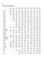
FIGURE
15
Phase-matching
cume
for
LiNbO,
for
a 1.061-ym pump.
through
22).
ZnGeP, could tune over this range with a variation of about
4",
the
smallest angular range; CdSe would require about 14", the largest angular range.
AgGaS, does display an unusually flat tuning range about
4.2
ym. Besides this.
the tuning curves are in general similar, except for the direction
of
the curvature.
As
such, selection of the best nonlinear crystal would probably be based on con-
siderations other than the phase matching curves.
9.
PERFORMANCE
Optical parametric oscillators have developed from their initial stage where
they were little more than
a
curiosity. Initial performance was limited by lack of
high optical quality nonlinear crystals. nonlinear crystals with relatively small
nonlinear coefficients. and limited pump laser performance. In addition, optical
parametric oscillators were in competition with dye lasers in the visible and near
infrared. Pulsed dye lasers have an advantage because laser-pumped dye lasers do
not necessarily require high beam quality from the pump laser. In essence, dye
lasers can serve as an optical integrator, converting a fixed-wavelength pump laser
with relatively poor beam quality into a tunable laser with a better beam quality.
In the face of these difficulties, optical parametric oscillators enjoyed limited com-
mercial applications for a considerable time. However, several increases in optical
parametric oscillator technology have improved the viability of these devices.
7
Optical Parametric Oscillators
335
1.064~rn
Pump
\
20 22 24 26 2%
Angle (degrees)
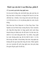
FIGURE
16
Phase-matching curve
for BBO
for
0.537-
and
1.064-pm
pumps.
Opticall quality of the nonlinear crystals has improved. Optical quality
improvements have occurred both in the form of decrcased absorption and
decreased distortion. For example, LiNbO, crystals were found
to
suffer from
optically induced refractive index inhomogeneities.
It
was found that, in part,
these probllems could be traced to Fe impurities. By decreasing the Fe impuri-
ties, the susceptibility of optically induced refractive index inhomogeneities was
decreased. Similarly. the short-wavelength absorption in AgGaSe, was corre-
lated with
a
deficiency of Se. By annealing these crystals in an atmosphere rich
in
Se, the short-wavelength transmission of these crystals improved. Initially
some nonlinear crystals were deliberately doped with impurities to reduce
growth time and therefore cost. While some impurities are benign, others can
cause unwanted absorption. Increased absorption can limit the efficiency and
average power limit mailable with a given nonlinear crystal. In addition, some
crystals tended to grow multidomain. That is, not all of the nonlinear crystal was
oriented
in
the same manner. Multidomain crystals limit efficiency by limiting
the effective length of the nonlinear crystal.
As
growth technology improved,
many of these problems were resolved.
336
Norman
P.
Barnes
12.0
11.0
1,
1.064pm
Pump
t
\
FIGURE
35
39
43
47
51
Angle (degrees)
1
7
Phase-matching
curve
for
AgGaS,
for
a 1.061-pn
pump.
Of perhaps more significance is the introduction of better nonlinear crystals.
particularly ones with a larger nonlinear coefficient. Of particular note in the
way
of
visible crystals are
KTP,
BBO,
and
LBO.
Crystals with nonlinear coeffi-
cients as large as those available with these more recent crystals were not gener-
ally available in the early developmental stages of optical parametric oscillators.
In the infrared, AgGaSe, has developed to the point where it is presently com-
mercially available for applications in the mid-infrared region. Although this
crystal has been known for some time, the availability and the absorption in the
near-infrared region limited its utility. In addition. substantial progress has also
been made with the commercialization
of
ZnGeP,.
Pump lasers have also improved both in power and beam quality, a definite
advantage when nonlinear optics are being used. Improvements such as unstable
resonators and graded reflectivity output mirrors have made pump lasers with good
beam quality as well
as
high energy per pulse available.
The
beam quality of pump
lasers is often limited by thermal effects. However, as laser diode array pumping
of
solid-state lasers becomes more common, the beam quality should improve even
more since the thermal load on a laser diode array-pumped solid-state laser
is
less
than a similar lamp-pumped solid-state laser at the same average output power. In
addition, injection seeding techniques have narrowed the linewidth of the pump
7
Optical Parametric
OsciIIators
337
12.0
11.0
10.0
h
$
9.0
E
7.0
+
a,
E
8.0
e
v
5
6.0
0,
C
2
5.0
a,
>
3
4.0
3.0
2.0
1
.o
I
I
I
I
30
32
34
36
38
Angle (degrees)
FIGURE
1
8 Phase-matching
cune
for
AgGaS,
for
a
2.10-pn
pump
lasers. Both increased beam quality and decreased linewidth can lead
to
an
increased performance for the optical parametric oscillator.
Several different concepts are involved in the assessment of the performance
of an optical parametric oscillator including threshold, slope efficiency, total
effi-
ciency. photon efficiency, and pump depletion. Optical parametric oscillators can
be operated either in a cw or a pulsed mode. Of the two modes of operation. the
pulsed mode is much more common since the operation
of
an optical parametric
oscillator is enhanced by a high power density. The threshold in the cwr mode
is
straightforward to define as the amount of pump power required to achieve opti-
cal parametric oscillation. In the pulsed mode. the observable threshold, rather
than the instantaneous threshold.
is
usually quoted; however. this is
not
alw ays
made clear. While slope efficiency
is
sometimes quoted, it could represent either
the ratio
of
the increase in power at the output wavelength to the increase
in
power at the pump wavelength or the increase
in
power of both the signal and
idler wavelengths to the increase in power at the pump wavelength. In the pulsed
mode. it could be quoted at the instant of peak power or it could
be
quoted for the
total output energy. Although laser theory usually predicts a nearly linear increase
in the output with increases
in
the input. optical parametric oscillator theory does
not necessarily predict the same approximation. However, in practice. a linear
338
Norman
P.
Barnes
12.0
11.0
10.0
9.0
8.0
0
5
7.0
6.0
ET,
5
5.0
a,
h
a,
c.
E
5
v
-
B
4.0
3.0
2.0
1.0
-
-
-
-
-
-
-
-
-
-
-
-
40
42
44 46 48
Angle (degrees)
FIGURE
1
9
Phase-matching
curve
for AgGaSe, for a 2.10-km pump.
increase of the output with the input is often observed. Total efficiency suffers
from many of the same ambiguities as slope efficiency. It could imply the output
power or energy at one or both
of
the signal and idler wavelengths divided by
the pump power or energy. Photon efficiency normalizes the pump power and
energy and the output power or energy by the energy of the pump and output
photon, respectively. Thus. a unity photon efficiency would imply that the power
or energy efficiency would be in the ratio of the pump wavelength to the output
wavelength. Pump depletion usually compares the pump pulse transmitted
through the optical parametric oscillator with and without oscillation occurring.
As
such, it
is
closest to the efficiency calculated using both the signal and idler
as outputs.
Optical parametric oscillation was first demonstrated using a pulsed pump
laser, a frequency-doubled Nd:CaWO, laser
[50].
The threshold was reported to
be sharp and well defined at
6.7
kW, but was only achieved
on
about one in five
shots. A peak output power of
15
W
at
a
signal wavelength of
0.984
pm
was
reported, yielding an efficiency
of
about
0.002.
Continuous wave optical parametric oscillation was reported by using a
Ba,NaNbjO,, crystal
[51].
It
was pumped by a frequency-doubled Nd:YAG
laser. A threshold of
45
mW was observed when the wavelengths available
7
Optical Parametric OsciI/atois
33
2.0
l.E
-
-
56
60 64 68
72
Angle (degrees)
FIGURE
20
Phase-matching
curve
for
CdSe
for
a
2.10-ym
pump.
ranged from 0.98 to
1.16
pm. With
0.3
W of pump power, the available power at
both the signal and idler wavelengths was estimated at 0.003 W, yielding
an
effi-
ciency of
0.01.
Later. by using a cw Ar ion laser for a pump laser,
a
threshold as
low as 2.0 mW was achieved. A power output of about
0.0015
W
was achieved
at about 2.8 times threshold. While a continuous pump was employed, the output
consisted
of
a series
of
pulses with pulse lengths ranging from
0.1
to
1.0
ins
in
length
[52].
More efficient operation in the near infrared was obtained by
two
researchers both using LiNbO, as the nonlinear crystal.
In
one case. a frequency-
doubled Nd:glass laser was used as the pump source [53], and the other used a
Q-switched Cr:A1,03 laser
[54].
In the first case; a threshold
of
z.bout
5.0
kW
was required for
-a
8.Q-mm crystal length. At twice threshold, a peak
output
power
of
1.8
kW
was
achieved yielding an efficiency of
0.18.
In the second case
a threshold of
65
kW
was achieved in a doubly resonant arrangement with
a
9.35-mm crystal length. With the doubly resonant arrangement, 0.22
of
the peak
pump
poweir
was converted to the signal at
1.04
pm.
On
the other hand,
with
a
singly resonant arrangement. only
0.06
of the peak pump power was converted
to
the signal. Although the efficiencies reported in these experiments are impres-
sive,
the
output energy of these devices is in the millijoule range or less.
340
Norman
P.
Barnes
h
2
9.0
W
c
8.0
o
7.0
6.0
m
5.0
Q,
2
4.0
3.0
L
5
E
5
v
-
3
12.0
10.0
I1.Ol
f
-
-
-
-
-
-
-
2.0
1
.o
t
I
50
52
54
56
58
Angle
(degrees)
FIGURE
2
1
Phase-matching
curve for ZnGeP,
for
a 2.10-pm
pump.
A device tunable across the visible region of the spectrum was produced by
using ADP as the nonlinear crystal
[SI.
A frequency-quadrupled Nd:YAG laser,
yielding about
1.0
mJ/pulse at
0.266
pm, was utilized as the pump. Gains were
high enough with this configuration that external mirrors were not necessary to
obtain significant conversion. With the 50-mm ADP crystal oriented normal to
the pump beam,
an
average power conversion of the pump to the outputs in the
visible region of the spectrum was as high as
0.25.
Temperature tuning the crys-
tal from
50
to
105°C
allowed the region from
0.42
to
0.73
pm to be covered.
A cw optical parametric oscillator tunable in the red region
of
the spectrum,
from 0.680 to
0.705
pm, was demonstrated using an
Ar
ion laser operating at
0.5145
pm in conjunction with a 16.5-mm LiNbO, crystal
[52].
To
avoid opti-
cally induced refractive index inhomogeneities, the crystal was operated at ele-
vated temperatures, nominally
240°C.
A threshold
of
410
mW was possible. At
2.8
times threshold,
1.5
mW of output power was available even though the out-
put mirror only had a transmission of approximately
0.0004.
An optical parametric oscillator tunable in the mid-infrared region was
obtained by using a Nd:YAG laser directly as the pump and a LiNbO, crystal
[56]. Operation in this region of the spectrum is more difficult because the gain
7
Optical Parametric Oscillators
341
12.0
11.0:
10.0
h
2
9.0
a
c
0.0
0
b
7.0
E
5
v
6.0
0)
$
5.0
a
-
z
4a
3.0
2.0
\
-
-
-
-
-
-
-
-
-
-
22 24 26 20
30
Angle (degrees)
FIGURE
22
Phase-matching
curve
for T1:.4sSe;
for
a
2.10-ym
pump.
coefficient is inversely proportional to the product
of
the signal and idler wave-
lengths.
To
help compensate for the low gain, a
50-mm-long
crystal was used.
Using angle tuning. the spectral range from
1.1
to
4.5
pm
could be covered. The
threshold was
4.0
mJ when the oscillator was operating near 1.7
ym.
An
energy
conversion efficiency of
0.15
was reported.
Optical parametric oscillation further into the mid-infrared region was POS-
sible by using a CdSe crystal. Initially, a Nd:YAG laser operating at 1.83
pm
was
used as the pump [57]. Later, a
HF
laser, operating around 2.87
ym
was used for a
pump
[%I.
In the former case, threshold for a 21-mm crystal length was observed
to
be between
0.55
and 0.77
liW.
A
power conversion efficiency of
0.40
was
inferred by measuring the depletion
of
the transmitted pump.
In
the latter case,
threshold for a
28-mm
crystal length was found to be
2.25
kW. At
about twice
threshold, a signal power of
0.8
kW
was observed that indicated a power efficiency
of
0.15.
By
employing angle tuning, a signal was generated over the range from
4.3
to
J.5
pm.
Corresponding to this. the idler was tuned between S.l
10
8.3
pm.
Optical jparametric oscillator operation can be enhanced
by
utilizing a mode-
locked pump
[59].
For
one set of experiments, a mode-locked Nd:glass laser.
operating
at-
1.058
ym.
was amplified to produce an output
of
0.55
J.
By
using an
342
Norman
P.
Barnes
etalon in the Nd:glass laser resonator, the pulse length could change from
7
to
60
ps. Using
a
KDP
crystal, this produced about 0.15
J
of second harmonic.
A
LiNbO, crystal with a length of
20
mm
was
utilized as the nonlinear crystal.
It
was housed in an oven
to
allow temperature tuning. With the optical parametric
oscillator tuned to 0.72 ym. an output of
6
mJ was achieved.
To
utilize the peak
power associated with the pump. the length of the optical parametric oscillator
had
to
be adjusted
so
that the circulating pulse was in synchronism with the inci-
dent pump pulse train. With
a
7.0-ps pulse length.
a
change in the length of the
resonator in the range of
0.1
mm produced
a
factor of
10
change in the output
energy. In a different experiment.
a
mode-locked Ho:YAG laser was used
to
pump a CdSe optical parametric oscillator
[60].
A
similar enhancement in the
conversion was effected by using the mode-locked pump pulse train.
An attractive optical parametric oscillator for use in the mid-infrared region
was demonstrated using AgGaSe, as the crystal. Although CdSe could cover
much of the mid infrared. its limited birefringence limited its tuning capability.
However, much of the mid infrared could be covered using long-wavelength
pump lasers including a 2.04-pm
Ho:YLF
[61]
or
a
1.73-pm Er:YLF [I71 laser.
Use of a 23-mm crystal length with the 1.73-ym pump resulted in a threshold of
3.6
mJ.
A
slope efficiency. measuring only the signal at 3.8 pm, of 0.31 at 1.5
times threshold was achieved simultaneously.
On
the other hand, with the 2.05-
pm
pump,
a
threshold of
4.0
mJ was achieved along with an energy conversion
into both the signal and idler of 0.18.
Substantial energy conversion has been demonstrated using BBO as the
nonlinear conversion by
two
different groups. Both groups used the third har-
monic of a Nd:YAG as the pump.
In
one case.
two
opposed crystals, one 11.5
mm in length with the other
9.5
mm in length, were used
to
minimize birefrin-
gence angle effects
[62].
Efficiency in this case is defined as the sum of the sig-
nal and idler energy output divided by the incident pump energy. Here signifi-
cant saturation in the conversion efficiency
was
observed, nearly 0.32; that
is,
7
mJ
of
output energy for
21
mJ of pump. In the other case,
a
10-mm crystal
length yielded a quantum conversion efficiency as high as 0.57 at a signal
wavelength of 0.49
pm
by double passing the pump through the nonlinear
crystal
[63].
By simply using more energetic pump lasers. more output energy can be
obtained. By using a Nd:YAG oscillator and amplifier, a pump energy
of
about
0.35 J/pulse could be obtained. Using two opposed KTP crystals 10 mm in
length. for birefringence angle compensation. a nearly degenerate optical para-
metric oscillator was demonstrated
[63].
Signal and idler wavelengths were
I
.98
and
2.31
ym, respectively. The threshold for this arrangement was about 100 mJ
and the slope efficiency was as high as
0.48.
At the full input energy. 0.115
J/pulse
was
produced. Even higher energy per pulse could be obtained by simply
scaling the device in cross section while retaining the same energy density.
7
Optical Parametric Oscillators
343
10.
TUNING
Tuning of the opical parametric oscillator can be handled using the same
techniques as described in the chapter on solid-state lasers (Chapter
6;
see also
Chapter
2).
However, significant differences do exist that can be attributed to the
difference in the operating principles of the two devices. Some of these differ-
ences are manifest in the coarse tuning available with phase matching
of
the
optical parametric oscillator and in the time-varying instanteous gain,
A
hich has
to be taken into account if injection seeding is to be utilized. However, because
many of the tuning and line narrowing elements are discussed in Chapter
6,
the5
will not be discussed here. Rather, the tuning aspects unique to the optical para-
metric oscillator will be emphasized.
Coarse tuning of Lhe optical parametric oscillator can be accomplished using
either angular or temperature tuning. In fact. any effect that causes a differential
change
in
the refractive indices at the pump. signal. and idler wavelengths could
be used to effect tuning. For example, tuning could be achieved using an applied
pressure through the stress optic effect. However, to date, only angular or tem-
perature tuning has received wide application.
To
calculate the tuning rate, the
partial derivatives of the phase mismatch can be used. According to a theorem
in
partial differential calculus.
Using this relation, the tuning rate can be approximated by
for angular tuning and
for temperature tuning.
To
evaluate the derivatives of
Ak
with respect to the direc-
tion
of
propagation and temperature. the results of Sec.
1
can be used. Thus.
in general. Of course, the partial derivative lvith respect to angle for ordinary
waves
is
zero in uniaxial crystals. For temperature tuning.
344
Norman
P.
Barnes
Individual partial derivatives with respect to angle are evaluated in Section
4.
Partial derivatives of the index of refraction with respect to temperature are
listed for the more common crystal in Section
8.
Thus, to determine the particu-
lar wavelength that will be generated. the phase-matching condition can be cal-
culated as done for a variety of situations in Section
8.
Tuning near the phase-
matching condition can then be found by using the preceding equations.
Linewidth can be determined by using the approach also described in Section
4.
Injection seeding of
an
optical parametric oscillator can be accomplished in
much the same way as injection seeding
of
a solid-state laser. Injection seeding
has been demonstrated for several optical parametric oscillators operating in the
visible and mid-infrared regions
[65-671.
However, there are several significant
differences between seeding an optical parametric oscillator and injection seed-
ing a solid-state laser
[67].
One of these differences occurs during the critical
pulse evolution time interval. During this phase of the development, not much
energy is extracted. However, the spectral properties
of
the output are deter-
mined by the competition between the seeded and unseeded modes. In a solid-
state laser, the gain is nearly constant since the stored energy or the population
inversion density is nearly constant. In an optical parametric oscillator, the gain
varies with the pump power. Thus, for a pulsed pump, the gain varies with time.
Although this makes the description of the competition more complex, it does
not prevent seeding.
A
second difference is in the extraction of the energy.
In
a
solid-state laser, as the seeded mode extracts the energy stored in the upper laser
level, it hinders the development of the unseeded mode by decreasing its gain.
However, in an optical parametric oscillator, there is no stored energy. Thus for
injection seeding to be highly successful. the seeded pulse should continue to
extract the energy from the pump pulse as fast as it arrives at the crystal.
A
third
difference exists in the saturation effect. In a solid-state laser the laser pulse
extracts the energy stored in the upper laser level to the point where the gain
falls to zero. However, in an optical parametric oscillator, the gain may not fall
to zero in the presence on the seeded pulse. A nonzero gain allows the unseeded
modes to continue to extract energy from the pump and thus decrease the effi-
cacy of the seeding process.
In doubly resonant optical parametric oscillators, spectral output of the device
may be unstable due to
an
effect referred to as the cluster effect. If both the signal
and idler are resonant, oscillation can
only
occur at frequencies that satisfy both
the conservation of energy and the resonance condition. Because
of
these simulta-
neous requirements, the frequencies that oscillate may not occur at the minimum
phase mismatch as shown in Fig.
23.
By operating away from the point at mini-
mum phase mismatch, the output can be significantly reduced. Worse still, the
7
Opticat
Parametric
Oscillators
345
f
ilvv+O
Ak=o
I
1
I
I
I
I
1
I
I
I
I
I
I
-Increasing Signal Frequency-
;
-increasing Idler Frequency-
FIGURE
23
Cluster effects in doublJ resonant devices.
closest set
of
frequencies that satisfies both the resonance condition and the con-
servation
of
energy can vary
on
a shot-to-shot basis.
For
example, the pump fre-
quency may experience small variations caused by small variations
in
the level
of
excitation
oE
the pump laser.
A
small variation
in
the pump frequency may cause a
much larger difference in the frequencies that satisfy both the conservation of
energy and the resonance condition. Due to instabilities associated with the cluster
effect, the doubly resonant optical parametric oscillator is often avoided.
REFERENCES
1.
J.
A.
Giordmaine and
R.
C. Miller. “Tunable Coherent Parametric Oscillation in LiNbO; at Opti-
2.
J.
A.
Amsrrong,
N.
Bloernbergen.
J.
Ducuing, and P.
S.
Pershan. ”Interactions between Light
3.
G.
D. Boyd and D.
A.
Kleinnian, ”Parametric Interaction
of
Focused Gaussian Light Beams,”
J.
4.
S.
E.
Harris. ”Tunable Optical Parametric Oscillators,”
Proc.
IEEE
57,2096-21 13 (1969).
5.
S.
J.
Brosaan and
R.
L.
Byer. “Optical Parametric Oscillator Threshold and Linewidth Studies.”
6.
R.
L.
Byer and
S.
E.
Harris, ”Observation
of
Tunable Optical Parametric Fluorescence.”
Phxs.
7.
N.
P. Barnes and
V.
J.
Corcoran, ’:i\cceptance Angles and Spectral Bandw.idths
of
Nonlinear
8.
N.
P.
Barnes. “Tunable Mid Infrared Sources Using Second Order Nonlinearities,”
Int.
J.
Nonlin-
9.
P. N. Butcher, Nonlinear
Optical Phenomer~a,
Bulletin
200
Ohio State University, Columbus,
cal Frequencies,”
Phyx. Rei: Lerr.
11,
973-976 (1965j.
Waves in a Nonlinear Dielectric.”
Php.
Rei:
127, 1918-1938 1.1962;).
Appl. Phys.
39,3597-3639 (1968).
IEEE
J.
Quantum
Elect?-on.
QE-15,115431
(1979).
Rev.
Lerr.
18,732-731
(1968j.
Interactions,”
Appl. Opt.
15, 696-699 (1976).
em-
Opr.
1,639-672 (1992).
OH
(1965).
10.
Nl.
Born and
E.
Wolf.
Principles QfOprics,
Pergamon Press. New York
(1961).
11.
E
Zemike and
J.
E.
Midwinter,
ilppliediVonlb7eczr Oprirs.
U‘iley,
Ne\%
York
(
1973).
346
Norman
P.
Barnes
12.
J.
A. Xrmstrong, N. Bloembergen,
J.
Ducuing. and P.
S.
Pershan, “Interactions Between Light
13.
G. D. Boyd and D.
A.
Kleinman. “Parametric Interactions of Focused Gaussian Light Beams.”
J.
14.
R.
A.
Baumgartner and
R.
L.
Byer, ‘.Optical Parametric Amplification,“
IEEE
J.
Quantum
Elec-
15.
N. P. Bames. D.
J.
Gettemy,
J.
R. Hietanen, and R.
A.
Iannini, “Parametric Amplification in
AgGaSe,,”Appl. Opr.
28,5162-5168 (1989).
16.
S.
J.
Brosnan and R.
L.
Byer, ”Optical Parametric Oscillator Threshold and Linewidth Studies;’
IEEE
J.
Quantum
Electron.
QE-15,115431 (1979).
17.
N. Barnes:
K.
E.
Murray.
J.
R. Hietanen, and R.
4.
Iannini. ”Er:YLF Pumped AgGaSe, Optical
Parametric Oscillator,” in
Proc.
OSA
Adwmced Solid
Srare
Lasers.
OSX.
Washington. D.C.
322-328 (1990).
18.
S.
J.
Brosnan and R. L. Byer, ”Optical Parametric Oscillator Threshold and Linwidth Studies.”
IEEEJ.
Quamiin
Electron.
QE-15,415431 (1976).
19.
N. P. Barnes,
J.
A.
Williams,
J.
C. Barnes, and G.
E.
Lockard.
“A
Self Injection Locked
Q-
Switched Line Nmomed Ti:A120, Laser,”
ZEEE
J.
Qiiaizrunz Electron.
24,
1021-1028 (1988).
20.
G.
D. Boyd. A. Ashkin,
J.
M.
Dziedzic, and
D.
A.
Kleinman, ‘Second Harmonic Generation of
Light with Double Refraction,”
Phys.
Rei:
137, A1305-Al319 (1965j.
21.
S.
J.
Brosnan and R.
L.
Byer. ‘.Optical Parametric Oscillator Threshold and Linewidth Studies,”
ZEEEJ.
Qziuntum
Elecrron.
QE-15, 415431 (1979).
22.
M.
Okada and
S.
Ieiri, “Influences
of
Self-Induced Thermal Effects on Phase Matching in Non-
linear Optical Crystals,”
ZEEE
J.
Qiiaiztum
Elecrron.
QE-7,560-563 (1971).
23.
N.
P. Barnes, R.
C.
Eckhardt, D.
J.
Gettemy, and
L.
B.
Edgett, ”Heating Effects in Second Har-
monic Generation.” in
LIS
Info?-mation
Eschange
Meering,
Albuquerque.
Nh4
(May
1977).
24.
D. T. Hon and
H.
Brusselbach. “Beam Shaping to Suppress Phase Mismatch in High Power Sec-
ond Harmonic Generation,”
ZEEE
J.
Qtianrzim
Electron.
QE-16, 1356-1361 (1980).
25.
D. Eimerl, “The Potential for Efficient Frequency Conversion at High Average Power Using
Solid State Nonlinear Optical Materials.’’ UCID-20565, University of California (Oct.
1985).
26.
T.
G.
Giallorenzi and
C.
L.
Tang, TW Parametric Scattering in ADP with Strong Absorption in
the Idler Band ’Appf.
Phys.
Lett.
12,37&378 (19683.
27.
J.
D. McMullen, “Optical Parametric Interactions in Isotropic Materials Using a Phase Corrected
Stack of Nonlinear Dielectric Plates.”J. .Appl.
Phxs.
46, 3076-3081 (.1975).
28.
E
Zemike and
J.
E.
Midwinter, Applied
Nonlinear
Optics, Wiley. New York
(1973).
29.
V.
G.
Dmitriev. G.
G.
Gurzadyan, and D. N. Nikogosyan, Handbook
ofNonliizear
Oprical
Cr~s-
ruls.
Springer Verlag. New York
(1991
j.
30.
M.
J.
Weber.
Handbook
of
Laser
Science
and
Technology.
1’01.
IZZ.
Optical
,Vfarerials,
CRC
Press, Boca Raton,
FL
(1986).
31.
M.
M.
Choy and R. L. Byer. ”‘Accurate Second Order Susceptibility Measurements
of
Visible
and Infrared Nonlinear Crystals,”
Phys.
Rev.
B.
14,
1693-1706 (1976).
32.
R.
C. Eckhardt, H. Masuda, Y.
X.
Fan, and R.
L.
Byer, ”.Absolute and Relative Nonlinear Optical
Coefficients of KDP.
KD*P,
BaB,O,, LiIO,, MgO:LiNbO,. and KTP Measured by Phase-
Matched Second-Harmonic Generation,”
ZEEE
J.
Quantum
Electron.
QE-26,922-933 (1990).
33.
I. H. Malitson, and M.
J.
Dodge, ”Refractive Index and Birefringence of Synthetic Sapphire.”
J.
Opr. Soc.
Am.
62, 1405 (1972).
34.
E
Zernike, “Refractive Indices
of
Ammonium Dihydrogen Phosphate and Potassium Dihydro-
gen Phosphate Between 20004 and
1.5
pm,”J. Opr.
Soc.
Am.
51,1215-1220 (1964).
35.
L.
G.
DeShazer and K. E. Wilson, “Refractive Index and Thermo-Optic Coefficients
of
CD*A,”
in
Basic
Properties
of
Optical
Marerials
Symp., NBS Special Publication
571,
Gaithersburg. MD
(1980).
36.
G.
D. Boyd. W. L. Bond, and H. L. Carter, ’-Refractive Index as a Function of Temperature in
LiNb0,“J. Appl.
Phys.
38,1941 (1967).
Waves in a Nonlinear Dielectric,”
Phys.
Rev.
127, 1918-1938 (1962).
Appl.
Phys.
39,3597-3639 (1968).
rro>z.
QE-15,332111(1979).
7
Optical Parametric Oscillators
347
37.
D. Eimerl. L. Davis, and
S.
Velsko,
E.
K.
Graham. and
A.
Zalkin, ”Optical. Mechanical. and
Thermal Properties of Barium Borate.”J.
.4ppl.
Phys.
62, 1968-1983 (1987).
38.
C. Chen,
Y.
Wu,
A.
Jiang. B.
\Vu.
G.
You
e[
nl.,
”New Nonlinear Optical Crystal: LiB,0j5.”
L
Opr.
SOC.
Am.
B
6,616621 (1989j.
39.
T. Y. Fan, C. E. Huang. R.
C.
Eckardt.
Y.
X.
Fan, R. L. Byer, and R.
S.
Feigelson. “Second Hx-
monic Generation and Accurate Indices of Refraction Measurements in Giux-Crown KTiOPO,,”
Appl.
Opt.
26,2390-2391
i
1987).
40.
G. D. Boyd.
H.
Kasper, and
J.
H. McFee. “Linear and Nonlinear Properties
of
AgGaS,. CuGaS,
and CuInS,. and Theory of the Wedge Technique for the Measurements of Nonlinear Cos%-
cients,”
IEEE
J.
Qimmmz
Elecn-017. QE-7,
563-573 (1971
).
11.
G. D. Boyd. H.
hl.
Kasper.
J.
H. McFee, and
F.
G.
Storz. “Linear and Nonlinear Optical Proper-
ties of Some Ternary Selenides,”
I€€E
J.
Quaiifmi
Elecfron.
QE-8,
900-908 (1972).
47.
R. L. Herbst and R.
L.
Byer, ’-Efficient Parametric hlixing In CdSe,”
.4pp!.
Pkjs.
Left.
19,
527-530 (1971).
13.
G. D. Boyd, E. Buehler, and
E
G. Storz. -’Linear and Nonlinear Properties
of
ZnGeP,
and
CdSe.”A4ppl.
Phys.
Lerr.
18,
301-304 (1971).
11.
J.
D.
Feichtner and G.
W.
Roland, ”Optical Properties
of
a New Nonlinear Optical Material:
Ti,AsSe,.”ilppl.
Opr.
11,
993-998
i
1972).
15.
N.
P. Barnes, D. J. Gettemy. and
R.
S.
Adhav. “Variation
of
the Refracthe Indices 1Tith Tempera-
ture and the Tuning Rate for KDP Isomorphs,”J.
Opr.
SOC.
.4m.
72,895-898
(
1982).
16.
L.
G.
DeShazer, C.
S.
Hoefer. and K.
IV.
Kirby. “Optical Characterization
of
Nonlinear Cps-
tals.” Final Report
to
Lawrence Livermore National Laborator!. Livermore, CA
(1
985’1.
47.
D.
J.
Gettemy.
\V.
C. Harker. G. Lindholm. and N. P. Barnes. “Some Optical Propertiss of KTP,
LiIO,,
and LiNbO,,”
lEEE
J.
Qunnrzon
Elecrron.
QE-21,
223 1-2237
i
1988).
18.
R.
L Herbst. ”Cadmium Selenide Infrared Parametric Oscillator,” Microwave Laboratory Report
2 125.
Stanford University. Stanford. CA
11972).
49.
M.
D. Ewbank. P. R. Newman.
N.
L. hlota.
S.
hf.
Lee,
IV.
L. Wolfs
er
al
’.The Temperature
Dependence of Optical and hlechanical Properties of TI,AsSe,.”
J.
.4ppl.
Phjs.
51,
38-18-3851
(1980).
50.
J.
A.
Giordmaine and
R.
C.
hliller. “Tunable Coherent Parametric Oscillation in LiNbO, ar Opti-
cal Frequencies.”
Phjs.
Rey.
Letr.
11,
973-976 (1968).
5
1.
R.
6.
Smith,
J.
E. Gzusic,
H.
J.
Levinstsin.
J. J.
Rubin.
S.
Singh. and L. G. Van Uitert, “Continu-
ous
Optical Parametric Oscillation in BalNaNbjO,
j.”
Appl.
Pliys.
Lerr.
12.
308-309 (1968).
52.
R.
L. Byer.
M.
K.
Oshman.
J.
E
Young. and
S.
E.
Harris, “Visible CU‘ Parametric Oscillator.”
.&id.
Phys.
Len.
12,
109-1
11
(1968).
53.
L.
B. Kreuzer. ”High Efficiency Optical Parametric Oscillator And Power Limlting
In
LiNbO,,“
,4ppl.
Phys.
Lerr.
13,
57-59 (1968).
51.
J.
E. Bjorkholm, “Efficient Optical Parametric Oscillation Using Doubl! Resonant and Singly
Resonant Cavities.”.4ppl.
Phys.
Len.
13.53-56
(
1968).
55.
J.
hl.
Yarborough and G.
A.
hfasseq. ”Efficient High Gain Paramerric Generation in
.XDP
Con-
tinuously Tunable across the Visible Spectrum.”
lppl. Plrys.
Lerr.
18,438440
(197
1
).
56.
R.
H.
Herbst,
R.
N. Fleming, and R.
L.
Byer,
“A
1.44.0
pm
High Energy .Angle Tuned LiNbO,
Optical Oscillator ’
Appl.
Phys.
Lerr.
25.520-522 (1974).
57.
R.
L.
Herbst and R. L. Byer. “Singly Resonant CdSe Infrared Parametric Oscillator.”;Ippl.
Phys.
Lerr.
21,
189-191 (1972).
58.
J.
A.
Weiss and
i.
S.
Goldberg, “Singly Resonant CdSe Parametric Oscillator Pumped by an HF
Laser.”;?ppl.
Phjs.
Left.
21,
389-391 (1971).
59.
T. Kushida,
Ti
Tanaka, and
M.
Ojima. ”Tunable Picosecond Pulse Generation b! Optical Para-
metric Oscillator,”
Jup.
1.
App.
Plz~s.
16, 2227-2235 (19773.
60.
G.
E’.
Arnold,
N.
P. Barnes. and
D.
J.
Gettemy. and
R.
G.
Wenzel. ’ L\nomalous Behavior
or
Some
Synchronously Pumped Mode Locked Parametric Oscillators,“ in
Lasers
80,
Nen
Orleans,
LA
(Dec.
1980).
348
Norman
P.
Barnes
61.
R.
C.
Eckhardt, Y.
X.
Fan, R.
L.
Byer. C. L. Marquardt.
M.
E. Storm, and
L.
Esterowitz.
‘-Broadly Tunable Infrared Parametric Oscillator Using AgGaSe:?”
Appl.
Phy.
Lerr.
49,608-610
(1986).
62.
W.
R.
Bosenberg.
W.
S.
Pelouch, and C.
L.
Tang, “High Efficiency and Narrow Linewidth Oper-
ation of a Two Crystal kBaB,O, Optical Parametric Oscillator.”
Appl.
Phgs.
Len.
58,
1461-1463 (1991).
63.
Y.
Wang, Z. Xu, D. Deng,
W.
Zheng, X. Liu
et
al
“Highly Efficient Visible and Infrared
@BaB,O, Optical Parametric Oscillator With Pump Reflection,”
Appl.
Phys.
Letr.
58,
1461-1463 (1991).
63.
S.
Chandra,
M.
J.
Ferry. and G. Daunt,
’‘1
1.5
mJ, 2-Micron Pulses by OPO in KTP,” in Advanced
Solid
Srufe
Laser
Con$.
Santa Fe. NhT (Feb.
1992).
6.5.
V.
L. Boichenko,
M.
M. Novikov, and
A.
I.
Kholodnykh. “Improvement in the Output Character-
istics
of
a Pulsed Optical Parametric Oscillator
on
Injection of an External Signal into an Extra-
cavity Wave.”
Sov.
J.
Quanr.
Elecr.
17,392-393 (1987).
66.
W.
R.
Bosenberg, D.
R.
Guyer. and
C.
E. Hamilton, “Single Frequency Optical Parametric
Oscillators,.’ in
CLEO
Conf.,
Baltimore, MD (May,
1993).
67.
N.
P.
Barnes, G. H. Watson, and
K.
E.
Murray, “Injection Seeded Optical Parametric Oscillator,”
in
Adiianced
Solid
Stare
Laser
Conf.,
Santa Fe, Nhsl (Feb.
1992).
Tunable External-Cavity
Semiconductor
Lasers
Paul
Zorabedian
Photonics
Technology Depar-mient
Hevvlett-Puckar-d Labor-utories
Pulo
Alto,
Culqomiu
1,
INTRODUCTION
1
.l
What
Is
an External-Cavity Laser?
A
tunable external-cavity laser
(ECL)
(Fig.
1)
comprises an optical gain
medium
(a
laser diode with antireflection coatings on one or both facets), optics
for coupling the output of the gain-medium waveguide to the free-space mode
cf
the
externall cavity, one or more wavelength-selective filters, and one or more
mirrors
for defining an external feedback path. possibly with a piezoelectric
translator (PZT) for fine tuning. The external cavity may also contain additional
components such as polarization optics. bearnsplitters, prisms. telescopes. etc.
1.2
Why
Apply
External
Feedback
to Laser
Diodes?
7.2.
limitations
of
Diode
lasers
Semiconductor Fabry-Perot diode lasers
are
compact and easy
to
use,
but
they suffer from a number
of
performance limitations that are potentially serious
in many applications: Solitary laser diodes are often multimode, and they exhibit
large linewidths due to a short photon cavity lifetime and strong coupling
Ticnnhie
Larws
Handbod
Coplnphr
0
1995
b>
Academic
Press.
Inc.
All
rights
of
reproduction
in
an)
form
rsser\,ed.
349
350
Paul
Zorabedian
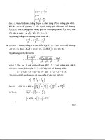
CAVITY
CONTROL
\
LENGTH
PZT
DIODE
FIGURE
1
Generic
tunable
extended-cavity
diode
laser.
between the phase and amplitude of the intracavity optical field. Laser diodes are
somewhat tunable by varying temperature or current. but these methods are awk-
ward and have limited ranges, which do not fully exploit the broad semiconduc-
tor gain bandwidth.
I
.2.2
Advantages
of
External-Cavity Lasers over Solitary Diode lasers
ECLs retain in large measure the compactness and ease
of
use of solitary
cavity diode lasers and in addition provide a number of performance enhance-
ments.
A
typical semiconductor ECL has a volume of
-1000
cm3.
A
properly
designed ECL will operate on a single external-cavity longitudinal mode. The
density
of
accessible modes is increased by the ratio
of
the external to solitary
cavity lengths. Truly phase-continuous tuning without mode hops is also pos-
sible. The linewidth of ECLs is greatly reduced in comparison to solitary diode
lasers because of the longer photon lifetime
of
an external cavity. The use
of
an
external filter allows tunability across the wide gain bandwidth
of
the semicon-
ductor gain medium.
7.2.3
Comparison
with
Other Types
of
Tunable lasers
Compared to other types of tunable lasers, external-cavity semiconductor
lasers are compact, are easily pumped by direct injection current excitation, have
high wallplug efficiency, are air cooled, and have long lifetimes. However, their
output power is generally lower (typically
-1
to
10
mW, although up to
1
W
has
been reported).
8
Tunable External-Cavity Semiconductor Lasers
3
1.3
Brief History
of
ECL
Development
Several papers on external cavity lasers appeared in the early 1970s. Some
of
these authors recognized a number
of
the basic issues of concern to the present-
day designer and user of ECLs. In the late 1970s several papers were also pub-
lished in the Soviet literature. The paper by Fleming and Mooradian in 1981
is
the earliest reference cited by many authors. since they were the first
to
stu@ the
spectral properties of ECLs in detail.
Considerable work was done in the early to mid-1980s at British Telecom
Research Laboratories, motivated by the prospect of using ECLs as transmitters
and local oscillators in coherent optical communication systems. In a similar
vein, the mid-
to
late 1980s saw a great deal
of
work at AT&T Bell Laboratories.
Eventually, the telecommunication companies realized that distributed feedback
lasers (DFBs) and distributed Bragg reflector lasers (DBRs) would better
suit
their needs. The end
of
the 1980s and early 1990s saw growing interest in
ECLs
as sources for spectroscopic work and in commercial fiber optic test equipment.
7.4
Scope
of
ECL
Discussion
This chapter considers lasers operating in the strong-external-feedback
regime. This generally requires devices with facets that have dielectric anti-
reflection (AR) coatings or tilted-stripe devices where the light exits the facet at
the Brewster angle.
This chapter deals mainly ufith the design and continuous wave (cw) proper-
ties
of laser diodes coupled
to
free-space external cavities using bulk optical
lenses, prisms, filters, and mirrors. Some treatment
of
integrated optic external
cavities
is
also
given. We exclude the treatment of the important rnonolithically
tunable DFB and DBR lasers. The rationale for this is that the design of these
lasers
is
very specialized and their fabrication requires sophisticated equipment
that necessarily limits the number
of
organizations that can produce them.
Broadband tuning of DFB lasers over ranges comparable to
ECLs
has been
obtained [l]. However the linewidths of these lasers are
2
to
3
orders
of
magni-
tude broader than that obtainable with ECLs.
We also do not explicitly consider vertical-cavity surface-emitting diode
lasers (VCSELs). By their structure these lasers are well suited to Isw-cost, high-
density
uses
in computer networks, but their short active regions provide
low
gain
and require very high cavity
Q
to achieve oscillation.
At
present, vertical-
cavity lasers are limited
to
those materials systems that can be grown on
GaAs
substrates. This has restricted the spectral coverage to wavelengths below
1
pm.
So
far. the goal of the few published external-feedback studies on VCSELs
is
from the point
of
view of their applications to optical signal processing
and
optical communications. They have comparable feedback sensitivity
[2]
and
behave in agreement with theory developed for edge-emitting laser diodes
[3].
352
Paul
Zorabedian
To the best of my knowledge.
no
work has been published
so
far with the intent
of achieving tunability because their low gain will not support much insertion
loss for external cavity components. However. if
VCSELs
continue to grow in
importance as some predict. greater adaptation to their use in external cavities
may follow.
2
SEMICONDUCTOR OPTICAL GAIN MEDIA
2.1
Laser Diode Basics
A semiconductor laser diode (Fig.
1)
serves as the gain medium of an
ECL.
The laser diode is a semiconductor device about
250
to
500
pm long by about
60
ym thick mounted on a copper or ceramic heat sink. Current is injected through
a top ohmic contact. Photons are generated and guided by the epitaxial layers of
the structure. The thin layer in which electrons and holes recombine to produce
light is called the
acth?e
region.
Stimulated emission in the active region forms
the basis for laser action driven by optical feedback from the facets or from the
external cavity. We start by reviewing some
of
the basic properties of laser
diodes, which are important for the design of
ECLs.
2.2
Light
Output versus Current Curve
The light output versus current
(L-Z)
curve (Fig.
2)
is characterized by the
threshold current
Z,,
and the quantum efficiency
q.
Saturation at high current is
caused by ohmic heating and Auger recombination. The linear portion of the
L-Z
curve is explained by the laser diode gain model.
2.3
Gain Model
2.3.
7
Gain
The optical gain
g
varies nearly linearly with injected carrier density
N:
where
o
is the differential gain cross section and
NT
is the carrier density
required for transparency.
2.3.2
loss
The active region contains optical losses such as free-cmier absorption,
scattering, and other possible effects. These factors make
up
the active-region
8
Tunable External-Cavity Semiconductor lasers
353
Ith
I
FIGURE
2 Schematic light output
versus
current
curve.
internal
loss
given by
al,,.
The cleaved-facet ends
of
the active region constitute
a mirror
loss
amil.
given by
where
Lint
is
the physical length of the internal cavity bounded by the facets with
power reflectances
Rfl
and
Rf2.
The Fresnel reflectance of a bare facet
is
where
17
=
3.5
is the semiconductor index of refraction.
2.3.3
Confinement Factor
gain. The factor
l-
is called the confinement factor.
2.3.4
Threshold Condition
Only a fraction
r
of the optical field lies within the active region and sees its
The threshold condition requires the optical field to be periodic with respect
to
one round-trip
of
the diode cavity. This leads to magnitude and phase condi-
tions
on
the optical field. The magnitude part of the threshold condition requires
the gain
g,,
to
be equal to the total round-trip
loss:
354
Paul
Zorabedian
2.3.5
Output
Power and Quantum Efficiency
Below threshold, the carrier density is proportional to the injection current.
Once the laser diode begins to oscillate. the carrier density is clamped at the
threshold value given by
The threshold current
It,,
is given
by
where
q
is the electronic charge. is the volume of the active region, and
tc
is
the carrier lifetime. Above threshold, the relation between output power
Po,,
and
injection current
Z
is given by
The differential quantum efficiency
q,,,
is given by
-
hv
a
mir
r\
exr
-
7
'l
int
a
mir
+
a
inr
where
q,,,
is the probability of radiative recombination for carriers injected into
the active region, which is close to unity for most semiconductor lasers
[4].
2.4
Spectral Properties
of
Output
2.4.7
Diode Laser Axial Modes
The phase part of the threshold condition specifies the axial modes of the
diode laser. The frequencies
V,
and wavelengths
hq
of the Fabry-Perot modes
of
the
solitary diode laser are given by
where
q
is
an
integer.
c
is the velocity of light,
ne%
is the index of refraction, and
Lint
is the physical length of the active region. The frequency spacing between
diode laser axial modes is thus given by
8
Tunable External-Cavity Semiconductor Lasers
355
Assuming
neff
=
3.5
and
Lint
=
250-500
pm, we find
Avint
=
85
to
170
GHz.
Many Fabry-Perot diode lasers, especially long-wavelength InGaAsP lasers,
will
oscillate in several axial modes simultaneously in the absence
of
a wave-
length-selective element in the cavity.
2.4.2
Linewidth
Schawlow-Townes foimula
[5]:
The linewidth of a solitary single-mode laser diode is given by the modified
where
u,
is the group velocity,
n
for AlGaAs and InGaAsP lasers
is
about
2.6
and 1.6.;espectively, and
a
is the linewidth broadening factor.
2.4.3
Linewidth Broadening factor
SP
The semiconductor index of refraction consists
of
real and imaginary parts
ti
=
11'
+
in"
.
(12)
The real and imaginary parts are strongly coupled compared to other laser gain
media. The strength of this coupling is characterized by the
line*i*idth hr-ocrdeiz-
itig
fictor
a,
defined as
An'
An"
.
a=-
(13)
The
a
parameter is the ratio of the changes in the real and imaginary parts of the
refractive index with a change in the carrier density. The linewidth broadening
factor
is
a
positive number with typical values in the range
of
4
to
7
near the
middle of the optical gain band and rising steeply to values of
10
to
20
as the
photon energy approaches the band gap [6]. At each wavelength, the value of
Q
increases with higher injection current
[7].
The degree of dependence
of
the
C!
parameter
on
device geometry depends
on
the type of active region
[SI.
For
index-guided lasers (see discussion later), the
a
parameter is
not
strongly depen-
dent
on
device geometry; that is, it is close to the value for bulk material. For
gain-guided and quantum-well laser diodes
a
may be geometry dependent and
differ from the bulk value.
356
Paul
Zorabedian
A
change in the real part of the index of refraction is related to frequency
chirp by
A
change in the imaginary part of the index of refraction is related to a change in
the optical gain by
2.5
Spatial Properties
of
Output
2.5.
I
Transverse
Modes
The beam emanating from the facet of
a
properly designed laser diode is a
Gaussian beam. Some lasers with excessively wide active regions may emit
higher order transverse modes, especially at currents well above threshold. The
onset
of
a higher order mode is often accompanied by a telltale kink in the
L-I
curve. It is very undesirable to
use
a laser diode that emits in a higher order
transverse mode as a gain medium in an
ECL
because this may degrade the cou-
pling efficiency and the wavelength resolution of the cavity.
2.5.2
Divergence
The near-field radiation emitted from
a
diode facet is a few-micron spot
somewhat elongated parallel to the
p-iz
junction. Ideally this spot is a Gaussian
beam waist at the facet surface with planar wavefronts in both the parallel and
perpendicular directions. The far field is
a
highly divergent beam characterized
by full width at half-maximum (FWHM) angles for the directions parallel and
perpendicular to the junction (Fig.
3).
2.5.3 Astigmatism
In
some laser diodes the facet spot has a planar wavefront perpendicular to
the junction but it has convex curvature in the direction parallel to the junction.
Thus the parallel rays appear to diverge from a point inside the laser (Fig.
4).
This condition is known as
astigmatism.
and it depends
on
the waveguiding
structure used in the laser diode (discussed later). Even a few microns of astig-
matism is undesirable, and astigmatic laser diodes should be considered unsuit-
able for use as external cavity gain media.
2.5.4
Polarization
Laser diodes have modes that are polarized parallel to junction
(TE)
and
perpendicular to the junction (TM). TE modes are usually more strongly guided
8
Tunable External-Cavity Semiconductor Losers
357
0
H
LASER
DIODE
FIGURE
3
Output beam from laser diode without astigmatism.
LASER
DIODE
ASTIGMATISM
FIGURE
4
Output beam
from
laser diode with astigmatism.
and thus see lower internal losses. Laser diodes usually have
TE
polarization
ratios
of
a1 least
100:
1
when biased well above threshold.
2.6
Transverse
Device
Structures
The coupling between the active region and the external cavity occurs at the
plane where the facet intersects the active region.
To
design efficient coupling
optics
for
this interface, it is useful to have a rudimentary understanding of the
mechanisms by which carrier confinement and optical waveguiding are achieved
in the diode laser.
358
Paul
Zorabedian
2.6.
7
Vertical Guiding
Modern diode lasers are double heterostructures in the vertical direction.
A
thin active layer is sandwiched between top and bottom cladding layers. the
top layer being y-type and the bottom !?-type. The active layer is composed of
a different semiconductor material having a lower band gap and consequently
a slightly larger index of refraction than the
p
and
17
cladding layers that lie
above and below it. The layers are comprised of various binary compounds
and their associated lattice-matched ternary or quaternary alloys. The relative
position of the materials in the sandwich depends
on
whether the band gap of
the binary is larger or smaller than that
of
the alloy. For example. in the case of
a GaAs/GaAlAs laser, the active layer is composed of GaAs and the cladding
layers are composed
of
GaAlAs. In the case
of
an InP/GaInAsP laser,
on
the
other hand, the active layer is GaInAsP and the cladding layers are InP. In a
double-heterostructure device, the carriers are vertically confined by potential
barriers and the photons are vertically confined by the refractive index gradi-
ents of the slab waveguide formed by the cladding and active layers. The
active layer thickness in conventional lasers is
-0.1
pm, while in quantum-well
lasers the active layer thickness is about an order of magnitude thinner-about
10
nm.
2.6.2
Active Region Vertical Structures
thickness of their active regions
[9].
Laser diodes can be subdivided into two main categories according to the
2.6.2.1
Bulk
Active Region
Conventional lasers have active regions that are about
-0.1
pm thick. At this
magnitude, the carriers in the active region material exhibit the same properties
as in bulk material. The active regions of conventional laser diodes are grown
either by liquid-phase epitaxy (LPE) or vapor-phase epitaxy, which is also
known as metalorganic chemical vapor deposition
(MOCVD).
Conventional
growth methods are the most amenable to low-cost, high-volume production.
2.6.2.2
Quantum-Well Active Region
When the thickness of the active region is reduced by about an order of
magnitude to
-10
nm, the carriers exhibit properties that differ from the bulk
because
of
quantum confinement. Such devices are called
quaiiturn-$%>ell laser.
diodes.
Quantum-well active regions can be grown by
MOCVD
or by molecu-
lar-beam epitaxy
(MBE).
When used as gain media in ECLs, quantum-well
lasers have advantages in terms of lower threshold current and increased tuning
range.