Multiresolution Signal Decomposition Transforms, Subbands, and Wavelets phần 5 pps
Bạn đang xem bản rút gọn của tài liệu. Xem và tải ngay bản đầy đủ của tài liệu tại đây (2.39 MB, 52 trang )
208
CHAPTER
3.
THEORY
OF
SUBBAND DECOMPOSITION
Using
the
periodicity,
Eq.
(3.211),
the
last
expression becomes
Finally,
(3) The
vector
of
analysis
filters
h(z]
is now of the
form,
The
next
step
is to
impose
PR
conditions
on the
polyphase
matrix
defined
by
h(z)
=
H
p
(z
M
)z_
M
.
To
obtain
this
form,
we
partition
C,
G,
and
Z_2M
m
^°
where
Co,
Ci,
go,
g\
are
each
M x M
matrices. Expanding
Eq.
(3.217)
in
terms
of
the
partitional matrices leads
to the
desired
form,
3.6.
CASCADED LATTICE STRUCTURES
209
Figure
3.48: Structure
of
cosine-modulated
filter
bank. Each pair
Gk
and
Gfc+M
is
implemented
as a
two-channel
lattice.
Equation (3.220)
suggests
that
the
polyphase components
can be
grouped into
pairs,
Gk and
z~~
M
Gk
+
M,
as
shown
in
Fig. 3.48. Moving
the
down-samplers
to
the
left
in
Fig. 3.48
then
gives
us the
structure
of
Fig. 3.49.
Up
to
this point,
the
realization
has
been purely structural.
By
using
the
prop-
erties
of
GO,
Ci,
go,
gi
in Eq.
(3.220)
and
imposing
H^\z~
l
}H
p
(z)
— /, it is
shown
(Koilpillai
and
Vaidyanathan, 1992) (see also Prob. 3.31)
that
the
necessary
and
sufficient
condition
for
paraunitary
perfect
reconstruction
is
that
the
polyphase
component
filters
Gk(z)
and
Gfc+M^)
be
pairwise power
complementary,
i.e
210
CHAPTER
3.
THEORY
OF
SUBBAND DECOMPOSITION
Figure
3.49: Alternate representation
of
cosine modulated
filter
bank.
For the
case
I
—
1,
all
polyphase components
are
constant,
Gk(z)
=
h(k). This
last
equation then becomes
h
2
(k)
+
h
2
(k
+
M]
=
^jg,
which corresponds
to Eq.
(3.178).
Therefore
the
filters
in
Fig. 3.49
{(?&(—£
2
),
Gk+M(~z
2
)}
can be
realized
by a two
channel
lossless lattice.
We
design Gk(z)
and
Gk+M(z)
to be
power complementary
or
lossless
as in
Section
3.6.1,
Fig. 3.45 (with down-samplers shifted
to the
left),
and
then replace each delay
z~
1
by
—
z
2
in the
realization.
The
actual
design
of
each
component
lattice
is
described
in
Koilpillai
and
Vaidyanathan (1992).
The
process involves optimization
of the
lattice parameters.
In
Nguyen
and
Koilpillai
(1996),
these
results
were extended
to the
case where
the
filter
length
is
arbitrary.
It was
shown
that
Eq.
(3.222) remains necessary
and
sufficient
for
paraunitary perfect reconstruction.
3,7.
IIR
SUBBAND
FILTER
BANKS
211
3.7
IIR
Subband
Filter
Banks
Thus far,
we
have restricted
our
studies
to
FIR
filter
banks.
The
reason
for
this
hesitancy
is
that
it is
extremely
difficult
to
realize perfect reconstruction
IIB
analysis
and
synthesis banks.
To
appreciate
the
scope
of
this problem, consider
the PR
condition
of Eq.
(3.100):
which
requires
Stability requires
the
poles
of
Q
p
(z]
to lie
within
the
unit circle
of the
Z-plane.
Prom
Eq.
(3.223),
we see
that
the
poles
of
Q
p
(z)
are the
uncancelled poles
of the
elements
of the
adjoint
of
'Hp(z)
and the
zeros
of
det('Hp(z)).
Suppose
'H
p
(z)
consists
of
stable, rational
IIR filters
(i.e.,
poles within
the
unit circle). Then
adjHp(z)
is
also stable, since
its
common poles
are
poles
of
elements
of
H
p
(z}.
Hence
stability depends
on the
zeros
of
det('Hp(z))^
which must
be
minimum-
phase—i.e.,
lie
within
the
unit
circle—a
condition very
difficult
to
ensure.
Next
suppose
H
p
(z]
is IIR
lossless,
so
that
H
p
(z~~
l
}H
p
(z}
— I. If
H
p
(z)
is
stable with poles inside
the
unit circle, then
"H
p
(z~
)
must have poles outside
the
unit
circle, which cannot
be
stabilized
by
multiplication
by
z~~
n
°.
Therefore,
we
cannot choose
Q
p
(z]
=
'H^(z~
1
)
as we did in the
FIR
case. Thus,
we
cannot
obtain
a
stable causal
IIR
lossless analysis-synthesis
PR
structure.
We
will
consider
two
alternatives
to
this impasse:
(1) It is
possible,
however,
to
obtain
PR IIR
structures
if we
operate
the
synthe-
sis filters in a
noncausal way.
In
this case,
the
poles
of
Q
p
(z)
outside
the
unit circle
are the
stable poles
of an
anticausal
filter, and the filtering is
performed
in a
non-
causal fashion, which
is
quite acceptable
for
image processing.
Two
approaches
for
achieving
this
are
described subsequently.
In the first
case,
the
signals
are
reversed
in
time
and
applied
to
causal
IIR filters
(Kronander, ASSP, Sept. 1988).
In
the
second
instance,
the filters are run in
both
causal
and
anticausal
modes
(Smith,
and
Eddins, ASSP, Aug. 1990).
(2) We can
still
use the
concept
of
losslessness
if we
back
off
from
the PR re-
quirement
and
settle
for no
aliasing
and no
amplitude distortion,
but
tolerate
some phase distortion.
This
is
achieved
by
power complementary
filters
synthe-
sized
from
all-pass structures.
To see
this
(Vaidyanathan,
Jan. 1990), consider
a
212
CHAPTER
3.
THEORY
OF
SUBBAND
DECOMPOSITION
lossless
IIR
polyphase analysis matrix expressed
as
where
d(z)
is the
least common multiple
of the
denominators
of the
elements
of
'H
p
(z),
and
F(z)
is a
matrix
of
adjusted numerator terms; i.e., just polynomials
in
2"
1
.
We
assume
that
d(z)
is
stable.
Now let
Therefore,
With this selection,
P(z]
is
all-pass
and
diagonal, resulting
in
Hence
\T(e^}\
— 1, but the
phase response
is not
linear.
The
phase
distortion
implicit
in Eq.
(3.227)
can be
reduced
by
all-pass
phase
correction networks.
A
procedure
for
achieving this involves
a
modification
of the
product
form
of
the
M-band
paraunitary
lattice
of Eq.
(3.193).
The
substitution
converts
/
H
p
(z)
from
a
lossless
FIR to a
lossless
IIR
polyphase matrix.
We
can
now
select
Q
p
(z)
as in Eq.
(3.225)
to
obtain
the
all-pass,
stable
T(z).
To
delve further into this subject,
we
pause
to
review
the
properties
of
all-pass
filters.
3.7.
IIR
SUBBAND
FILTER BANKS
213
3.7,1 All-Pass
Filters
and
Mirror
Image Polynomials
An
all-pass
filter is an IIR
structure
defined
by
This
can
also
be
expressed
as
From
this last expression,
we see
that
if
poles
of
A(z]
are at
(z\,
z<2,
• •
•,
%>),
then
the
zeros
are at
reciprocal locations,
(z^
,
z^
, • •
•,
z"
1
),
as
depicted
in
Fig. 3.50,
Hence
A(z]
is a
product
of
terms
of the
form
(1
—
az)/(l
—
az~
l
),
each
of
which
is
all-pass.
Therefore,
and
note that
the
zeros
of
A(z)
are all
non-minimum phase. Furthermore
These all-pass
filters
provide building blocks
for
lattice-type
low-pass
and
high-
pass power complementary
filters.
These
are
defined
as the sum and
difference
of
all-pass
structures,
where
AQ(Z),
and
A\(z]
are
all-pass
networks with real
coefficients.
Two
properties
can be
established immediately:
(1)
NQ(Z]
is a
mirror-image polynomial (even symmetric FIR),
and
NI(Z)
is an
antimirror
image polynomial (odd symmetric FIR).
(2)
HQ(Z)
and
H\(z)
are
power complementary (Prob. 3.6):
(3-233)
214
CHAPTER
3.
THEORY
OF
SUBBAND
DECOMPOSITION
Figure 3.50: Pole-zero
pattern
of a
typical
all-pass
filter.
A
mirror image polynomial
(or FIR
impulse response with even symmetry)
is
characterized
by Eq.
(3.196)
as
The
proof
of
this property
is
left
as an
exercise
for the
reader (Prob.
3.21).
Thus
if
z\
is a
zero
of
F(z],
then
zf
1
is
also
a
zero. Hence zeros occur
in
reciprocal pairs.
Similarly,
F(z)
is an
antimirror image polynomial (with
odd
symmetric impulse
response),
then
To
prove property (1),
let
AQ(Z},
A\(z)
be
all-pass
of
orders
p
0
and
pi,
respectively.
Then
3.7.
IIR
SUBBAND
FILTER BANKS
215
arid
Prom
this,
it
follows
that
Similarly,
we can
combine
the
terms
in
H\(z)
to
obtain
the
numerator
which
is
clearly
an
antimirror
image polynomial.
The
power complementary property,
Eq.
(3.218),
is
established
from
the fol-
lowing
steps:
Let
Then
But
By
direct expansion
and
cancellation
of
terms,
we find
and
therefore,
W(z)
= 1,
confirming
the
power
complementary
property.
These
filters
have additional properties:
(4)
There exists
a
simple lattice realization
as
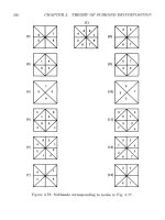
shown
in
Fig. 3.51,
and we can
write
Observe
that
the
lattice butterfly
is
simply
a 2 x 2
Hadamard matrix.
216
CHAPTER
3.
THEORY
OF
SUBBAND
DECOMPOSITION
Figure 3.51: Lattice realization
of
power complementary
filters;
AQ(Z),
A\(z)
are
all-pass networks.
3.7.2
The
Two-Band
IIR
QMF
Structure
Returning
to the
two-band
filter
structure
of
Fig. 3.20,
we can
eliminate aliasing
from
Eq.
(3.36)
by
selecting
GQ(Z)
=
HI(-Z)
and
GI(Z)
-
-H
0
(-z).
This results
in
T(z)
=
H
0
(z)H
1
(-z)
-
H
O
(-Z)H!(Z).
Now let
HI(Z)
—
HQ(—Z],
which ensures that
H\(z]
will
be
high-pass
if
H$(z]
is
low-pass.
Thus
T(z)
=
H%(z)
-
H
2
(-z)
=
H
2
(z)
-
H$(z).
Finally,
the
selection
of
HQ(Z]
and
H\(z)
by Eq.
(3.232) results
in
Thus,
T(z)
is the
product
of two
all-pass transfer functions and, therefore,
is
itself
all-pass. Some insight into
the
nature
of the
all-pass
is
achieved
by the
polyphase
representations
of the
analysis
filters,
The
all-pass networks
are
therefore
3.7.
IIR
SUBBAND
FILTER BANKS
217
These results suggest
the
two-band lattice
of
Fig. 3.52,
where
O,Q(Z)
and
a\(z)
are
both all-pass
filters.
We
can
summarize these results with
In
addition
to the
foregoing constraints,
we
also want
the
high-pass
filter to
have
zero
DC
gain
(and
correspondingly,
the
low-pass
filter
gain
to be
zero
at
u?
=
?r).
It can be
shown
that
if the filter
length
N is
even (i.e.,
filter
order
JV
—
1
is
odd),
then
NQ(Z]
has a
zero
at z
—
—
1 and
NI(Z)
has a
zero
at z =
\.
Pole-zero
patterns
for
typical
HQ(z},
H\(z]
are
shown
in
Fig. 3.53.
Figure
3.52:
Two-band power complementary all-pass
IIR
structure.
218
CHAPTER
3.
THEORY
OF
SUBBAND DECOMPOSITION
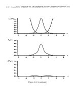
Figure 3.53: Typical
IIR
power complementary two-band
filters.
A
design procedure
as
described
in
Vaidyanathan
(Jan. 1990)
is as
follows.
Let
the
all-pass polyphase components
O,Q(Z),
a
i(
z
)
have alternating real poles
Then,
By
construction,
NQ(Z)
is a
mirror image polynomial
of odd
order
N
—
1, and
the
poles
of
HQ(Z)
are all
purely imaginary.
The set
{p^}
can
then
be
chosen
to
put the
zeros
of
A^o(^)
on the
unit circle
as
indicated
in
Fig. 3.53. Procedures
for
designing
M-band
power complementary
filters are
given
in
Vaidyanathan (Jan,
1990),
and S. R.
Filial,
Robertson,
and
Phillips (1991). (See also Prob. 3.31)
3.7.3
Perfect Reconstruction
IIR
Subband Systems
We
know
that
physically realizable (i.e., causal)
IIR filters
cannot have
a
linear-
phase. However, noncausal
IIR filters can
exhibit even symmetric impulse
re-
3.7.
IIR
SUBBAND
FILTER
BANKS
219
sponses
and
thus have
linear-phase,
in
this case, zerophase.
This suggests that noncausal
IIR filters can be
used
to
eliminate phase dis-
tortion
as
well
as
amplitude distortion
in
subbands.
One
procedure
for
achieving
a
linear-phase response uses
the
tandem connection
of
identical causal
IIR
niters
separated
by two
time-reversal operators,
as
shown
in
Fig. 3.54.
Figure
3.54: Linear-phase
IIR filter
configuration;
R is a
time-reversal.
The finite
duration input signal
x(n)
is
applied
to the
causal
IIR filter
H(z).
The
output
v(n)
is
lengthened
by the
impulse response
of the filter and
hence
in
principle
is of
infinite
duration.
In
time, this output becomes
sufficiently
small
and can be
truncated with negligible error. This truncated signal
is
then reversed
in
time
and
applied
to
H(z]
to
generate
the
signal
w(n);
this output
is
again
truncated
after
it has
become
very
small,
and
then reversed
in
time
to
yield
the
final
output
y(n).
Noting
that
the
time-reversal operator induces
we
can
trace
the
signal
transmission
through
Fig. 3.52
to
obtain
Hence,
where
The
composite transfer
function
is
\H(e^)\
2
and has
zero phase.
The
time rever-
sals
in
effect
cause
the filters to
behave like
a
cascade
of
stable
causal
and
stable
anticausal
filters.
220
CHAPTER
3.
THEORY
OF
SUBBAND DECOMPOSITION
This analysis does
not
account
for the
inherent delays
in
recording
and
revers-
ing
the
signals.
We can
account
for
these
by
multiplying
$(z)
by
Z~(
NI+N
'^,
where
N[
and
N%
represent
the
delays
in the first and
second time-reversal operators.
Kronander (ASSP, Sept.
88)
employed this idea
in his
perfect
reconstruction
two-band
structure shown
in
Fig. 3.55.
Two
time-reversals
are
used
in
each
leg
but
these
can be
distributed
as
shown,
and all
analysis
and
synthesis
filters are
causal
IIR.
Using
the
transformations induced
by
time-reversal
and up- and
down-samp-
ling,
we
can
calculate
the
output
as
The
aliasing term S(z)
can be
eliminated,
and a
low-pass/high-pass split
ob-
tained
by
choosing
This
forces
S(z]
=
0, and
T(z)
is
simply
On
the
unit circle (for real
ho(n}),
the PR
condition reduces
to
Hence,
we
need
satisfy
only
the
power complementarity requirement
of
causal
IIR
filters to
obtain perfect reconstruction!
We may
regard this last equation
as the
culmination
of the
concept
of
combining causal
IIR filters and
time-reversal oper-
ators
to
obtain linear-phase
filters, as
suggested
in
Fig. 3.54.
The
design
of
{Ho(z),
H\(z}}
IIR
pair
can
follow
standard
procedures,
as
out-
lined
in the
previous section.
We can
implement
HQ(Z)
and
H\(z)
by the
all-pass
lattice structures
as
given
by
Eqs. (3.241)
and
(3.242)
and
design
the
constituent
all-pass
filters
using standard tables (Gazsi, 1985).
3.7.
IIR
SUBBAND
FILTER
BANKS
221
Figure 3.55: Two-band
perfect
reconstruction
IIR
configuration;
R
denotes
a
time-
reversal
operator.
Figure 3.56: Two-channel
IIR
subband
configuration.
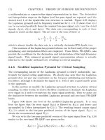
PE
means periodic exten-
sion
and WND is the
symbol
for
window.
The
second
approach
to PR IIR filter
banks
was
advanced
by
Smith
and
Eddins
(ASSP,
Aug. 1990)
for filtering finite
duration signals such
as
sequences
of
pixels
in
an
image.
A
continuing stream
of
sequences such
as
speech
is, for
practical
purposes,
infinite
in
extent.
Hence each subband channel
is
maximally decimated
at its
respective Nyquist
rate,
and the
total
number
of
input samples
equals
the
number
of
output samples
of the
analysis section.
For
images,
however,
the
con-
volution
of the
spatially limited image with each subband analysis
filter
generates
outputs whose lengths exceed
the
input extent. Hence
the
total
of all the
samples
(i.e.,
pixels)
in the
subband
output
exceeds
the
total
number
of
pixels
in the
image;
the
achievable compression
is
decreased accordingly, because
of
this overhead.
The
requirements
to be met by
Smith
and
Eddins
are
twofold:
(1)
The
analysis section should
not
increase
the
number
of
pixels
to be
encoded.
222
CHAPTEB,
3.
THEORY
OF
SUBBAND DECOMPOSITION
(2)
IIR
filters
with
PR
property
are to be
used.
The
proposed configuration
for
achieving
these objectives
is
shown
in
Fig. 3.56
as
a
two-band codec
and in
Fig. 3.57
in the
equivalent polyphase
lattice
form.
The
analysis section consists
of
low-pass
and
high-pass causal
IIR filters, and
the
synthesis section
of
corresponding
anticausal
IIR filters. The key to the
pro-
posed solution
is the
conversion
of the finite-duration
input signal
to a
periodic
one:
and the use of
circular convolution.
In the
analysis section
the
causal
IIR,
filter is
implemented
by a
difference
equation running forward
in
time over
the
periodic sig-
nal;
in the
synthesis
part,
the
anticausal
IIR filter
operates
via a
backward-running
difference
equation. Circular convolution
is
used
to
establish initial conditions
for
the
respective
difference
equations.
These
periodic
repetitions
are
indicated
by
tildes
on
each signal.
The
length
N
input
x(ri]
is
periodically extended
to
form
x(n)
in
accordance with
Eq.
(3.250).
As
indicated
in
Fig. 3.57 this signal
is
subsampled
to
give
£o(
n
)
an
d
£i(
n
))
each
of
period
N/2 (N is
assumed
to be
even).
Each subsampled periodic sequence
is
then
filtered
by
the
causal
IIR
polyphase lattice
to
produce
the N/2
point periodic
se-
quences
'Do(n)
and
vi(n).
These
are
then windowed
by an N/2
point window prior
to
encoding. Thus,
the
output
of the
analysis section consists
of two N/2
sample
sequences while
the
input x(n)
had N
samples. Maximal decimation
is
thereby
preserved. Inverse operations
are
performed
at the
synthesis side using noncausal
operators. Next,
we
show
that
this structure
is
indeed
perfect
reconstruction
and
describe
the
details
of the
operations.
For the
two-band structure,
the
perfect
reconstruction conditions
were
given
by
Eq.
(3.74), which
is
recast here
as
The
unconstrained solution
is
3.7,
IIR
SUBBAND
FILTER BANKS
223
Figure 3.57: Two-channel polyphase lattice
configuration
with causal analysis
and
anticausal
synthesis sections.
Let
us
construct
the
analysis
filters
from
all-pass
sections
and
constrain
H\(z]
=
HQ(—Z).
Thus,
we
have
the
polyphase decomposition
and
PQ(Z},
PI(Z)
are
both
all-pass.
For
this choice,
A
reduces
to
simply
The PR
conditions
are met by
224
CHAPTER
3.
THEORY
OF
SUBBAND
DECOMPOSITION
But,
for an
all-pass,
PQ(Z)PQ(Z~
I
)
— 1.
Hence
Therefore,
the PR
conditions
for the
synthesis all-pass
filters
are
simply
which
are
recognized
as
anticausal,
if the
analysis
filters are
causal.
To
illustrate
the
operation,
suppose
PQ(Z]
is first-order:
Since
the N/2
point periodic sequence
£(n)
is
given,
we can
solve
the
difference
equation
recursively
for n —
0,1,
2, ,
y
—
1. Use is
made
of the
periodic
nature
of
£(n)
so
that
terms
like
£(—1)
are
replaced
by
|(y
- 1); but we
need
an
initial
condition
«§(—!).
This
is
obtained
via the
following
steps.
The
impulse response
Po(n)
is
circularly convolved with
the
periodic input.
The
difference
equation
is
then (the subscript
is
omitted
for
simplicity)
Similarly,
we find
3.7.
im
SUBBAND FILTER BANKS
225
But
Em=o0(
m
)
can
be
written
as
EfcL^ESo^
+
MT/2).
The
sum
term
be-
comes
Finally,
This last equation
is
used
to
compute
s(—1),
the
initial condition needed
for the
difference
equation,
Eq.
(3.259).
The
synthesis side
operates
with
the
anticausal
all-pass
or
The
difference
equation
is
which
is
iterated
backward
in
time
to
obtain
the
sequence
with
starting value
f?(l)
obtained
from
the
circular convolution
of
g$(n)
and
f(n).
This
can be
shown
to be
with
226
CHAPTER
3.
THEORY
OF
SUBBAND DECOMPOSITION
The
classical advantages
of
IIR
over
FIR are
again demonstrated
in
subband
coding.
Comparable magnitude
performance
is
obtained
for a first-order
PQ(Z)
(or
fifth-order
HQ(Z}}
and a
32-tap
QMF
structure
The
computational
complexity
is
also favorable
to the IIR
structure, typically
by
factors
of 7 to 14
(Smith
and
Eddins,
1990).
3.8
Transmultiplexers
The
subband
filter
bank
or
codec
of
Fig. 3.32
is an
analysis/synthesis structure.
The
front
end or
"analysis" side performs signal decomposition
in
such
a way as to
allow
compression
for
efficient
transmission
or
storage.
The
receiver
or
"synthesis"
section reconstructs
the
signal
from
the
decomposed components.
The
transmultiplexer,
depicted
in
Fig. 3.58,
on the
other hand,
can be
viewed
as the
dual
of the
subband codec.
The
front
end
constitutes
the
synthesis
sec-
tion wherein several component signals
are
combined
to
form
a
composite signal
which
can be
transmitted
over
a
common channel.
This
composite signal could
be
any one of the
time-domain multiplexed (TDM), frequency-domain multiplexed
(FDM),
or
code division multiplexed (CDM) varieties.
At the
receiver
the
analy-
sis
filter
bank separates
the
composite signal into
its
individual components.
The
multiplexer
can
therefore
be
regarded
as a
synthesis/analysis
filterbank
structure
that
functions
as the
conceptual dual
of the
analysis/synthesis subband structure.
Figure
3.58:
Af-band
multiplexer
as a
critically sampled synthesis/analysis
mul-
tirate filterbank.
In
this
section
we
explore
this
duality between codec
and
transmux
and
show
that
perfect reconstruction
and
alias cancellation
in the
codec correspond
to
PR
and
cross-talk cancellation
in the
transmux.
3.8.
TRANSMULTIPLEXERS
227
3.8.1
TDMA, FDMA,
and
CDMA Forms
of the
Transmultiplexor
The
block diagram
of the
M-band
digital
transmultiplexer
is
shown
in
Figure 3,58.
Each signal
Xh(n]
of the
input
set
is
up-sampled
by M, and
then
filtered
by
Gk(z),
operating
at the
fast
clock rate.
This signal
|/&(n)
is
then added
to the
other components
to
form
the
composite
signal
y(n),
which
is
transmitted over
one
common channel wherein
a
unit delay
is
introduced
2
.
This
is a
multiuser scenario wherein
the
components
of
this composite
signal
could
be
TDM, FDM,
or CDM
depending
on the filter
used.
The
simplest
case
is
that
of the TDM
system. Here
each
synthesis
filter
(Gk(z)
=
z~
,
k.
—
0,1,.,.,
M—
1) is a
simple delay
so
that
the
composite signal
y(n)
is the
interleaved
signal
Figure 3.59:
Three-band
TDMA Transmultiplexer.
At
the
receiver
(or
"demux"),
the
composite
TDM
signal
is
separated
into
its
constituent components. This
is
achieved
by
feeding
the
composite signal into
a
bank
of
appropriately chosen delays,
and
then down-sampling,
as
indicated
in
Fig. 3.59
for a
three-band TDMA transmux.
For the
general case with
Gk(z)
=
z~~
k
,
0
<
k
<
M
—
1, the
separation
can be
realized
by
choosing
the
corresponding
analysis
filter to be
Insertion
of a
delay
z
l
(or
more generally
z
(
IM+1
~>
for
/
any
integer) simplifies
the
analysis
to follow and
obviates
the
need
for a
shuffle
matrix
in the
system
transfer function matrix.
228
CHAPTER,
3.
THEORY
OF
SUBBAND DECOMPOSITION
for
r
any
integer.
The
simplest
noncausal
and
causal cases correspond
to r — 0
and r
=
1,
respectively. This reconstruction results
in
just
a
simple delay.
as can be
verified
by a
study
of the
selectivity provided
by the
upsampler-delay-
down-sampler
structure shown
as
Fig. 3.60. This
is a
linear
time-invariant
system
whose
transfer
function
is
zero unless
the
delay
r is a
multiple
of M,
i.e.,
Figure 3.60: Up-sampler-delay-down-sampler structure.
In
essence,
the
TDM
A
transmux
provides
a
kind
of
time-domain
orthogonality
across
the
channels. Note that
the
impulse responses
of the
synthesis
filters
are
orthonormal
in
time. Each input sample
is
provided with
its own
time
slot,
which
does
not
overlap with
the
time slot allocated
to any
other signal.
That
is.
This represents
the
rawest kind
of
orthogonality
in
time. From
a
time-frequency
standpoint,
the
impulse response
is the
time-localized
Kronecker
delta sequence
while
the
frequency
response,
has a flat,
all-pass
frequency characteristic with linear-phase.
The filters all
overlap
in
frequency
but are
absolutely non-overlapping
in the
time domain; this
is a
pure
TDM—-+
TDM
system.
The
second scenario
is the TDM
—>FDM
system.
In
this case,
the
up-sampler
compresses
the
frequency scale
for
each signal (see Fig. 3.61).
This
is
followed
by
an
ideal,
"brick-wall,"
band-pass
filter of
width
7T/M,
which eliminates
the
images
3.8.
TRANSMULTIPLEXORS
229
and
produces
the FDM
signal occupying
a
frequency
band
ir/M.
These
FDM
signals
are
then added
in
time
or
butted together
in
frequency
with
no
overlap
and
transmitted over
a
common channel.
The
composite
FDM
signal
is
then
separated into
its
component
parts
by
band-pass,
brick-wall
filters in the
analysis
bank,
and
then down-sampled
by M so as to
occupy
the
full
frequency
band
at
the
slow
clock
rate,
An
example
for an
ideal 2-band
FDM
transmux
is
depicted
in
Figs. 3.61
and
3.62.
The FDM
transmux
is the
frequency-domain dual
of the TDM
transmux.
In
the FDM
system,
the
band-pass synthesis
filterbank
allocates
frequency
bands
or
"slots"
to the
component signals.
The FDM
signals
are
distributed
and
overlap
time,
but
occupy non-overlapping slots
in
frequency.
On the
interval
[0,
TT],
the
synthesis
filters
defined
by
{
1
b2L
< <
(fc+
1
)
7r
.
'
M
—
w
— M '
k
— 0 1 M — 1 (3
9
69)
0,
else.
'
u,i, ,M
I,
(6.M)
are
clearly orthogonal
by
virtue
of
non-overlap
in
frequency
G
k
(e?
u
)Gi(e?»)du
=
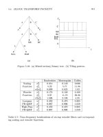
Figure 3.61: Ideal two-band TDM-FDM transmux.
HQ
and
HI
are
ideal low-pass
and
band-pass
niters.
These
filters are
localized
in
frequency
but
distributed over time,
The
time-
frequency
duality between
TDM and FDM
transmultiplexers
is
summarized
in
Table 3.3.
It
should
be
evident
at
this point
that
the
orthonormality
of a
trans-
multiplexer need
not be
confined
to
purely
TDM or FDM
varieties.
The
orthonor-
mality
and
localization
can be
distributed over both time-
and
frequency-domains,
230
CHAPTER
3.
THEORY
OF
SUBBAND DECOMPOSITION
Figure 3.62: Signal transforms
in
ideal 2-band
FDM
system transmux
of
Fig. 3.61.
3.8.
TRANSMULTIPLEXERS
231
as in
QMF
filter
banks. When this
view
is
followed,
we are led to a
consideration
of
a
broader
set of
orthonormality conditions
which
lead
to
perfect
reconstruction.
The filter
impulse responses
for
this class
are the
code-division multiple access
(CDMA)
codes
for a set of
signals. These
filter
responses
are
also
the
same
as
what
are
known
as
orthogonal spread spectrum codes.
TDM
FDM
CDM
Impulse
response
9k(n)
5(n
-
k)
1
sm(nw/2M)
(fi
a
,
1
\
rnr
i
M
TMT/2M
CC
MI
/C
1
l)
M
*
Frequency
response
G
k
(e^)
e
-jku
aii-pasg
Eq.
(3.269), band-pass
Localization
Time
Frequency
Distributed over time
and
frequency
Table 3.3: Time-frequency characteristics
of TDM and FDM
transmultiplexers.
3.8.2 Analysis
of the
Transmultiplexer
In
this section
we
show
that
the
conditions
on the
synthesis/analysis
filters
for
perfect
reconstruction
and for
cross-talk cancellation
are
identical
to
those
for PR
and
alias cancellation
in the QMF
interbank.
Using
the
polyphase equivalences
for
the
synthesis
and
analysis
filter,
we can
convert
the
structure
in
Fig. 3.58
to
the
equivalent shown
in
Fig. 3.63 where
the
notation
is
consistent with
that
used
in
connection with Figs. 3.35
and
3.36. Examination
of the
network within
the
dotted lines shows
that
there
is no
cross-band transmission,
and
that
within
each
band,
the
transmission
is a
unit delay, i.e.,
This
is
also evident
from
the
theorem implicit
in
Fig. 3.60.
Using
vector
notation
and
transforms,
we
have
Therefore,
at the
slow
clock
rate,
the
transmission
from
rj(z)
to
£(z)
is
just
a
diagonal delay matrix.
The
system within
the
dotted line
in
Fig. 3.63
can
therefore
be
replaced
by
matrix
z~
l
l
as
shown
in
Fig. 3.64. This diagram also demonstrates
that
the
multiplexer
from
slow clock
rate
input
x(n)
to
slow clock
rate
output
x(n)
is
linear, time-invariant
(LTI)
for any
polyphase matrices
Q
p
(z)^H
p
(z)
1
and
hence
is LTI for any
synthesis/analysis
filters.
This
should
be
compared with
the
analysis/synthesis codec which
is LTI at the
slow-clock
rate
(from
£(n)
to
232
CHAPTER
3.
THEORY
OF
SUBBAND
DECOMPOSITION
Figure 3.64: Reduced
polyphase
equivalent
of
transmultiplexer.
r?(n)
in
Fig. 3.36),
but is
LTI
at the
fast clock
rate
(from
x(n)
to
x(n))
only
if
aliasing
terms
are
cancelled.
The
complete analysis
of the
transmultiplexer
using
polyphase matrices
is
quite straightforward. Prom Fig. 3.64,
we see
that
For PR
with
a
unit (slow clock) delay,
we
want
Hence,
the
necessary
and
sufficient
condition
for a PR
transmultiplexer
is
simply
/"
\ /
—
J_/
\ /
\
/
Prom Eqs. (3.100)
and
(3.101),
the
corresponding condition
for PR in the QMF
filter
bank
is