Light Measurement Handbook phần 6 docx
Bạn đang xem bản rút gọn của tài liệu. Xem và tải ngay bản đầy đủ của tài liệu tại đây (537.47 KB, 13 trang )
52
Light Measurement Handbook © 1998 by Alex Ryer, International Light Inc.
53
Light Measurement Handbook © 1998 by Alex Ryer, International Light Inc.
54
Light Measurement Handbook © 1998 by Alex Ryer, International Light Inc.
55
Light Measurement Handbook © 1998 by Alex Ryer, International Light Inc.
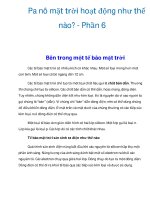
12 Choosing Input
Optics
When selecting input optics for a measurement
application, consider both the size of the source and the
viewing angle of the intended real-world receiver.
Suppose, for example, that you were measuring
the erythemal (sunburn) effect of the sun on human skin.
While the sun may be considered very much a point
source, skylight, refracted and reflected by the
atmosphere, contributes significantly to the overall
amount of light reaching the earth’s surface. Sunlight
is a combination of a point source and a 2π steradian
area source.
The skin, since it is relatively flat and diffuse, is
an effective cosine receiver. It absorbs radiation in
proportion to the incident angle of the light. An
appropriate measurement system should also have a
cosine response. If you aimed the detector directly at
the sun and tracked the sun's path, you would be
measuring the maximum irradiance. If, however, you
wanted to measure the effect on a person laying on the
beach, you might want the detector to face straight up,
regardless of the sun’s position.
Different measurement geometries necessitate
specialized input optics. Radiance and luminance
measurements require a narrow viewing angle
(< 4°) in order to satisfy the conditions underlying
the measurement units. Power measurements, on
the other hand, require a uniform response to
radiation regardless of input angle to capture all
light.
There may also be occasions when the need
for additional signal or the desire to exclude off-
angle light affects the choice of input optics. A
high gain lens, for example, is often used to amplify a
distant point source. A detector can be calibrated to use any
input optics as long as they reflect the overall goal of the measurement.
56
Light Measurement Handbook © 1998 by Alex Ryer, International Light Inc.
Cosine Diffusers
A bare silicon cell has a near perfect cosine response, as do all diffuse
planar surfaces. As soon as you place a filter in front of the detector, however,
you change the spatial
responsivity of the cell by
restricting off-angle
light.
Fused silica or
optical quartz with a
ground (rough) internal
hemisphere makes an
excellent diffuser with
adequate transmission in
the ultraviolet. Teflon is
an excellent alternative
for UV and visible
applications, but is not an
effective diffuser for infrared light. Lastly, an integrating sphere coated with
BaSO
4
or PTFE powder is the ideal cosine receiver, since the planar sphere
aperture defines the cosine relationship.
57
Light Measurement Handbook © 1998 by Alex Ryer, International Light Inc.
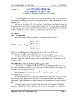
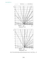
Radiance Lens Barrels
Radiance and luminance optics
frequently employ a dual lens system
that provides an effective viewing
angle of less than 4°. The tradeoff of
a restricted viewing angle is a
reduction in signal. Radiance optics
merely limit the viewing angle to less
than the extent of a uniform area
source. For very small sources, such
as a single element of an LED display,
microscopic optics are required to
“underfill” the source.
The Radiance barrel shown at
right has a viewing angle of 3°, but due
to the dual lenses, the extent of the
beam is the full diameter of the first
lens; 25 mm. This provides increased
signal at close distances, where a
restricted viewing angle would limit
the sampled area.
58
Light Measurement Handbook © 1998 by Alex Ryer, International Light Inc.
Fiber Optics
Fiber optics allow measurements in
tight places or where irradiance levels and
heat are very high. Fiber optics consist of a
core fiber and a jacket with an index of
refraction chosen to maximize total internal
reflection. Glass fibers are suitable for use
in the visible, but quartz or fused silica is
required for transmission in the ultraviolet.
Fibers are often used to continuously monitor
UV curing ovens, due to the attenuation and
heat protection they provide. Typical fiber
optics restrict the field of view to about ±20°
in the visible and ±10° in the ultraviolet.
Integrating Spheres
An integrating sphere is a hollow
sphere coated inside with Barium Sulfate, a
diffuse white reflectance coating that offers
greater than 97% reflectance between 450
and 900 nm. The sphere is baffled internally
to block direct and first-bounce light.
Integrating spheres are used as sources of
uniform radiance and as input optics for
measuring total power. Often, a lamp is place
inside the sphere to capture light that is
emitted in any direction.
High Gain Lenses
In situations with low irradiance from
a point source, high gain input optics can be
used to amplify the light by as much as 50
times while ignoring off angle ambient light.
Flash sources such as tower beacons often
employ fresnel lenses, making near field
measurements difficult. With a high gain
lens, you can measure a flash source from a
distance without compromising signal
strength. High gain lenses restrict the field
of view to ±8°, so cannot be used in full
immersion applications where a cosine
response is required.
59
Light Measurement Handbook © 1998 by Alex Ryer, International Light Inc.
13 Choosing a
Radiometer
Detectors translate light energy into an electrical current. Light striking
a silicon photodiode causes a charge to build up between the internal "P" and
"N" layers. When an external circuit is connected to the cell, an electrical
current is produced. This current is linear with respect to incident light over a
10 decade dynamic range.
A wide dynamic range is a prerequisite for most applications. The
radiometer should be able to cover the entire dynamic range of any detector
that will be plugged into it. This
usually means that the
instrument should be able to
cover at least 7 decades of
dynamic range with minimal
linearity errors. The current or
voltage measurement device
should be the least significant
source of error in the system.
The second thing to
consider when choosing a radiometer is the type of features offered. Ambient
zeroing, integration ability, and a “hold” button should be standard. The ability
to multiplex several detectors to a single radiometer or control
the instrument remotely may also be desired for certain
applications. Synchronous detection capability may be
required for low level signals. Lastly, portability and
battery life may be an issue for measurements made in
the field.
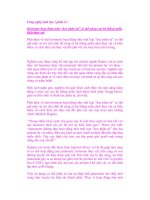
Billion-to-One Dynamic Range
Sunny Day 100000. lux
Office Lights 100. lux
Full Moon 0.1 lux
Overcast Night 0.0001 lux
60
Light Measurement Handbook © 1998 by Alex Ryer, International Light Inc.
Floating Current to Current Amplification
International Light radiometers amplify current using a floating current-
to-current amplifier (FCCA), which mirrors and boosts the input current
directly while “floating” completely isolated. The FCCA current amplifier
covers an extremely large dynamic range without changing gain. This
proprietary amplification technique is the key to our unique analog to digital
conversion, which would be impossible without linear current preamplification.
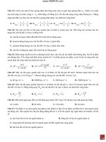
We use continuous wave integration to integrate (or sum) the incoming
amplified current as a charge, in a capacitor. When the charge in the capacitor
reaches a threshold, a charge packet is released. This is
analogous to releasing a drop from an eye dropper.
Since each drop is an identical known volume,
we can determine the total volume by counting the
total number of drops. The microprocessor simply
counts the number of charge packets that are released
every 500 milliseconds. Since the clock speed of
the computer is much faster than the release of charge
packets, it can measure as many as 5 million, or as few
as 1 charge packet, each 1/2 second. On the very low end,
we use a rolling average to enhance the resolution by a
factor of 4, averaging over a 2 second period. The instrument
can cover 6 full decades without any physical gain
change!
In order to boost the dynamic range even further, we
use a single gain change of 1024 to overlap two 6 decade
ranges by three decades, producing a 10 decade dynamic
range. This “range hysteresis” ensures that the user
remains in the middle of one of the working ranges without the
need to change gain. In addition, the two ranges are locked
together at a single point, providing a step free transition
between ranges. Even at a high signal level, the instrument is
still sensitive to the smallest charge packet, for a resolution of 21
bits within each range! With the 10 bit gain change, we overlap two
21 bit ranges to achieve a 32 bit Analog to Digital conversion,
yielding valid current measurements from a resolution of 100
femtoamps (10
-13
A) to 2.0 milliamps (10
-3
A). The linearity of the instrument
over its entire dynamic range is guaranteed, since it is dependent only on the
microprocessor's ability to keep track of time and count, both of which it does
very well.
61
Light Measurement Handbook © 1998 by Alex Ryer, International Light Inc.
Transimpedance Amplification
Transimpedance amplification is the most common type of signal
amplification, where an op-amp and feedback resistor are employed to amplify
an instantaneous current. Transimpedance amplifiers are excellent for
measuring within a fixed decade range, but must change gain by switching
feedback resistors in order to handle higher or lower signal levels. This gain
change introduces significant errors between ranges, and precludes the
instrument from measuring continuous exposures.
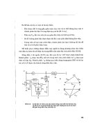
A graduated cylinder is a good analogy for describing some of the
limitations of transimpedance amplification. The graduations on the side of
the cylinder are the equivalent of bit depth in an A-D
converter. The more graduating lines, the
greater the resolution in the measurement. A beaker
cannot measure volumes greater than itself, and
lacks the resolution for smaller measurements. You
must switch to a different size container to expand the
measurement range - the equivalent of changing gain
in an amplifier.
In a simple light meter, incoming light induces a
voltage, which is amplified and converted to digital
using an analog-to-digital converter. A 10 bit A-D
converter provides a total of 1024 graduations between 0
and 1 volt, allowing you to measure between 100 and
1000 to an accuracy of 3 significant digits. To
measure between 10 and 100, however, you must
boost the gain by a factor of 10, because the resolution
of the answer is only two digits. Similarly, to
measure between 1 and 10 you must boost the gain by
a factor of 100 to get three digit resolution again.
In transimpedance systems, the 100% points
for each range have to be adjusted and set to an
absolute standard. It is expected for a mismatch to
occur between the 10% point of one range and the 100%
point of the range below it. Any nonlinearity or zero
offset error is magnified at this 10% point.
Additionally, since voltage is sampled instantaneously, it
suffers from a lower S/N ratio than an integrating amplifier. Transimpedance
amplifiers simulate integration by taking multiple samples and calculating
the average reading. This technique is sufficient if the sampling rate is at
least double the frequency of the measured signal.
62
Light Measurement Handbook © 1998 by Alex Ryer, International Light Inc.
Integration
The ability to sum all of the incident light over a period of time is a very
desirable feature. Photographic film is a good example of a simple integration.
The image on the emulsion becomes more intense the longer the exposure
time. An integrating radiometer sums the irradiance it measures continuously,
providing an accurate measure of the total exposure despite possible changes
in the actual irradiance level.
The primary difficulty most radiometers have with integration is range
changes. Any gain changes in the amplification circuitry mean a potential
loss of data. For applications with relatively constant irradiance, this is not a
concern. In flash integration, however, the change in irradiance is dramatic
and requires specialized amplification circuitry for an accurate reading.
Flash integration is preferable to measuring the peak irradiance, because
the duration of a flash is as important as its peak. In addition, since the total
power from a flash is low, an integration of 10 flashes or more will significantly
improve the signal to noise ratio and give an accurate average flash. Since
International Light radiometers can cover a large dynamic range (6 decades
or more) without changing gain, the instruments can accurately subtract a
continuous low level ambient signal while catching an instantaneous flash
without saturating the detector.
The greatest benefit of integration is that it cancels out noise. Both the
signal and the noise vary at any instant in time, although they are presumably
constant in the average. International Light radiometers integrate even in
signal mode, averaging over a 0.5 second sampling period to provide a
significant improvement in signal to noise ratio.
Zero
The ability to subtract ambient light and noise from readings is a
necessary feature for any radiometer. Even in the darkest room, electrical
“dark current” in the photodiode must be subtracted. Most radiometers offer
a “Zero” button that samples the ambient scatter and electrical noise,
subtracting it from subsequent readings.
Integrated readings require ambient subtraction as well. In flash
measurements especially, the total power of the DC ambient could be higher
than the power from an actual flash. An integrated zero helps to overcome
this signal to noise dilemma.
63
Light Measurement Handbook © 1998 by Alex Ryer, International Light Inc.
14 Calibration
“NIST-traceable” metrology labs purchase calibrated transfer standard
detectors directly from the National Institute of Standards and Technology in
Gaithersburg, MD. From 400 to 1100 nm, this transfer standard is a
Hamamatsu S1337-1010BQ photodiode, a 10 x 10 mm planar silicon cell
coated with synthetic quartz. The photodiode is mounted behind a precisely
measured 7.98 mm diameter circular aperture, yielding an active area of 0.5
cm2. The responsivity is usually given every 5 nanometers.
The calibration labs then use this transfer standard to calibrate their
intercomparison working standards using a monochromatic light source. These
working standards are typically identical to the equipment that will be
calibrated. The standards are rotated in the lab, tracked over time to monitor
stability, and periodically recalibrated.
Detectors are most often calibrated at the peak wavelength of the detector
/ filter / diffuser combination using identical optics for the intended application.
The key to this calibration transfer is a reliable kinematic mount that allows
exchangeability of detectors in the optical path, and a stable, power regulated
light source. Complete spectroradiometric responsivity scans or calibration
at an alternate wavelength may be preferred in certain circumstances.
Although the working standard and the unknown detector are fixed in
precise kinematic mounts in front of carefully regulated light sources, slight
errors are expected due to transfer error and manufacturing tolerances. An
overall uncertainty to absolute of 10% or less is considered very good for
radiometry equipment, and is usually only achievable by certified metrology
labs. An uncertainty of 1% is considered state of the art, and can only be
achieved by NIST itself.
64
Light Measurement Handbook © 1998 by Alex Ryer, International Light Inc.
References
American Conference of Governmental Industrial Hygienists. (1992). Threshold
Limit Values and Biological Exposure Indices. (2nd printing). Cincinnati,
OH: Author.
Ballard, S. B., Slack, E. P., & Hausmann, E. (1954). Physics Principles. New
York: D. Van Nostrand Company.
Bartleson, C. J. & Grum, F. (Eds.). (1984). Optical Radiation Measurements: Vol.
5. Visual Measurements. Orlando, FL: Academic Press.
Budde, W. (1983). Optical Radiation Measurements: Vol. 4. Physical Detectors
of Optical Radiation. Orlando, FL: Academic Press.
Commission Internationale de l’Eclairage. (1985). Methods of Characterizing
Illuminance Meters and Luminance Meters. [Publication #69] CIE.
Grum, F. & Bartleson, C. J. (Eds.). (1980). Optical Radiation Measurements: Vol.
2. Color Measurement. New York: Academic Press.
Grum, F. & Becherer, R. J. (1979). Optical Radiation Measurements: Vol. 1.
Radiometry. San Diego: Academic Press.
Kingslake, R. (1965). Applied Optics and Optical Engineering. New York:
Academic Press.
Kostkowski, H. J. (1997). Reliable Spectroradiometry. La Plata, MD:
Spectroradiometry Consulting.
Mielenz, K. D. (Ed.). (1982). Optical Radiation Measurements: Vol. 3.
Measurement of Photoluminescence. Orlando, FL: Academic Press.
Ohno, Y. (1997). NIST Measurement Services: Photometric Calibrations. [NIST
Special Publication 250-37]. Gaithersburg, MD: NIST Optical Technology
Division.
Rea, M. S. (Ed.). (1993). Lighting Handbook (8th ed.). New York: Illuminating
Engineering Society of North America.
Ryer, A. D. (1996). Light Measurement Handbook [On-line] Available: http://
www.intl-light.com/handbook/
Ryer, D. V. (1997). Private communication.
Smith, W. J. (1966). Modern Optical Engineering. New York: McGraw Hill.
Stimson, A. (1974). Photometry and Radiometry for Engineers. New York: John
Wiley & Sons.
Wyszecki, G. & Stiles, W. S. (1967). Color Science. New York: John Wiley &
Sons.