Light Measurement Handbook phần 4 doc
Bạn đang xem bản rút gọn của tài liệu. Xem và tải ngay bản đầy đủ của tài liệu tại đây (239.21 KB, 10 trang )
31
Light Measurement Handbook © 1998 by Alex Ryer, International Light Inc.
Photopic Photopic Scotopic Scotopic
λ Luminous lm / W Luminous lm / W
nm Efficiency Conversion Efficiency Conversion
380 0.000039 0.027 0.000589 1.001
390 .000120 0.082 .002209 3.755
400 .000396 0.270 .009290 15.793
410 .001210 0.826 .034840 59.228
420 .004000 2.732 .096600 164.220
430 .011600 7.923 .199800 339.660
440 .023000 15.709 .328100 557.770
450 .038000 25.954 .455000 773.500
460 .060000 40.980 .567000 963.900
470 .090980 62.139 .676000 1149.200
480 .139020 94.951 .793000 1348.100
490 .208020 142.078 .904000 1536.800
500 .323000 220.609 .982000 1669.400
507 .444310 303.464 1.000000 1700.000
510 .503000 343.549 .997000 1694.900
520 .710000 484.930 .935000 1589.500
530 .862000 588.746 .811000 1378.700
540 .954000 651.582 .650000 1105.000
550 .994950 679.551 .481000 817.700
555 1.000000 683.000 .402000 683.000
560 .995000 679.585 .328800 558.960
570 .952000 650.216 .207600 352.920
580 .870000 594.210 .121200 206.040
590 .757000 517.031 .065500 111.350
600 .631000 430.973 .033150 56.355
610 .503000 343.549 .015930 27.081
620 .381000 260.223 .007370 12.529
630 .265000 180.995 .003335 5.670
640 .175000 119.525 .001497 2.545
650 .107000 73.081 .000677 1.151
660 .061000 41.663 .000313 0.532
670 .032000 21.856 .000148 0.252
680 .017000 11.611 .000072 0.122
690 .008210 5.607 .000035 .060
700 .004102 2.802 .000018 .030
710 .002091 1.428 .000009 .016
720 .001047 0.715 .000005 .008
730 .000520 0.355 .000003 .004
740 .000249 0.170 .000001 .002
750 .000120 0.082 .000001 .001
760 .000060 0.041
770 .000030 0.020
32
Light Measurement Handbook © 1998 by Alex Ryer, International Light Inc.
Irradiance and Illuminance:
Irradiance is a measure of radiometric flux per unit area, or flux density.
Irradiance is typically expressed in W/cm
2
(watts per square centimeter) or
W/m
2
(watts per square meter).
Illuminance is a measure of photometric flux per unit area, or visible
flux density. Illuminance is typically expressed in lux (lumens per square
meter) or foot-candles (lumens per square foot).
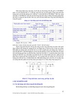
In figure 7.4, above, the lightbulb is producing 1 candela. The candela
is the base unit in light measurement, and is defined as follows: a 1 candela
light source emits 1 lumen per steradian in all directions (isotropically). A
steradian is defined as the solid angle which, having its vertex at the center of
the sphere, cuts off an area equal to the square of its radius. The number of
steradians in a beam is equal to the projected area divided by the square of the
distance.
So, 1 steradian has a projected area of 1 square meter at a distance of 1
meter. Therefore, a 1 candela (1 lm/sr) light source will similarly produce 1
lumen per square foot at a distance of 1 foot, and 1 lumen per square meter at
1 meter. Note that as the beam of light projects farther from the source, it
expands, becoming less dense. In fig. 7.4, for example, the light expanded
from 1 lm/ft
2
at 1 foot to 0.0929 lm/ft
2
(1 lux) at 3.28 feet (1 m).
Cosine Law
Irradiance measurements should be made facing the source, if possible.
The irradiance will vary with respect to the cosine of the angle between the
optical axis and the normal to the detector.
33
Light Measurement Handbook © 1998 by Alex Ryer, International Light Inc.
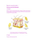
Calculating Source Distance
Lenses will distort the position of a point source. You can solve for the
virtual origin of a source by measuring irradiance at two points and solving
for the offset distance, X, using the Inverse Square Law:
E
1
(d
1
+ X)
2
= E
2
(d
2
+ X)
2
Figure 7.5 illustrates a typical setup to determine the location of an
LED’s virtual point source (which is behind the LED due to the built-in lens).
Two irradiance measurements at known distances from a reference point are
all that is needed to calculate the offset to the virtual point source.
Units Conversion: Flux Density
IRRADIANCE:
1 W/cm
2
(watts per square centimeter)
= 10
4
W/m
2
(watts per square meter)
= 6.83 x 10
6
lux at 555 nm
= 14.33 gram*calories/cm
2
/minute
ILLUMINANCE:
1 lm/m
2
(lumens per square meter)
= 1 lux (lx)
= 10
-4
lm/cm
2
= 10
-4
phot (ph)
= 9.290 x 10
-2
lm/ft
2
= 9.290 x 10
-2
foot-candles (fc)
34
Light Measurement Handbook © 1998 by Alex Ryer, International Light Inc.
Radiance and Luminance:
Radiance is a measure of the flux density per unit solid viewing angle,
expressed in W/cm
2
/sr. Radiance is independent of distance for an extended
area source, because the sampled area increases with distance, cancelling
inverse square losses.
The radiance, L, of a diffuse (Lambertian) surface is related to the radiant
exitance (flux density), M, of a surface by the relationship:
L = M / p
Some luminance units (asb, L, fL) already contain π in the denominator,
allowing simpler conversion to illuminance units.
Example
: Suppose a diffuse surface with a reflectivity, ρ,
of 85% is exposed to an illuminance, E, of 100.0 lux (lm/
m
2
) at the plane of the surface. What would be the
luminance, L, of that surface, in cd/m
2
?
Solution
:
1.) Calculate the luminous exitance of the surface:
M = E
*
ρ
M = 100.0
*
0.85 = 85.0 lm/m
2
2.) Calculate the luminance of the surface:
L = M / π
L = 85.0 / π = 27.1 lm/m
2
/sr = 27.1 cd/m
2
35
Light Measurement Handbook © 1998 by Alex Ryer, International Light Inc.
Irradiance From An Extended Source:
The irradiance, E, at any distance from a uniform extended area source,
is related to the radiance, L, of the source by the following relationship, which
depends only on the subtended central viewing angle, θ, of the radiance
detector:
E = p L sin
2
(q/2)
So, for an extended source with a radiance of 1 W/cm
2
/sr, and a detector
with a viewing angle of 3°, the irradiance at any distance would be 2.15x10
-3
W/cm
2
. This assumes, of course, that the source extends beyond the viewing
angle of the detector input optics.
Units Conversion: Radiance & Luminance
RADIANCE:
1 W/cm
2
/sr (watts per sq. cm per steradian)
= 6.83 x 10
6
lm/m
2
/sr at 555 nm
= 683 cd/cm
2
at 555 nm
LUMINANCE:
1 lm/m
2
/sr (lumens per sq. meter per steradian)
= 1 candela/m
2
(cd/m
2
)
= 1 nit
= 10
-4
lm/cm
2
/sr
= 10
-4
cd/cm
2
= 10
-4
stilb (sb)
= 9.290 x 10
-2
cd/ft
2
= 9.290 x 10
-2
lm/ft
2
/sr
= π apostilbs (asb)
= π cd/π/m
2
= π x 10
-4
lamberts (L)
= π x 10
-4
cd/π/cm
2
= 2.919 x 10
-1
foot-lamberts (fL)
= 2.919 x 10
-1
lm/π/ft
2
/sr
36
Light Measurement Handbook © 1998 by Alex Ryer, International Light Inc.
Radiant and Luminous Intensity:
Radiant Intensity is a measure of radiometric power per unit solid angle,
expressed in watts per steradian. Similarly, luminous intensity is a measure
of visible power per solid angle, expressed in candela (lumens per steradian).
Intensity is related to irradiance by the inverse square law, shown below in an
alternate form:
I = E
*
d
2
If you are wondering how the units cancel to get flux/sr from flux/area
times distance squared, remember that steradians are a dimensionless quantity.
Since the solid angle equals the area divided by the square of the radius,
d
2
=A/W, and substitution yields:
I = E
*
A / W
The biggest source of confusion regarding intensity measurements
involves the difference between Mean Spherical Candela and Beam Candela,
both of which use the candela unit (lumens per steradian). Mean spherical
measurements are made in an integrating sphere, and represent the total output
in lumens divided by 4π sr in a sphere. Thus, a one candela isotropic lamp
produces one lumen per steradian.
Beam candela, on the other hand, samples a very narrow angle and is
only representative of the lumens per steradian at the peak intensity of the
beam. This measurement is frequently misleading, since the sampling angle
need not be defined.
37
Light Measurement Handbook © 1998 by Alex Ryer, International Light Inc.
Suppose that two LED’s each emit 0.1 lm total in a narrow beam: One
has a 10° solid angle and the other a 5° angle. The 10° LED has an intensity
of 4.2 cd, and the 5° LED an intensity of 16.7 cd. They both output the same
total amount of light, however - 0.1 lm.
A flashlight with a million candela beam sounds very bright, but if its
beam is only as wide as a laser beam, then it won’t be of much use. Be wary
of specifications given in beam candela, because they often misrepresent the
total output power of a lamp.
Units Conversion: Intensity
RADIANT INTENSITY:
1 W/sr (watts per steradian)
= 12.566 watts (isotropic)
= 4
*
π W
= 683 candela at 555 nm
LUMINOUS INTENSITY:
1 lm/sr (lumens per steradian)
= 1 candela (cd)
= 4
*
π lumens (isotropic)
= 1.464 x 10
-3
watts/sr at 555 nm
38
Light Measurement Handbook © 1998 by Alex Ryer, International Light Inc.
Converting Between Geometries
Converting between geometry-based measurement units is difficult, and
should only be attempted when it is impossible to measure in the actual desired
units. You must be aware of what each of the measurement geometries
implicitly assumes before you can convert. The example below shows the
conversion between lux (lumens per square meter) and lumens.
Example
: You measure 22.0 lux from a light bulb at a
distance of 3.162 meters. How much light, in lumens, is
the bulb producing? Assume that the clear enveloped
lamp is an isotropic point source, with the exception that
the base blocks a 30° solid angle.
Solution
:
1.) Calculate the irradiance at 1.0 meter:
E
1
= (d
2
/ d
1
)
2
*
E
2
E
1.0 m
= (3.162 / 1.0)
2
*
22.0 = 220 lm/m
2
2.) Convert from lm/m
2
to lm/sr at 1.0 m:
220 lm/m
2
* 1 m
2
/sr = 220 lm/sr
3.) Calculate the solid angle of the lamp:
W = A / r
2
= 2πh / r = 2π[1 - cos(α / 2)]
W = 2π[1 - cos(330 / 2)] = 12.35 sr
4.) Calculate the total lumen output:
220 lm/sr
*
12.35 sr = 2717 lm
39
Light Measurement Handbook © 1998 by Alex Ryer, International Light Inc.
8 Setting Up An
Optical Bench
A Baffled Light Track
The best light measurement setup controls as many variables as possible.
The idea is to prevent the measurement environment from influencing the
measurement. Otherwise, the measurement will not be repeatable at a different
time and place.
Baffles, for example, greatly reduce the influence of stray light
reflections. A baffle is simply a sharp edged hole in a piece of thin sheet
metal that has been painted black. Light outside of the optical beam is blocked
and absorbed without affecting the optical path.
Multiple baffles are usually required in order to guarantee that light is
trapped once it strikes a baffle. The best light trap of all, however, is empty
space. It is a good idea to leave as much space between the optical path and
walls or ceilings as is practical. Far away objects make weak reflective sources
because of the Inverse Square Law. Objects that are near to the detector,
however, have a significant effect, and should be painted with “black velvet”
paint or moved out of view.
Closing a shutter, door, or light trap in one of the baffles allows you to
measure the background scatter component and subtract it from future readings.
The “zero” reading should be made with the source on, to maintain the
operating temperature of the lamp as well as measure light that has defeated
your baffling scheme.
40
Light Measurement Handbook © 1998 by Alex Ryer, International Light Inc.
Kinematic Mounts
Accurate distance measurements and repeatable positioning in the optical
path are the most important considerations when setting up an optical bench.
The goal of an optical bench is to provide repeatability. It is not enough to
merely control the distance to the source, since many sources have non-uniform
beams. A proper detector mounting system provides for adjustment of position
and angle in 3-D space, as well as interchangeability into a calibrated position
in the optical path.
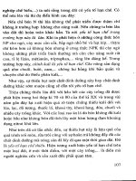
To make a kinematic fixture, cut a cone and a conical slot into a piece of
metal using a 45° conical end mill (see fig. 8.2). A kinematic mount is a three
point fixture, with the third point being any planar face. The three mounting
points can be large bolts that have been machined into a ball on one end, or
commercially available 1/4-80 screws with ball bearing tips (from Thorlabs,
Inc.) for small fixtures.
The first leg rests in the cone hole, fixing the
position of that leg as an X-Y point. The ball tip
ensures that it makes reliable, repeatable contact
with the cone surface. The second leg sits in
the conical slot, fixed only in Yaw, or
angle in the horizontal plane.
The use of a slot prevents the Yaw leg from competing with the X-Y leg for
control. The third leg rests on any flat horizontal surface, fixing the Pitch, or
forward tilt, of the assembly.
A three legged detector carrier sitting on a kinematic mounting plate is
the most accurate way to interchange detectors into the optical path, allowing
intercomparisons between two or more detectors.