Light Measurement Handbook phần 3 pdf
Bạn đang xem bản rút gọn của tài liệu. Xem và tải ngay bản đầy đủ của tài liệu tại đây (370.5 KB, 10 trang )
21
Light Measurement Handbook © 1998 by Alex Ryer, International Light Inc.
5 Light Sources
Blackbody Radiation
22
Light Measurement Handbook © 1998 by Alex Ryer, International Light Inc.
Incandescent Sources
%
%
23
Light Measurement Handbook © 1998 by Alex Ryer, International Light Inc.
Luminescent Sources
24
Light Measurement Handbook © 1998 by Alex Ryer, International Light Inc.
Sunlight
25
Light Measurement Handbook © 1998 by Alex Ryer, International Light Inc.
6 Basic
Principles
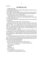
The Inverse Square Law
The inverse square law defines the relationship between the irradiance
from a point source and distance. It states that the intensity per unit area
varies in inverse proportion to the square of the distance.
E = I / d
2
In other words, if you measure 16 W/cm
2
at 1 meter, you will measure 4
W/cm
2
at 2 meters, and can calculate the irradiance at any other distance. An
alternate form is often more convenient:
E
1
d
1
2
= E
2
d
2
2
Distance is measured to the first luminating surface - the filament of a
clear bulb, or the glass envelope of a frosted bulb.
Example
: You measure 10.0 lm/m
2
from a light bulb at
1.0 meter. What will the flux density be at half the
distance?
Solution
:
E
1
= (d
2
/ d
1
)
2
* E
2
E
0.5 m
= (1.0 / 0.5)
2
* 10.0 = 40 lm/m
2
26
Light Measurement Handbook © 1998 by Alex Ryer, International Light Inc.
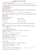
Point Source Approximation
The inverse square law can only be used in cases where the light source
approximates a point source. A general rule of thumb to use for irradiance
measurements is the “five times rule”: the distance to a light source should
be greater than five times the largest dimension of the source. For a clear
enveloped lamp, this may be the length of the filament. For a frosted light
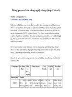
bulb, the diameter is the largest dimension. Figure 6.2 below shows the
relationship between irradiance and the ratio of distance to source radius.
Note that for a distance 10 times the source radius (5 times the diameter), the
error from using the inverse square is exactly 1 %, hence the “five times”
approximation.
Note also, that when the ratio of distance to source radius decreases to
below 0.1 (1/20 the diameter of the source), changes in distance hardly affect
the irradiance (< 1 % error). This is due to the fact that as the distance from
the source decreases, the detector sees less area, counteracting the inverse
square law. The graph above assumes a cosine response. Radiance detectors
restrict the field of view so that the d/r ratio is always low, providing
measurements independent of distance.
27
Light Measurement Handbook © 1998 by Alex Ryer, International Light Inc.
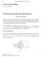
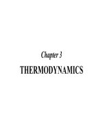
Lambert’s Cosine Law
The irradiance or illuminance falling on any surface varies as the cosine
of the incident angle, θ. The perceived measurement area orthagonal to the
incident flux is reduced at oblique angles, causing light to spread out over a
wider area than it would if perpendicular to the measurement plane.
To measure the amount of light
falling on human skin, you need to mimic
the skin’s cosine response. Since filter
rings restrict off-angle light, a cosine
diffuser must be used to correct the
spatial responsivity. In full immersion
applications like the phototherapy booth
shown above, off angle light is
significant, requiring accurate cosine
correction optics.
28
Light Measurement Handbook © 1998 by Alex Ryer, International Light Inc.
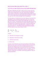
Lambertian Surface
A Lambertian surface provides uniform diffusion of the incident radiation
such that its radiance or
luminance is the same in all
directions from which it can be
measured. Many diffuse surfaces
are, in fact, Lambertian. If you
view this Light Measurement
Handbook from an oblique angle,
it should look as bright as it did
when held perpendicular to your
line of vision. The human eye,
with its restricted solid viewing
angle, is an ideal luminance, or
brightness, detector.
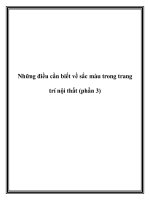
Figure 6.4 shows a surface
radiating equally at 0° and at 60°.
Since, by the cosine law, a radiance detector sees twice as much surface area
in the same solid angle for the 60° case, the average incremental reflection
must be half the magnitude of the reflection in the 0° case.
Figure 6.5 shows that a reflection
from a diffuse Lambertian surface obeys
the cosine law by distributing reflected
energy in proportion to the cosine of the
reflected angle.
A Lambertian surface that has a
radiance of 1.0 W/cm
2
/sr will radiate a
total of π*A watts, where A is the area
of the surface, into a hemisphere of 2π
steradians. Since the radiant exitance
of the surface is equal to the total power
divided by the total area, the radiant
exitance is π W/cm
2
. In other words, if
you were to illuminate a surface with
an irradiance of 3.1416 W/cm
2
, then you
will measure a radiance on that surface of 1.00 W/cm
2
/sr (if it is 100%
reflective).
The next section goes into converting between measurement geometries
in much greater depth.
29
Light Measurement Handbook © 1998 by Alex Ryer, International Light Inc.
7 Measurement
Geometries
Solid Angles
One of the key concepts to understanding the relationships between
measurement geometries is that of the solid angle, or steradian. A sphere
contains 4π steradians. A steradian is defined as the
solid angle which, having its vertex at the center
of the sphere, cuts off a spherical surface
area equal to the square of the radius of the
sphere. For example, a one s t e r a d i a n
section of a one meter radius
sphere subtends a s p h erical
surface area of one square
meter.
The sphere shown in cross
section in figure 7.1 illustrates
the concept. A cone with a solid
angle of one steradian has
been removed from the sphere. This
removed cone is shown in figure 7.2. The
solid angle, Ω, in steradians, is equal to the spherical
surface area, A, divided by the
square of the radius, r.
Most radiometric measurements do not
require an accurate calculation of the spherical
surface area to convert between units. Flat area
estimates can be substituted for spherical area when
the solid angle is less than 0.03 steradians, resulting
in an error of less than one percent. This roughly
translates to a distance at least 5 times greater than
the largest dimension of the detector. In general, if
you follow the “five times rule” for approximating
a point source (see Chapter 6), you can safely
estimate using planar surface area.
30
Light Measurement Handbook © 1998 by Alex Ryer, International Light Inc.
Radiant and Luminous Flux
Radiant flux is a measure of radiometric power. Flux, expressed in
watts, is a measure of the rate of energy flow, in joules per second. Since
photon energy is inversely proportional to
wavelength, ultraviolet photons are more
powerful than visible or infrared.
Luminous flux is a measure of
the power of visible light.
Photopic flux, expressed in
lumens, is weighted to match the
responsivity of the human eye,
which is most sensitive to yellow-
green.
Scotopic flux is weighted to
the sensitivity of the human eye in
the dark adapted state.
Units Conversion: Power
RADIANT FLUX:
1 W (watt)
= 683.0 lm at 555 nm
= 1700.0 scotopic lm at 507 nm
1 J (joule)
= 1 W*s (watt * second)
= 10
7
erg
= 0.2388 gram * calories
LUMINOUS FLUX:
1 lm (lumen)
= 1.464 x 10
-3
W at 555 nm
= 1/(4π) candela (only if isotropic)
1 lm*s (lumen * seconds)
= 1 talbot (T)
= 1.464 x 10
-3
joules at 555 nm