Embedded FreeBSD Cookbook phần 9 ppsx
Bạn đang xem bản rút gọn của tài liệu. Xem và tải ngay bản đầy đủ của tài liệu tại đây (119.71 KB, 26 trang )
186 Embedded FreeBSD
Cookbook
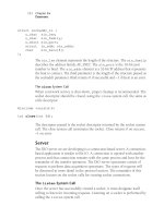
State
The first entr
y in the partition is the state, which is either value 0 or 80H.
A value of 80H denotes that this partition is active and can be booted.
Start of partition
The next thr
ee bytes contain the start of the partition in head, sector, cylinder
format. Disks traditionally access storage by head, cylinder and sector offset.
With the constant increase in capacity of hard drives, the space reserved in
the MBR became too small to address a complete hard drive. To handle this
issue, a new addressing scheme was developed that used the bits in the
head, cylinder and sector fields. This new scheme is called Logical Block
Addressing (LBA).
Let’s look at an example using the start of the partition offset 2, the sector,
and 3, the cylinder. The address of the starting sector is computed using the
offsets 2 and 3 from the partition table and a few bitwise operations.
Cylinder = (Offset(3) | ((Offset(2) & C0H) << 2);
Sector = Offset(2) & 3FH;
Start = Cylinder | Sector;
The address of the sector is computed by combining all 8 bits of the cylin-
der contained in offset 3 with the upper 2 bits of the sector value. These 10
bits contain the upper 10 bits of the address of the sector. The lower 6 bits
of the sector in offset 2 contain the sector within the cylinder. The address
is the combination of the computed
cylinder and the computed sector.
T
ype
The type of the partition r
epresents the file
system type. A few of the common types of
partitions are contained in Table 11-2.
End of partition
The next thr
ee bytes contain the end of the
partition in head, sector, cylinder format. The
logical block address (LBA) of the partition
end is computed using the same method as
the start of the partition.
T
ype Description
00H Empty
01H DOS 12 bit FAT
04H DOS 16 bits
05H Extended partition
82H Linux Swap
83H Linux Native
A5H BSD
B7H BSDI
B8H BSDI swap
T
able 11-2
187 Chapter Eleven
System Startup
Distance from MBR
The next four bytes r
epresent the LBA of the partition. The LBA is the sector
offset from the beginning of the disk to the beginning of the partition.
Length
The last four bytes contain the size of the partition in sectors.
Magic Number
The magic number is AA55H and is located at of
fset 1FEH. Whenever the
MBR is read, the magic number is read and tested to make sure the sector
read contains the value AA55H.
An Example
Let
’s take a look at the first sector on my development machine. We’ll use
two utilities, dd and hexdump, to read and display the contents of sector 1
track 0, the MBR.
# dd if=/dev/ad0s1a of=boot.bin count=1
1+0 records in
1+0 records out
512 bytes transferred in 0.026990 secs (18970 bytes/sec)
# hexdump -C –v boot.bin
00000000 eb 3c 00 00 00 00 00 00 00 00 00 00 02 00 00 00 |.< |
00000010 00 00 00 00 00 00 00 00 12 00 02 00 00 00 00 00 | |
00000020 00 00 00 00 00 16 1f 66 6a 00 51 50 06 53 31 c0 | fj.QP.S1.|
00000030 88 f0 50 6a 10 89 e5 e8 c7 00 8d 66 10 cb fc 31 | Pj f 1|
00000040 c9 8e c1 8e d9 8e d1 bc 00 7c 89 e6 bf 00 07 fe | | |
00000050 c5 f3 a5 be ee 7d 80 fa 80 72 2c b6 01 e8 67 00 | } r, g.|
00000060 b9 01 00 be be 8d b6 01 80 7c 04 a5 75 07 e3 19 | | u |
00000070 f6 04 80 75 14 83 c6 10 fe c6 80 fe 05 72 e9 49 | u r.I|
00000080 e3 e1 be ac 7d eb 52 31 d2 89 16 00 09 b6 10 e8 | }.R1 |
00000090 35 00 bb 00 90 8b 77 0a 01 de bf 00 b0 b9 00 ac |5 w |
000000a0 29 f1 f3 a4 29 f9 30 c0 f3 aa e8 03 00 e9 60 13 |) ).0 `.|
000000b0 fa e4 64 a8 02 75 fa b0 d1 e6 64 e4 64 a8 02 75 | d u d.d u|
000000c0 fa b0 df e6 60 fb c3 bb 00 8c 8b 44 08 8b 4c 0a | ` D L.|
000000d0 0e e8 53 ff 73 2a be a7 7d e8 1c 00 be b1 7d e8 | S.s* } }.|
000000e0 16 00 30 e4 cd 16 c7 06 72 04 34 12 ea 00 00 ff | 0 r.4 |
000000f0 ff bb 07 00 b4 0e cd 10 ac 84 c0 75 f4 b4 01 f9 | u |
00000100 c3 52 b4 08 cd 13 88 f5 5a 72 f5 80 e1 3f 74 ed |.R Zr ?t.|
00000110 fa 66 8b 46 08 52 66 0f b6 d9 66 31 d2 66 f7 f3 |.f.F.Rf f1.f |
00000120 88 eb 88 d5 43 30 d2 66 f7 f3 88 d7 5a 66 3d ff | C0.f Zf=.|
00000130 03 00 00 fb 77 44 86 c4 c0 c8 02 08 e8 40 91 88 | wD @ |
00000140 fe 28 e0 8a 66 02 38 e0 72 02 88 e0 bf 05 00 c4 |.( f.8.r |
00000150 5e 04 50 b4 02 cd 13 5b 73 0a 4f 74 1c 30 e4 cd |^.P [s.Ot.0 |
00000160 13 93 eb eb 0f b6 c3 01 46 08 73 03 ff 46 0a d0 | F.s F |
00000170 e3 00 5e 05 28 46 02 77 88 c3 2e f6 06 ba 08 80 | ^.(F.w |
00000180 0f 84 79 ff bb aa 55 52 b4 41 cd 13 5a 0f 82 6f | y UR.A Z o|
188 Embedded FreeBSD
Cookbook
00000190 ff 81 fb 55 aa 0f 85 64 ff f6 c1 01 0f 84 5d ff | U d ].|
000001a0 89 ee b4 42 cd 13 c3 52 65 61 64 00 42 6f 6f 74 | B Read.Boot|
000001b0 00 20 65 72 72 6f 72 0d 0a 00 80 90 90 90 00 00 |. error |
000001c0 00 00 00 00 00 00 00 00 00 00 00 00 00 00 00 00 | |
000001d0 00 00 00 00 00 00 00 00 00 00 00 00 00 00 00 00 | |
000001e0 00 00 00 00 00 00 00 00 00 00 00 00 00 00 80 00 | |
000001f0 01 00 a5 ff ff ff 00 00 00 00 50 c3 00 00 55 aa | P U.|
W
e can see the last two bytes contain a valid magic number, AA55H. They
are reversed in the display because the x86 is little endian architecture and
hexdump is displaying the output in bytes, which reverses the order.
Let’s use a more focused version of the hexdump command to dump just the
bytes of the partition table.
# hexdump -C
–s 0x1be –v boot.bin
000001be 00 00 00 00 00 00 00 00 00 00 00 00 00 00 00 00 | |
000001ce 00 00 00 00 00 00 00 00 00 00 00 00 00 00 00 00 | |
000001de 00 00 00 00 00 00 00 00 00 00 00 00 00 00 00 00 | |
000001ee 80 00 01 00 a5 ff ff ff 00 00 00 00 50 c3 00 00 | P |
W
e can see from the hexdump of the MBR on my machine, the last entry
in the partition table contains a FreeBSD partition which is active and is
the length of the complete disk. Let’s take a more detailed look at our boot
partition located at offset 1EEH.
Offset 0 shows this is the active partition, 80H, and offset 4 shows this is a
FreeBSD partition, A5H. Offsets 1, 2 and 3 give us the starting sector of this
partition in head, sector, cylinder format. This tells us that the partition starts
with the MBR. Offsets 5, 6 and 7 give us the ending sector of the partition in
head, sector and cylinder format. The values of FFH in all these fields denote
that the partition uses the whole disk. Offsets 8-B give us the distance from
the MBR to the beginning of the partition; this value is 0. Once again, denot-
ing the partition begins with the MBR. The final four bytes of the partition
table contain the number of sectors in the partition.
Boot Slice
Now that we
’ve identified the partition table, we’ll take a look at how Free-
BSD uses it. Within a disk partition, FreeBSD creates a slice, which is used
by FreeBSD to implement the traditional Unix filesystem of 8 partitions,
a
thr
ough
f. As you may have noticed, the term
“partition” is used to repre-
sent numerous things, which is why the term “slice” was brought into play.
189 Chapter Eleven
System Startup
Let
’s define a few terms to
avoid confusion.
A slice is a section of a disk;
each disk contains at most
four slices. The slices are
defined by a table contained
in the MBR.
A partition is a section of a
slice. Each partition may
contain a file system or
swap space in FreeBSD.
Partition 2
Partition 3
Partition 4
Partition 1
(FreeBSD Slice)
Master Boot
A FreeBSD slice is
defined by the
MBR partition table.
a
b
c
d
e
f
g
h
Partition 1
(FreeBSD Slice)
The UNIX filesystem
partitions are then
implemented within
the FreeBSD slice.
Partition Table
Figure 11-2. Partition T
able and Slice
Unix Partitions
A Unix disk is divided into as many as 8 partitions. A partition r
epresents a
separate entity on the disk. FreeBSD disks typically use 4 of the 8 available
partitions: the
a partition is used for the r
oot file system, the
b partition is
used for the swap partition. The
f partition contains the user partition, and
the
e partition is used for the var filesystem. An important note is the c
partition, which historically is used to r
epresent the whole disk.
We can look at the /etc/fstab file to see how the disk is partitioned.
/dev/ad0s1b
none swap sw 0 0
/dev/ad0s1a / ufs rw 1 1
/dev/ad0s1f /usr ufs rw 2 2
/dev/ad0s1e /var ufs rw 2 2
This disk contains four partitions. The partition is denoted by the last letter
of the device name in column 1. Partition a contains the root file system,
b
the swap partition, f the user partition and e the var partition.
PC BIOS
After tur
ning on or resetting your computer program, execution begins with
generic code contained in the PC called the BIOS. The BIOS is the lowest level
software in a computer and provides an interface between the software and
the hardware. The BIOS (basic input/output system) has the task of initializ-
ing the hardware, loading and running the boot loader contained in the MBR.
190 Embedded FreeBSD
Cookbook
The boot loader is a pr
ogram that resides in the MBR and is loaded and run
by the BIOS. The BIOS loads it into memory and begins program execution.
The information contained in the MBR includes information to find the
boot loader on disk, a program to read the boot loader into memory and
begin execution.
Once a PC is powered on, the BIOS has a list of tasks to perform:
1. A series of tests are performed on existing hardware to ensure the
hardware is working properly.
2. Hardware resources are initialized and assigned.
3. Configured boot devices are searched for a valid boot sector.
4. The boot sector is loaded and control is transferred to the boot loader.
After the system boots, the BIOS reads the MBR into location 7C00H; the
last two bytes of that sector should contain the MBR magic number AA55H.
If the last two bytes are AA55H, control is passed to the boot loader routine;
otherwise the system stops.
FreeBSD Boot Loader
Once the BIOS loads the MBR into memor
y, the FreeBSD booting process
begins. It consists of three stages, each stage providing more features and
increasing in size. The first two stages are actually part of the same program
but are split into two due to space constraints. The third stage is an options
boot loader. Individual components of the boot process are located in the
/boot directory.
# ls -l /boot
total 533
-r—r—r— 1 root wheel 512 Sep 18 13:28 boot0
-r—r—r— 1 root wheel 512 Sep 18 13:28 boot1
-r—r—r— 1 root wheel 7680 Sep 18 13:28 boot2
-r-xr-xr-x 1 root wheel 149504 Sep 18 13:28 cdboot
drwxr-xr-x 2 root wheel 512 Oct 24 16:52 defaults
-r-xr-xr-x 1 root wheel 147456 Sep 18 13:28 loader
-r—r—r— 1 root wheel 9237 Sep 18 13:28 loader.4th
-rw-r—r— 1 root wheel 67 Dec 16 16:51 loader.conf
-r—r—r— 1 root wheel 12064 Sep 18 13:28 loader.help
-r—r—r— 1 root wheel 338 Sep 18 13:28 loader.rc
191 Chapter Eleven
System Startup
-r
—r—r— 1 root wheel 512 Sep 18 13:28 mbr
-r-xr-xr-x 1 root wheel 149504 Sep 18 13:28 pxeboot
-r—r—r— 1 root wheel 25121 Sep 18 13:28 support.4th
The sour
ce code that represents the FreeBSD boot stages resides in
/sys/i386/biosboot directory. For a dedicated FreeBSD system, the boot
code contained in the MBR resides in /boot/boot0. The source code for
boot0 resides in /sys/boot/i386. Let’s take a closer look at the boot stages.
boot1 and boot2
The first stage is loaded by the MBR to location
7C00H and is limited to 512 bytes. This first
boot copies itself to 10000H and loads the sec-
ond-stage boot into memory. The second-stage
boot resides in the first 15 sectors of the boot
slice, bringing the total of the first and second
boot to 16 sectors or 8K bytes. The first and
second stages of the boot process are actually
built together so boot1 knows exactly where
boot2 starts execution and calls that entrypoint.
Stage two consists of the boot2 program, which
understands how to read the FreeBSD file sys-
tem so it can find the files necessary to boot and
Figure 11-3. Boot Stages
provides a simple interface to the user to choose
the kernel or loader to run. The second stage loads the third stage loader
into memory before passing control to the third stage, /boot/loader. The
source code for boot1 and boot2 is found in /sys/boot/i386.
boot 1
(sector 0/0/1)
boot 2
(sector 0/0/2)
Stage 3
(sector 0/0/16)
Stage 3
Loader
, /boot/loader, is started by the second-stage bootstrap loader. The
third-stage loader copies the kernel into memory and starts executing it.
The kernel is loaded from the FreeBSD file system so the third-stage loader
has the information to read the filesystem. Loader uses configuration files
contained in the /boot directory for load options and parameters. The files,
/boot/loader.conf, /boot/loader.rc are parsed for load options. The loader
copies the kernel image into memory and passes parameters to the kernel
via the stack.
192 Embedded FreeBSD
Cookbook
System Startup
After the ker
nel is loaded and the system starts up, the kernel creates a user
daemon to complete initialization call init, which is PID 1.
init
Once the ker
nel is loaded, control is passed to the init daemon. The init
daemon is responsible for transitioning through the different user-mode levels
and starting resources, file systems, networking daemons and configuration.
Init is responsible for making sure the file systems are consistent and starting
system daemons and initializing terminals for user login based on the
resource configuration files.
The resource configuration files are executed by a main Bourne Shell script,
/etc/rc. The rc script reads a series of files that contain system configuration
code. The rc file doesn’t need modifications; its behavior can be changed by
setting and clearing variables in the /etc/rc.conf and /etc/defaults/rc.conf files.
Let’s take a closer look at the compoents of the rc file that are relevant to the
DIO appliance.
Configuration
One of the first tasks of the init daemon is to r
ead two files that contain
global configuration files for the system that enable and disable systems dae-
mons started by init. The first file /etc/defaults/rc.conf is a global confiura-
tion file and should not be changed. The second file /etc/rc.conf is a system-
tuneable file. Variables may be set in /etc/rc.conf to override the values in
/etc/defaults/rc.conf.
# If there is a global system configuration file, suck it in.
#
if [ -r /etc/defaults/rc.conf ]; then
. /etc/defaults/rc.conf
source_rc_confs
elif [ -r /etc/rc.conf ]; then
. /etc/rc.conf
fi
W
e see the rc file checks for the existence of the rc.conf files. If they exist,
they are read.
193 Chapter Eleven
System Startup
In Chapter 7 we modified the r
c.conf to ensure the SSH daemon sshd was
started by rc.
System Settings
One of the configuration files is for system tuning. The sysctl utility is used
to tune FreeBSD kernel parameters in a running system. The rc script reads
the settings in /etc/rc.sysctl and executes these statements using sysctl.
# Set sysctl variables as early as we can
#
if [ -r /etc/rc.sysctl ]; then
. /etc/rc.sysctl
fi
The sysctl utility is used for parameter tuning. In our case, since we
’re boot-
ing from a flash device, the number of writes must be limited. One of the
ways to do this is to disable swapping. Swapping is the method of moving
unused pages of memory to disk, to free memory for executing programs.
Because the DIO appliance is a dedicated system, swapping is not necessary.
Our rc.sysctl file contains the following line:
swap_enabled=0
Customization
One of the last tasks r
c performs is to look for user-defined startup scripts.
The rc script searches a defined directory looking for files that end in the
suffix .sh. The local_startup variable is set by /etc/defaults/rc.conf, which
defines the local path to search. The default value is /usr/local/etc/rc.d.
# For each valid dir in $local_startup, search for init scripts
# matching *.sh
#
case ${local_startup} in
[Nn][Oo] | ‘’)
;;
*)
echo -n ‘Local package initialization:’
slist=””
194 Embedded FreeBSD
Cookbook
for dir in ${local_startup}; do
if [ -d “${dir}” ]; then
for script in ${dir}/*.sh; do
slist=”${slist}${script_name_sep}${script}”
done
fi
done
script_save_sep=”$IFS”
IFS=”${script_name_sep}”
for script in ${slist}; do
if [ -x “${script}” ]; then
(set -T
trap ‘exit 1’ 2
${script} start)
fi
done
IFS=”${script_save_sep}”
echo ‘.’
;;
esac
Starting DIO Components
Up to this point, we
’ve discussed the FreeBSD boot process. In order for the
DIO appliances to run correctly, the components developed in the previous
chapters must be loaded and started. From the previous section we’ve dis-
covered that the rc script looks in /usr/local/etc/rc.d for scripts that have the
suffix .sh and runs those at system start. Let’s take a look:
-r-xr-xr-x 1 root wheel 504 Dec 10 07:39 tomcat.sh
We
’ll create a file, dio.sh, and put it in /etc/local/etc. All local scripts contain
the same format. Each script is a Bourne Shell script.
The dio.sh Script
In addition to the standar
d system daemons, the DIO appliance will load
the copymem system call, the DIO device driver, and start the diod
daemon. In order to accomplish this, we’ve added a script, diosh, to the
/usr/local/etc/rc.d directory. Let’s take a look at the code.
195 Chapter Eleven
System Startup
#!/bin/sh
case “$1” in
start)
if [ -f /modules/copymem.ko ]; then
kldload copymem.ko
fi
if [ -f /modules/dio.ko ]; then
kldload dio.ko
fi
if [ -f /usr/local/dio/bin/diod ]; then
/usr/local/dio/bin/diod > /dev/null && echo ‘ diod’
ps -agx | grep “/usr/local/dio/bin/diod” | awk ‘{
print $1 }’ > /var/run/diod.pid
fi
;;
stop)
kill -9 `cat /var/run/diod.pid`
;;
*)
echo “”
echo “Usage: `basename $0` { start | stop }”
echo “”
exit 64
;;
esac
The first line starts the Bour
ne Shell. The dio.sh script is called with a
parameter
start, during system startup, or stop, during system shutdown.
During system startup, the dio.sh script performs three tasks. First, if the
copymem module exists, it loads it using the KLD loader. Next, if the DIO
device driver exists, then it also loads it using the KLD loader. Finally, if the
diod daemon exists, it is started. Once the diod daemon is started, the PID
of the diod daemon is saved in /var/run/diod.pid. It is common practice to
save the PID of a daemon in the /var/run directory so the daemon can be
killed on system shutdown.
The next case is for system shutdown. During system shutdown the diod
daemon is killed. The PID is retrieved from the /var/run/diod.pid file created
during system initialization.
196 Embedded FreeBSD
Cookbook
Summar
y
In this chapter we
’ve taken a look at the PC booting process and the stages
of booting FreeBSD, and we’ve added the DIO components developed in
previous chapters to the FreeBSD system startup. Our system will now be
started automatically and be ready for use after each reboot. Now, on to the
next chapter where all the pieces will be tied together and built into a
CompactFlash device.
197
CHAPTER TWEL
VE
12
The CompactFlash Boot Device
Over
view
This chapter focuses on cr
eating a boot device from a solid-state device,
specifically, the Sandisk 32MB CompactFlash device. Solid-state devices
provide increased stability due to the lack of moving parts. However, due
to the limited disk space and write capacity, some basic system-level issues
need to be addressed, such as limiting writes to the CompactFlash boot
device, not using swap space, and running with memory file systems.
Specific topics that will be covered in this chapter include
• Solid-state devices
• Installing and verifying the TARC CompactFlash Adapter
• Configuring the CompactFlash device
• CompactFlash system startup issues
Solid-state Devices
A CompactFlash device is a nonvolatile solid-state device used for storage.
To the FreeBSD kernel, a CompactFlash device appears as an IDE disk drive.
An important consideration for using solid-state devices is that each sector
has a limited write capacity. For this reason an embedded system typically
uses the CompactFlash device to boot the system, and then the system
executes out of a memory file system. Also, there is no swap partition
configured on a CompactFlash device.
198 Embedded FreeBSD
Cookbook
Installing the T
ARC CompactFlash Adapter
In or
der to use a CompactFlash device as a FreeBSD boot device, the DIO
appliance must have a CompactFlash adapter. The Tucson Amateur Radio
Club (TARC) distributes such an adapter. More information on this adapter
can be found at . The TARC CompactFlash adapter
allows any Type I or Type II Compact Flash device to be used as a standard
IDE drive.
The TARC CompactFlash adapter uses an IDE connection, a standard 3.5"
floppy driver power connector and a CompactFlash device. During develop-
ment, I chose to connect the CompactFlash adapter as the primary slave
device, as this configuration allows a simple configuration and test setup.
Once the development life cycle is complete, the Compact Flash boot
adapter will be configured as the primary boot device.
Before making any connections, be sure to shut down and power off your
system. After the IDE connection is complete, connect the 3.5-inch power
connector to the TARC CompactFlash adapter. Once the power and IDE
connections are complete, install the CompactFlash memory into the
TARC adapter.
Once the physical installation is complete, we’ll verify that the CompactFlash
has been installed and is working properly. Since the CompactFlash device
appears as a standard IDE device, FreeBSD should recognize the device
using a standard kernel. We can verify this by using the
dmesg command
and looking at the output of the probed devices during system startup.
# dmesg
[selected output]
ata0-master: DMA limited to UDMA33, non-ATA66 compliant cable
ad0: 12419MB <ST313021A> [25232/16/63] at ata0-master UDMA33
ad2: 30MB <SunDisk SDCFB-32> [490/4/32] at ata1-master PIO1
acd0: CDROM <CD-912E/ATK> at ata0-slave using PIO3
Looking at the selected output, we can see the CompactFlash is detected and
present at device ad2. Now that we have successfully installed the
CompactFlash adapter, we’ll look at configuring the device and loading our
DIO appliance software.
199 Chapter T
welve
The CompactFlash Boot Device
Configuring the CompactFlash Device
Configuring the CompactFlash device is similar to configuring any other
boot device for FreeBSD. The development hardware we’re using has the
development disk installed as the primary master device (ad0) and the
CompactFlash installed as the secondary master device (ad2).
To create the initial configuration for the CompactFlash device, we’ll use the
standard tools for creating a FreeBSD installation. Because the CompactFlash
device appears as an IDE disk, all the tools run normally. For our first task,
we will partition and format the CompactFlash device so we can load the DIO
appliance software. To get started, change directory to the /stand directory
and run
sysinstall.
# cd /stand
# ./sysinstall
Partitioning the CompactFlash Device
After starting sysinstall, choose custom fr
om the installation menu, then
choose partition.
Sysinstall will ask you to select the drive to partition.
Select ad2, the CompactFlash device.
In the partition menu, delete any existing partitions using the d option.
After all the existing partitions are deleted, create a new partition using the
c option. The size of the partition should be the default size, 62720 sectors,
and the type should be 165, a FreeBSD partition. After creating a partition,
choose the w option to write this to the flash device. When you are prompted,
if you are absolutely sure, choose
[ Yes ].
After choosing to write the partition information to the CompactFlash, you
then will be prompted to install the boot manager. You should choose the
FreeBSD Boot Manager. The CompactFlash device is now partitioned. You
can exit from the partition menu by choosing the q option.
Creating the Disklabel
The next step is to cr
eate a disklabel in the existing partition. Select the label
options from the sysinstall menu. In the label menu, create a partition that will
be mounted as the root partition, /, that consists of the entire space available.
32
200 Embedded FreeBSD
Cookbook
/dev/ad2s1a
/ 30MB UFS
Once this is complete, write it out to the CompactFlash device. Y
ou may
exit the
sysinstall utility
. Typically a FreeBSD installation uses multiple
partitions, such as root and swap and var. However, since the DIO appliance
does not use swap or the var filesystem, those partitions are not necessary.
Formatting the File System
The CompactFlash is now almost r
eady for prime time. The next step is to
format the file system, accomplished using the
newfs command.
# newfs /dev/ad2s1a
Warning: 2848 sector(s) in last cylinder unallocated
/dev/ad2s1a: 62688 sectors in 16 cylinders of 1 tracks, 4096
sectors
30.6MB in 1 cyl groups (16 c/g, 32.00MB/g, 7616 i/g)
super-block backups (for fsck -b #) at:
Upon completion of the newfs command, the CompactFlash device can be
mounted. Once the mount is completed, files can be copied and the system
boot testing can begin.
Mounting the File System
W
ith the CompactFlash partitioned and file system formatted, the Compact-
Flash can now be mounted. Mounting the device is accomplished using the
mount command.
# mount /dev/ad2s1a /flash
After mounting the device, we can verify that it is pr
operly mounted by
displaying the file system using the
df command.
# df /flash
Filesystem 1K-blocks Used Avail Capacity Mounted on
/dev/ad2s1a 30359 1 27930 0% /flash
Using the output of df we can see that the CompactFlash device,
/dev/ad2s1a,
is mounted on /flash and contains just under 30 MB of disk capacity.
201 Chapter T
welve
The CompactFlash Boot Device
Copying the Files to the Boot Device
We
’ve now come to the final step of creating the boot device. The Compact-
Flash is partitioned, formatted and mounted, and it’s time to copy the files
from our development disk to the CompactFlash device. Creating a system
image for an embedded device is somewhat of a “black art.” There are a
variety of ways to determine the components of your embedded system. I’ll
briefly describe two methods here to be used as a guideline for creating your
final image. Whether you use these methods or create your own method, no
amount of experience can circumvent the often unheralded and underappre-
ciated—but extremely critical, particularly for an embedded system project—
step of creating the final image. No amount of preparation can replace the
time-consuming process of iteration and testing.
The Iterative Approach
Our system is configur
ed so that we can iterate and test the CompactFlash
device. Copy the required files to the flash disk. Once you’re ready to test the
CompactFlash device, type the space bar at the boot prompt and enter ad(2,a).
This causes a boot from the CompactFlash device. If there are files missing,
reboot the system normally, make the necessary changes and try again.
The Installation Approach
Another way to develop your r
elease image is to install FreeBSD in a con-
ventional manner to a hard drive, add your application software and then
verify your system is working as expected. Then pare your system to the size
required by your boot device. After paring down and testing your system as
required, dd the entire filesystem to be transferred to your boot device.
Startup Configuration
Much of the diskless boot is handled by the rc.diskless2 script. Contr
ol
of a diskless FreeBSD system is handled by /etc/rc.diskless2. In order for
rc.diskless2 to be invoked, the following line must be added to /etc/rc.conf:
diskless_mount=/etc/rc.diskless2
Let
’s take a look at the rc.diskless2 script in Listing 12-1.
202 Embedded FreeBSD
Cookbook
# Copyright (c) 1999 Matt Dillon
# All rights reserved.
#
# Redistribution and use in source and binary forms, with or
# without modification, are permitted provided that the following
# conditions are met:
# 1. Redistributions of source code must retain the above
# copyright notice, this list of conditions and the
# following disclaimer.
# 2. Redistributions in binary form must reproduce the above
# copyright notice, this list of conditions and the following
# disclaimer in the documentation and/or other materials
# provided with the distribution.
#
# THIS SOFTWARE IS PROVIDED BY THE AUTHOR AND CONTRIBUTORS ``AS
# IS’’ AND ANY EXPRESS OR IMPLIED WARRANTIES, INCLUDING, BUT
# NOT LIMITED TO, THE IMPLIED WARRANTIES OF MERCHANTABILITY AND
# FITNESS FOR A PARTICULAR PURPOSE ARE DISCLAIMED. IN NO EVENT
# SHALL THE AUTHOR OR CONTRIBUTORS BE LIABLE FOR ANY DIRECT,
# INDIRECT, INCIDENTAL, SPECIAL, EXEMPLARY, OR CONSEQUENTIAL
# DAMAGES (INCLUDING, BUT NOT LIMITED TO, PROCUREMENT OF
# SUBSTITUTE GOODS OR SERVICES; LOSS OF USE, DATA, OR PROFITS;
# OR BUSINESS INTERRUPTION) HOWEVER CAUSED AND ON ANY THEORY OF
# LIABILITY, WHETHER IN CONTRACT, STRICT LIABILITY, OR TORT
# (INCLUDING NEGLIGENCE OR OTHERWISE) ARISING IN ANY WAY OUT OF
# THE USE OF THIS SOFTWARE, EVEN IF ADVISED OF THE POSSIBILITY
# OF SUCH DAMAGE.
#
# $FreeBSD: src/etc/rc.diskless2,v 1.5.2.8 2001/07/24 09:49:37 dd
# Exp $
#
#
# rc.diskless2
#
# Provide a function for normalizing the mounting of memory
# filesystems. This should allow the rest of the code here to
# remain as close as possible between 5-current and 4-stable.
# $1 = size
# $2 = mount point
# $3 = md unit number (ignored in pre 5.0 systems)
# $4 = (optional) bytes-per-inode
mount_md() {
if [ -n “$4” ]; then
203 Chapter T
welve
The CompactFlash Boot Device
bpi=
”-i $4”
fi
/sbin/mount_mfs -s $1 -T qp120at $bpi dummy $2
}
# If there is a global system configuration file, suck it in.
#
if [ -r /etc/defaults/rc.conf ]; then
. /etc/defaults/rc.conf
source_rc_confs
elif [ -r /etc/rc.conf ]; then
. /etc/rc.conf
fi
echo “+++ mfs_mount of /var”
mount_md ${varsize:=65536} /var 1
echo “+++ populate /var using /etc/mtree/BSD.var.dist”
/usr/sbin/mtree -deU -f /etc/mtree/BSD.var.dist -p /var
echo “+++ create log files based on the contents of /etc/newsys
log.conf”
LOGFILES=`/usr/bin/awk ‘$1 != “#” { printf “%s “, $1 } ‘
/etc/newsyslog.conf`
if [ -n “$LOGFILES” ]; then
/usr/bin/touch $LOGFILES
fi
mount -a # chown and chgrp are in /usr
#
# XXX make sure to create one dir for each printer as requested
#by lpd
#
# If /tmp is a symlink, assume it points to somewhere writable,
# like /var/tmp, otherwise, use a small memory filesystem for
# /tmp.
if [ ! -h /tmp ]; then
mount_md ${tmpsize:=20480} /tmp 2
fi
# extract a list of device entries, then copy them to a writable
# fs
204 Embedded FreeBSD
Cookbook
(cd /; find -x dev | cpio -o -H newc) > /tmp/dev.tmp
mount_md 4096 /dev 3 512
(cd /; cpio -i -H newc -d < /tmp/dev.tmp)
Listing 12-1
Listing 12-1 shows the code for the r
c.diskless2 scripts provided with the
FreeBSD 4.4 release. This script handles booting a diskless system and
handles the special requirements for that type of system.
First, rc.diskless2 reads in the global configuration rc.conf files. Next the
/var directory is mounted with a default size of 65536 sectors. Following the
creating of var in memory, the directory structure for var is created by the
mtree command and necessary log files are created based on the contents of
/etc/newsyslog.conf. With the var file system created and the necessary log
files created, the file systems can be mounted via the mount command.
Next, the /tmp directory is created in memory with a default size of 20480
sectors. Finally the /dev is created in memory and then populated.
As you can see, many of the details of booting a diskless system are handled
by the rc.diskless2 script. With a few custom modifications, our system will
be ready for prime time. Let’s take a closer look at some of the settings.
Configuring Read-only File Systems
The /var dir
ectory is used for many temporary files and log files. Once you
have configured your system to run rc.diskless2 system, the /var directory
will be mounted as a memory file system. One of the parameters contained
in the rc.diskless2 script is varsize. The varsize variable represents the size,
in sectors, for the /var directory. The default is 65536, larger than available
memory. We’ll set varsize to a value that better represents the requirements
of the DIO appliance.
varsize=8192
As with the /var dir
ectory, the /tmp directory is created by the rc.diskless2
script. The default size is 10480 sectors. We’ll set this to 8192 sectors, as
this value better represents the DIO appliance’s requirement. The size of the
tmp directory is controlled by the tmpsize variable.
205 Chapter T
welve
The CompactFlash Boot Device
tmpsize=8192
W
ith the /var and /tmp directories created in memory, we can now change
the mounting of the root directory to read-only. Changing the mounting
options for the root directory requires a modification to the /etc/fstab file.
/dev/ad2s1a
/ ufs ro 1 1
Mounting the r
oot partition, /, as read only ensures that the DIO appliance
application does not write to the CompactFlash device.
Summar
y
This chapter pr
esents the details of creating a FreeBSD image that boots
from CompactFlash. Using CompactFlash as a boot device makes the process
of creating a boot image easier because the kernel does not need any special
device drivers or configuration options. The CompactFlash device in conjunc-
tion with the TAPR CompactFlash adapter appears as an IDE disk. Depending
on the application and product, there are other devices available as boot
devices, such as PCCard memory and M Systems’s DiskOnChip memory.
These devices can be used with FreeBSD, but require more configuration steps.
The development of our DIO is now complete, and you should be comfort-
able using FreeBSD’s many powerful features. In summary, let’s take a look at
a few other embedded appliances that use FreeBSD as the core embedded
operating system.
The AMI StorTrends NAS is a networked attached-storage device that uses
FreeBSD as its embedded operating system. The StorTrends NAS boots from
a Flash device and provides access to storage via SMB/CIFS or NFS. Among
other features are TCP/IP, DHCP, DNS, NTP, SMTP and SNMP connectivity
and configuration. The StorTrends NAS is managed and configured remotely
via a web browser.
The IBM InterJet II is another network appliance that uses FreeBSD as its
embedded operating system. The InterJet II is a small network appliance
whose features include: e-mail server, Apache, Firewall, FTP, DNS and
DHCP services. Like the StorTrends NAS, the InterJet II is configured and
managed using a web connection and web browser.
206 Embedded FreeBSD
Cookbook
Juniper Networks develops cable IP ser
vices and systems. FreeBSD provides
the foundation for their development of a next-generation routing architec-
ture, as FreeBSD has the ability to scale and support the tremendous growth
projections for the Internet.
These commercial products demonstrate the rich features and flexibility of
FreeBSD for use with embedded applications.
207
APPENDIX A
A
The FreeBSD License
Copyright 1994-2002 Fr
eeBSD, Inc. All rights reserved.
Redistribution and use in source and binary forms, with or without modifi-
cation, are permitted provided that the following conditions are met:
Redistributions of source code must retain the above copyright notice, this
list of conditions and the following disclaimer.
Redistributions in binary form must reproduce the above copyright notice,
this list of conditions and the following disclaimer in the documentation
and/or other materials provided with the distribution.
THIS SOFTWARE IS PROVIDED BY THE FREEBSD PROJECT ``AS IS’’ AND
ANY EXPRESS OR IMPLIED WARRANTIES, INCLUDING, BUT NOT
LIMITED TO, THE IMPLIED WARRANTIES OF MERCHANTABILITY AND
FITNESS FOR A PARTICULAR PURPOSE ARE DISCLAIMED. IN NO
EVENT SHALL THE FREEBSD PROJECT OR CONTRIBUTORS BE LIABLE
FOR ANY DIRECT, INDIRECT, INCIDENTAL, SPECIAL, EXEMPLARY, OR
CONSEQUENTIAL DAMAGES (INCLUDING, BUT NOT LIMITED TO,
PROCUREMENT OF SUBSTITUTE GOODS OR SERVICES; LOSS OF USE,
DATA, OR PROFITS; OR BUSINESS INTERRUPTION) HOWEVER CAUSED
AND ON ANY THEORY OF LIABILITY, WHETHER IN CONTRACT, STRICT
LIABILITY, OR TORT (INCLUDING NEGLIGENCE OR OTHERWISE)
ARISING IN ANY WAY OUT OF THE USE OF THIS SOFTWARE, EVEN IF
ADVISED OF THE POSSIBILITY OF SUCH DAMAGE.
The views and conclusions contained in the software and documentation are
those of the authors and should not be interpreted as representing official
policies, either expressed or implied, of the FreeBSD Project or FreeBSD, Inc.
APPENDIX B
B
PCI Configuration
This chapter pr
ovides a description of the PCI bus and the PCI configura-
tion registers. The PCI-DIO24 Digital IO card is a PCI bus data acquisition
controller. In order for the FreeBSD DIO device driver to correctly detect
the presence of the PCI-DIO24 controller, the device driver must read the
PCI configuration registers. Access to the PCI configuration registers is con-
veniently hidden from the FreeBSD device driver writer though the use of
the PCI kernel subsystem.
The PCI Bus
PCI is an acr
onym for Peripheral Component Interconnect. The PCI bus speci-
fication defines a system interconnect for computer components that require fast
access to each other and/or system memory. A typical PCI device consists of a
PCI interface controller on a PCI expansion card. Examples of PCI expansion
cards are network controllers, display adapters, SCSI controllers and Fibre
Channel host bus adapters. One benefit of the PCI specification is its vendor and
platform independence. PCI buses are found in Intel, Apple and Sun computers.
The PCI Bus specification is managed by the PCI Special Interest Group
(PCI-SIG). For information regarding the PCI Specification contact:
PCI Special Interest Group (PCI-SIG)
5440 SW Westgate Dr., #217
Portland, OR 97221
Phone: 503-291-2569
FAX: 503-297-1090
210 Embedded FreeBSD
Cookbook
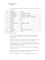
PCI Configuration Registers
This section pr
ovides a description of the PCI device configuration header
and PCI configuration registers. Any functional PCI device contains a block
of 64 double words called the PCI configuration header. The first 16 double
words are defined by the PCI specification and are known as the configura-
tion header region.
The PCI configuration header region can be in two formats known as type 0
or type 1. Header type 1 is used for PCI-to-PCI bridges. Header type 0 is
for all other devices. Figure B-1 illustrates the format of type 0 PCI device
configuration registers.
Offset
Byte3
Byte2 Byte1 Byte0
0 Device ID Vendor ID
4 Status Register Command Register
8 Class Code Revision ID
12 BIST Header Type Latency Timer Cache Line Size
16 Base Address 0
20 Base Address 1
24 Base Address 2
28 Base Address 3
32 Base Address 4
36 Base Address 5
40 Card CIS Pointer
44 Subsystem ID Subsystem Vendor ID
48 Expansion ROM Base Address
54 Reserved
56 Reserved
60 Max Latency Min Grant Interrupt Pin Interrupt Line
Figure B-1. PCI Configuration Header