biến tần delta phần 6 docx
Bạn đang xem bản rút gọn của tài liệu. Xem và tải ngay bản đầy đủ của tài liệu tại đây (299.94 KB, 20 trang )
Chapter 4 Parameters|
4-58 Revision June 2007, 0ELE, V1.00
Settings Function Description
1
Multi-Step Speed
Command 1
2
Multi-Step Speed
Command 2
3
Multi-Step Speed
Command 3
4
Multi-Step Speed
Command 4
These four inputs select the multi-speed defined by Pr.05.00 to
Pr.05.14 as shown in the diagram at the end of this table.
NOTE: Pr.05.00 to Pr.05.14 can also be used to control output
speed. There are 17 step speed frequencies (including
Master Frequency and Jog Frequency) to select for
application.
5 External Reset
The External Reset has the same function as the Reset key on
the Digital keypad. After faults such as O.H., O.C. and O.V. are
cleared this input can be used to reset the drive.
6 Accel/Decel Inhibit
When the command is active, acceleration and deceleration is
stopped and the AC motor drive maintains a constant speed.
7
Accel/Decel Time
Selection
Command
Used to select the one of 2 Accel/Decel Times (Pr.01.09 to
Pr.01.12). See explanation at the end of this table.
8
Jog Operation
Control
Parameter value 08 programs one of the Multi-function Input
Terminals MI3 ∼ MI6 (Pr.04.05~Pr.04.08) for Jog control.
NOTE: Programming for Jog operation by 08 can only be
done while the motor is stopped. (Refer to parameter
Pr.01.13~Pr.01.15)
9
External Base
Block
(Refer to Pr. 08.06)
Parameter value 09 programs a Multi-function Input Terminals for
external Base Block control.
NOTE: When a Base-Block signal is received, the AC motor
drive will block all output and the motor will free run. When
base block control is deactivated, the AC drive will start its
speed search function and synchronize with the motor
speed, and then accelerate to Master Frequency.
Chapter 4 Parameters|
Revision June 2007, 0ELE, V1.00 4-59
Settings Function Description
10
UP: Increase
Master Frequency
11
DOWN: Decrease
Master Frequency
Increase/decrease the Master Frequency each time an input is
received or continuously when the input stays active. When both
inputs are active at the same time, the Master Frequency
increase/decrease is halted. Please refer to Pr.02.07, 02.08. This
function is also called “motor potentiometer”.
12 Counter Trigger
Parameter value 12 programs one of the Multi-function Input
Terminals MI3~MI6 (Pr.04.05~Pr.04.08) to increment the AC
drive’s internal counter. When an input is received, the counter is
incremented by 1.
13 Counter Reset
When active, the counter is reset and inhibited. To enable
counting the input should be OFF. Refer to Pr.03.05 and 03.06.
14 External Fault
Parameter value 14 programs one of the Multi-function Input
Terminals MI3~MI6 (Pr.04.05~Pr.04.08) to be External Fault
(E.F.) inputs.
15
PID function
disabled
When an input ON with this setting is ON, the PID function will be
disabled.
16 Output Shutoff Stop
AC motor drive will stop output and the motor free run if one of
these settings is enabled. If the status of terminal is changed, AC
motor drive will restart from 0Hz.
17
Parameter lock
enable
When this setting is enabled, all parameters will be locked and
write parameters is disabled.
18
Operation
Command
Selection (Pr.02.01
setting/external
terminals)
ON: Operation command via Ext. Terminals
OFF: Operation command via Pr.02.01 setting
Pr.02.01 is disabled if this parameter value 18 is set. See the
explanation below this table.
19
Operation
Command
Selection (Pr 02.01
setting/Digital
Keypad)
ON: Operation command via Digital Keypad
OFF: Operation command via Pr.02.01 setting
Pr.02.01 is disabled if this parameter value 19 is set. See the
explanation below this table.
Chapter 4 Parameters|
4-60 Revision June 2007, 0ELE, V1.00
Settings Function Description
20
Operation
Command
Selection (Pr 02.01
setting/
Communication)
ON: Operation command via Communication
OFF: Operation command via Pr.02.01 setting
Pr.02.01 is disabled if this parameter value 20 is set. See the
explanation below this table.
21 Forward/Reverse
This function has top priority to set the direction for running (If
“Pr.02.04=0”)
22
Source of second
frequency
command enabled
Used to select the first/second frequency command source. Refer
to Pr.02.00 and 02.09.
ON: 2
nd
Frequency command source
OFF: 1
st
Frequency command source
04.09
Multi-function Input Contact Selection
Unit: 1
Settings 0 to 4095 Factory Setting: 0
This parameter can be used to set the status of multi-function terminals (MI1~MI6 (N.O./N.C.)
for standard AC motor drive).
The MI1~MI3 setting will be invalid when the operation command source is external terminal
(2/3wire).
12345 0
0=N.O
1=N.C
MI1
MI2
MI3
MI4
MI5
MI6
Weights
Bit
The Setting method: It needs to convert binary number (6-bit) to decimal number for input.
For example: if setting MI3, MI5, MI6 to be N.C. and MI1, MI2, MI4 to be N.O. The setting
value Pr.04.09 should be bit5X2
5
+bit4X2
4
+bit2X2
2
= 1X2
5
+1X2
4
+1X2
2
= 32+16+4=52 as shown
in the following.
Chapter 4 Parameters|
Revision June 2007, 0ELE, V1.00 4-61
01011 0
Weights
Bit
0=N.O
1=N.C
MI1
MI2
MI3
MI4
MI5
MI6
The setting value
= bit5x2 +bit4x2 +bit2x2
542
= 1x2 +1x2 +1x2
542
=32+16+4
Setting 04.09
=52
NOTE:
2 =16384 2 =8192 2 =4096 2 =2048 2 =1024
2 =512 2 =256 2 =128 2 =64 2 =32
2 =16 2 =8 2 =4 2 =2 2 =1
14 13 12 11 10
98765
4321 0
This parameter is to delay the signals on digital input terminals. 1 unit is 2 msec, 2 units are 4
msec, etc. The delay time is to debounce noisy signals that could cause the digital terminals to
malfunction.
04.26 Display the Status of Multi-function Input Terminal
Settings Read Only Factory setting: ##
Display Bit0: MI1 Status
Bit1: MI2 Status
Bit2: MI3 Status
Bit3: MI4 Status
Bit4: MI5 Status
Bit5: MI6 Status
The multi-function input terminals are falling-edge triggered. For standard AC motor drive,
there are MI1 to MI6 and Pr.04.26 will display 63 (111111) for no action.
12345 0
0=Active
1=off
MI1
MI2
MI3
MI4
MI5
MI6
Weights
Bit
04.10
Digital Terminal Input Debouncing Time
Unit: 2 msec
Settings
1 to 20
Factory Setting: 1
Chapter 4 Parameters|
4-62 Revision June 2007, 0ELE, V1.00
For Example:
If Pr.04.26 displays 52, it means MI1, MI2 and MI4 are active.
The display value 52= 32+16+4 =1 X 2
5
+ 1X 2
4
+ 1X 2
2
= bit 6 X 2
5
+ bit 5 X 2
4
+ bit 3 X 2
2
01011 0
0=Active
1=Off
MI1
MI2
MI3
MI4
MI5
MI6
Weights
Bit
This parameter is used to select the terminals to be internal terminal or external terminal. You
can activate internal terminals by Pr.04.28. A terminal cannot be both internal terminal and
external terminal at the same time.
For standard AC motor drive, the multi-function input terminals are MI1 to MI6 as shown in the
following.
12345 0
0=external terminal
1=internal terminal
MI1
MI2
MI3
MI4
MI5
MI6
Weights
Bit
The Setting method is convert binary number to decimal number for input.
For example: if setting MI3, MI5, MI6 to be internal terminals and MI1, MI2, MI4 to be external
terminals. The setting value should be bit5X2
5
+bit4X2
4
+bit2X2
2
= 1X2
5
+1X2
4
+1X2
2
=
32+16+4=52 as shown in the following.
04.27
Internal/External Multi-function Input Terminals Selection
Unit: 1
Settings
0 to 4095
Factory Setting: 0
Chapter 4 Parameters|
Revision June 2007, 0ELE, V1.00 4-63
01011 0
Weights
Bit
0=external terminal
1=internal terminal
MI1
MI2
MI3
MI4
MI5
MI6
This parameter is used to set the internal terminal action via keypad or communication.
For standard AC motor drive, the multi-function input terminals are MI1 to MI6 as shown in the
following.
12345 0
0=set internal terminal to be OFF
1= ONset internal terminal to be
MI1
MI2
MI3
MI4
MI5
MI6
Weights
Bit
For example, if setting MI3, MI5 and MI6 to be ON, Pr.04.28 should be set to
bit5X2
5
+bit4X2
4
+bit2X2
2
= 1X2
5
+1X2
4
+1X2
2
= 32+16+4=52 as shown in the following.
01011 0
Weights
Bit
0=OFF
1=ON
MI1
MI2
MI3
MI4
MI5
MI6
04.28
Internal Terminal Status
Unit: 1
Settings
0 to 4095
Factory Setting: 0
Chapter 4 Parameters|
4-64 Revision June 2007, 0ELE, V1.00
Group 5: Multi-step speeds parameters
05.00 1st Step Speed Frequency Unit: 0.01
05.01 2nd Step Speed Frequency Unit: 0.01
05.02 3rd Step Speed Frequency Unit: 0.01
05.03 4th Step Speed Frequency Unit: 0.01
05.04 5th Step Speed Frequency Unit: 0.01
05.05 6th Step Speed Frequency Unit: 0.01
05.06 7th Step Speed Frequency Unit: 0.01
05.07 8th Step Speed Frequency Unit: 0.01
05.08 9th Step Speed Frequency Unit: 0.01
05.09 10th Step Speed Frequency Unit: 0.01
05.10 11th Step Speed Frequency Unit: 0.01
05.11 12th Step Speed Frequency Unit: 0.01
05.12 13th Step Speed Frequency Unit: 0.01
05.13 14th Step Speed Frequency Unit: 0.01
05.14 15th Step Speed Frequency Unit: 0.01
Settings 0.00 to 600.0Hz Factory Setting: 0.00
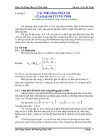
The Multi-function Input Terminals (refer to Pr.04.05 to 04.08) are used to select one of the AC
motor drive Multi-step speeds. The speeds (frequencies) are determined by Pr.05.00 to 05.14
as shown in the following.
Chapter 4 Parameters|
Revision June 2007, 0ELE, V1.00 4-65
ON ON ON ON ON ON ON ON
ONONONON
ON
ON
ON
ON
05.00
05.01
05.02
05.03
05.04
05.05
05.06
05.07
05.08
05.09
05.10
05.11
05.12
05.13
05.14
01.15
OFF
OFF
OFF
OFF
OFF
123456789101112131415
M
u
l
t
i
-
f
u
n
c
t
i
o
n
t
e
r
m
in
a
ls
0
4
.
0
5
~
0
4
.
0
8
Frequency
Master Speed
JOG Freq.
2nd speed
( 2)MI3 to MI6
1st speed
( to MI6 1)MI3
Jog Freq.
Multi-speed via External Terminals
Run/Stop
PU/external terminals
/communication
3rd speed
( 3)MI3 to MI6
4th speed
( 4)MI3 to MI6
MI6=4 MI5=3 MI4=2 MI3=1
Master frequency OFF OFF OFF OFF
1
st
speed OFF OFF OFF ON
2
nd
speed OFF OFF ON OFF
3
rd
speed OFF OFF ON ON
4
th
speed OFF ON OFF OFF
5
th
speed OFF ON OFF ON
6
th
speed OFF ON ON OFF
7
th
speed OFF ON ON ON
8
th
speed ON OFF OFF OFF
9
th
speed ON OFF OFF ON
10
th
speed ON OFF ON OFF
11
th
speed ON OFF ON ON
12
th
speed ON ON OFF OFF
13
th
speed ON ON OFF ON
14
th
speed ON ON ON OFF
15
th
speed ON ON ON ON
Chapter 4 Parameters|
4-66 Revision June 2007, 0ELE, V1.00
Group 6: Protection Parameters
06.00 Over-Voltage Stall Prevention Unit: 0.1
Settings 115V/230V series 330.0 to 410.0V Factory Setting: 390.0
460V series 660.0 to 820.0V Factory Setting: 780.0
0 Disable Over-voltage Stall Prevention (with brake unit or
brake resistor)
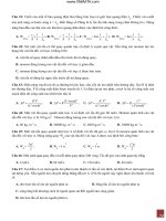
During deceleration, the DC bus voltage may exceed its Maximum Allowable Value due to
motor regeneration. When this function is enabled, the AC motor drive will not decelerate
further and keep the output frequency constant until the voltage drops below the preset value
again.
Over-Voltage Stall Prevention must be disabled (Pr.06.00=0) when a brake unit or brake
resistor is used.
NOTE
With moderate inertia load, over-voltage stall prevention will not occur and the real deceleration time
will be equal to the setting of deceleration time. The AC drive will automatically extend the
deceleration time with high inertia loads. If the deceleration time is critical for the application, a brake
resistor or brake unit should be used.
high voltage at DC side
over-voltage
detection level
output
frequency
time
Deceleration characteristic
when Over-Voltage Stall
Prevention enabled
Frequency Held
time
previous deceleration time
actual time to decelerate to stop when over-voltage
stall prevention is enabled
Chapter 4 Parameters|
Revision June 2007, 0ELE, V1.00 4-67
06.01
Over-Current Stall Prevention during Acceleration
Unit: 1
Settings 20 to 250% Factory Setting: 170
0: disable
A setting of 100% is equal to the Rated Output Current of the drive.
During acceleration, the AC drive output current may increase abruptly and exceed the value
specified by Pr.06.01 due to rapid acceleration or excessive load on the motor. When this
function is enabled, the AC drive will stop accelerating and keep the output frequency constant
until the current drops below the maximum value.
06.01
Over-Current
Detection
Level
Output
Frequency
Over-Current Stall
prevention during
Acceleration,
frequency held
output current
time
setting
frequency
previous acceleration time
actual acceleration time when over-current stall
prevention is enabled
06.02
Over-current Stall Prevention during Operation
Unit: 1
Settings 20 to 250% Factory Setting: 170
0: disable
If the output current exceeds the setting specified in Pr.06.02 when the drive is operating, the
drive will decrease its output frequency to prevent the motor stall. If the output current is lower
than the setting specified in Pr.06.02, the drive will accelerate again to catch up with the set
frequency command value.
Chapter 4 Parameters|
4-68 Revision June 2007, 0ELE, V1.00
Over-Current
Detection
Level
06.02
Output Current
Output
Frequency
Over-Current Stall
Prevention during
Operation, output
frequency decrease
over-current stall prevention during operation
06.03 Over-Torque Detection Mode (OL2)
Factory Setting: 0
Settings 0 Over-Torque detection disabled.
1 Over-Torque detection enabled during constant speed operation.
After over-torque is detected, keep running until OL1 or OL occurs.
2 Over-Torque detection enabled during constant speed operation.
After over-torque is detected, stop running.
3 Over-Torque detection enabled during acceleration. After over-
torque is detected, keep running until OL1 or OL occurs.
4 Over-Torque detection enabled during acceleration. After over-
torque is detected, stop running.
This parameter determines the operation mode of the drive after the over-torque (OL2) is
detected via the following method: if the output current exceeds the over-torque detection level
(Pr.06.04) longer than the setting of Pr.06.05 Over-Torque Detection Time, the warning
message “OL2” is displayed. If a Multi-functional Output Terminal is set to over-torque
detection (Pr.03.00=04), the output is on. Please refer to Pr.03.00 for details.
06.04 Over-Torque Detection Level (OL2) Unit: 1
Settings 10 to 200% Factory Setting: 150
This setting is proportional to the Rated Output Current of the drive.
06.05 Over-Torque Detection Time (OL2) Unit: 0.1
Settings 0.1 to 60.0 sec Factory Setting: 0.1
Chapter 4 Parameters|
Revision June 2007, 0ELE, V1.00 4-69
This parameter sets the time for how long over-torque must be detected before “OL2” is
displayed.
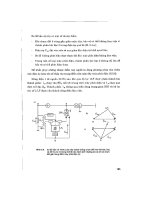
06.06 Electronic Thermal Overload Relay Selection (OL1)
Factory Setting: 2
Settings 0 Operate with a Standard Motor (self-cooled by fan)
1 Operate with a Special Motor (forced external cooling)
2 Operation disabled
This function is used to protect the motor from overloading or overheating.
40
20
60
80
100
25 50
100 150
rated frequency of the motor %
rated current of the motor%
Standard motor
(self-cooled by fan)
rated frequency of the motor %
rated current of the motor%
Special Motor
(forced external cooling)
25 50 100 150
40
20
60
80
100
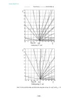
06.07 Electronic Thermal Characteristic Unit: 1
Settings 30 to 600 sec Factory Setting: 60
The parameter determines the time required for activating the I
2
t electronic thermal protection
function. The graph below shows I
2
t curves for 150% output power for 1 minute.
350
50Hz or more
10Hz
5Hz
050100150 250200
300
250
200
150
100
50
Operation
time (seconds)
Load
factor (%)
Chapter 4 Parameters|
4-70 Revision June 2007, 0ELE, V1.00
06.08 Present Fault Record
06.09 Second Most Recent Fault Record
06.10 Third Most Recent Fault Record
06.11 Fourth Most Recent Fault Record
06.12 Fifth Most Recent Fault Record
Factory Setting: 0
Readings 0 No fault
1 Over-current (oc)
2 Over-voltage (ov)
3 IGBT Overheat (oH1)
4 Reserved
5 Overload(oL)
6 Overload (oL1)
7 Motor Overload (oL2)
8 External Fault (EF)
9 Hardware protection failure (HPF)
10 Current exceeds 2 times rated current during accel.(ocA)
11 Current exceeds 2 times rated current during decel.(ocd)
12 Current exceeds 2 times rated current during steady state
operation (ocn)
13 Reserved
14 Phase-loss (PHL)
15 Reserved
16 Auto accel/decel failure (CFA)
17 Software/password protection (codE)
18 Power Board CPU WRITE Failure (cF1.0)
19 Power Board CPU READ Failure (cF2.0)
20 CC, OC Hardware protection failure (HPF1)
21 OV Hardware protection failure (HPF2)
22 GFF Hardware protection failure (HPF3)
23 OC Hardware protection failure (HPF4)
24 U-phase error (cF3.0)
25 V-phase error (cF3.1)
26 W-phase error (cF3.2)
27 DCBUS error (cF3.3)
28 IGBT Overheat (cF3.4)
Chapter 4 Parameters|
Revision June 2007, 0ELE, V1.00 4-71
29-31 Reserved
32 ACI signal error (AErr)
33 Reserved
34 Motor PTC overheat protection (PtC1)
35-40 Reserved
In Pr.06.08 to Pr.06.12 the five most recent faults that occurred, are stored. After removing the
cause of the fault, use the reset command to reset the drive.
Chapter 4 Parameters|
4-72 Revision June 2007, 0ELE, V1.00
Group 7: Motor Parameters
07.00 Motor Rated Current Unit: 1
Settings 30% FLA to 120% FLA Factory Setting: FLA
Use the following formula to calculate the percentage value entered in this parameter:
(Motor Current / AC Drive Current) x 100%
with Motor Current=Motor rated current in A on type shield
AC Drive Current=Rated current of AC drive in A (see Pr.00.01)
07.01
Motor No-load Current
Unit: 1
Settings 0% FLA to 90% FLA Factory Setting: 0.4*FLA
The rated current of the AC drive is regarded as 100%. The setting of the Motor no-load
current will affect the slip compensation.
The setting value must be less than Pr.07.00 (Motor Rated Current).
07.02 Torque Compensation Unit: 0.1
Settings 0.0 to 10.0 Factory Setting: 0.0
This parameter may be set so that the AC drive will increase its voltage output to obtain a
higher torque. Only to be used for V/f control mode.
Too high torque compensation can overheat the motor.
07.03 Slip Compensation (Used without PG) Unit: 0.01
Settings 0.00 to 10.00 Factory Setting: 0.00
While driving an asynchronous motor, increasing the load on the AC motor drive will cause an
increase in slip and decrease in speed. This parameter may be used to compensate the slip by
increasing the output frequency. When the output current of the AC motor drive is bigger than
the motor no-load current (Pr.07.01), the AC drive will adjust its output frequency according to
this parameter.
07.04
Reserved
07.05
Reserved
07.06
Reserved
07.07
Reserved
07.08
Reserved
Chapter 4 Parameters|
Revision June 2007, 0ELE, V1.00 4-73
07.09
Reserved
07.10 Accumulative Motor Operation Time (Min.) Unit: 1
Settings 0~1439 Factory Setting: 0
07.11 Accumulative Motor Operation Time (Day) Unit: 1
Settings 0 ~65535 Factory Setting: 0
Pr.07.10 and Pr.07.11 are used to record the motor operation time. They can be cleared by
setting to 0 and time is less than 1 minute is not recorded.
07.12 Motor PTC Overheat Protection Unit: 1
Factory Setting: 0
Settings 0 Disable
1 Enable
07.14 Motor PTC Overheat Protection Level Unit: 0.1
Settings 0.1~10.0V Factory Setting: 2.4
When the motor is running at low frequency for a long time, the cooling function of the motor
fan will be lower. To prevent overheating, it needs to have a Positive Temperature Coefficient
thermoistor on the motor and connect its output signal to the drive’s corresponding control
terminals.
When the source of first/second frequency command is set to AVI (02.00=1/02.09=1), it will
disable the function of motor PTC overheat protection (i.e. Pr.07.12 cannot be set to 1).
If temperature exceeds the setting level, motor will be coast to stop and
is
displayed. When the temperature decreases below the level of (Pr.07.15-Pr.07.16) and
stops blinking, you can press RESET key to clear the fault.
Pr.07.14 (overheat protection level) must exceed Pr.07.15 (overheat warning level).
The PTC uses the AVI-input and is connected via resistor-divider as shown below.
1. The voltage between +10V to ACM: lies within 10.4V~11.2V.
2. The impedance for AVI is around 47kΩ.
3. Recommended value for resistor-divider R1 is 1~20kΩ.
4. Please contact your motor dealer for the curve of temperature and resistance value for
PTC.
Chapter 4 Parameters|
4-74 Revision June 2007, 0ELE, V1.00
A
VI
A
CM
+10V
PTC
VFD-EL
47k
Ω
resistor-divider
R1
internal circuit
Refer to following calculation for protection level and warning level.
1. Protection level
Pr.07.14= V
+10
* (R
PTC1
//47K) / [R1+( R
PTC1
//47K)]
2. Warning level
Pr.07.16= V
+10
* (R
PTC2
//47K) / [R1+( R
PTC2
//47K)]
3. Definition:
V+10: voltage between +10V-ACM, Range 10.4~11.2VDC
R
PTC1
: motor PTC overheat protection level. Corresponding voltage level set in Pr.07.14,
R
PTC2
: motor PTC overheat warning level. Corresponding voltage level set in Pr.07.15,
47kΩ: is AVI input impedance, R1: resistor-divider (recommended value: 1~20kΩ)
Take the standard PTC thermistor as example: if protection level is 1330Ω, the voltage
between +10V-ACM is 10.5V and resistor-divider R1 is 4.4kΩ. Refer to following calculation
for Pr.07.14 setting.
1330//47000=(1330*47000)/(1330+47000)=1293.4
10.5*1293.4/(4400+1293.4)=2.38(V) ≒2.4(V)
Therefore, Pr.07.14 should be set to 2.4.
Chapter 4 Parameters|
Revision June 2007, 0ELE, V1.00 4-75
550
1330
temperature ( )
℃
resistor value ( )
Ω
Tr
Tr-5
℃
Tr+5
℃
07.15 Motor PTC Overheat Warning Level Unit: 0.1
Settings 0.1~10.0V Factory Setting: 1.2
07.16 Motor PTC Overheat Reset Delta Level Unit: 0.1
Settings 0.1~5.0V Factory Setting: 0.6
07.17 Treatment of the motor PTC Overheat
Factory Setting: 0
Settings 0 Warn and RAMP to stop
1 Warn and COAST to stop
2 Warn and keep running
If temperature exceeds the motor PTC overheat warning level (Pr.07.15), the drive will act
according to Pr.07.17 and display
. If the temperature decreases below the result
(Pr.07.15 minus Pr.07.16), the warning display will disappear.
07.13 Input Debouncing Time of the PTC Protection Unit: 2ms
Settings 0~9999 (is 0-19998ms) Factory Setting: 100
This parameter is to delay the signals on PTC analog input terminals. 1 unit is 2 msec, 2 units
are 4 msec, etc.
Chapter 4 Parameters|
4-76 Revision June 2007, 0ELE, V1.00
Group 8: Special Parameters
08.00 DC Braking Current Level Unit: 1
Settings 0 to 100% Factory Setting: 0
This parameter sets the level of DC Braking Current output to the motor during start-up and
stopping. When setting DC Braking Current, the Rated Current (Pr.00.01) is regarded as 100%.
It is recommended to start with a low DC Braking Current Level and then increase until proper
holding torque has been achieved.
08.01 DC Braking Time during Start-up Unit: 0.1
Settings 0.0 to 60.0 sec Factory Setting: 0.0
This parameter determines the duration of the DC Braking current after a RUN command.
When the time has elapsed, the AC motor drive will start accelerating from the Minimum
Frequency (Pr.01.05).
08.02 DC Braking Time during Stopping Unit: 0.1
Settings 0.0 to 60.0 sec Factory Setting: 0.0
This parameter determines the duration of the DC Braking current during stopping. If stopping
with DC Braking is desired, Pr.02.02 Stop Method must be set to 0 or 2 for Ramp to Stop.
08.03 Start-Point for DC Braking Unit: 0.01
Settings 0.00 to 600.0Hz Factory Setting: 0.00
This parameter determines the frequency when DC Braking will begin during deceleration.
Run/Stop
ON
OFF
01.05
08.03
Output Frequency
Minimum Output
Frequency
Start-Point for
DC Braking
Time during
Stopping
DC Braking Time
during Stopping
Chapter 4 Parameters|
Revision June 2007, 0ELE, V1.00 4-77
DC Braking during Start-up is used for loads that may move before the AC drive starts, such
as fans and pumps. Under such circumstances, DC Braking can be used to hold the load in
position before setting it in motion.
DC Braking during stopping is used to shorten the stopping time and also to hold a stopped
load in position. For high inertia loads, a brake resistor for dynamic braking may also be
needed for fast decelerations.
08.04 Momentary Power Loss Operation Selection
Factory Setting: 0
Settings 0 Operation stops (coast to stop) after momentary power loss.
1 Operation continues after momentary power loss, speed search
starts with the Master Frequency reference value.
2 Operation continues after momentary power loss, speed search
starts with the minimum frequency.
This parameter determines the operation mode when the AC motor drive restarts from a
momentary power loss.
08.05 Maximum Allowable Power Loss Time Unit: 0.1
Settings 0.1 to 5.0 sec Factory Setting: 2.0
If the duration of a power loss is less than this parameter setting, the AC motor drive will
resume operation. If it exceeds the Maximum Allowable Power Loss Time, the AC motor drive
output is then turned off (coast stop).
The selected operation after power loss in Pr.08.04 is only executed when the maximum
allowable power loss time is ≤5 seconds and the AC motor drive displays “Lu”.
But if the AC motor drive is powered off due to overload, even if the maximum allowable power
loss time is ≤5 seconds, the operation mode as set in Pr.08.04 is not executed. In that case it
starts up normally.
08.06 Base Block Speed Search
Factory Setting: 1
Settings 0 Disable
1 Speed search starts with last frequency command
2 Speed search starts with minimum output frequency (Pr.01.05)
This parameter determines the AC motor drive restart method after External Base Block is
enabled.