transformer engineering design and practice 2_phần 2 ppt
Bạn đang xem bản rút gọn của tài liệu. Xem và tải ngay bản đầy đủ của tài liệu tại đây (221.02 KB, 22 trang )
389
10
Structural Design
10.1 Importance of Structural Design
The tank of a transformer is a closed structure which is made by steel plates. It
behaves like a plate structure. Stiffeners are usually provided on all the sides and
also on the top cover of the tank to reduce stresses and deflections in plates under
various types of loads. The transformer tanks are designed for a pressure higher
than the operating one, as specified by the standards. The tank design and
fabrication are complicated due to limitations imposed by transportation (weight
and size), requirement that the oil quantity should be optimum, etc. Apart from
pressure and vacuum loads, the transformer structure has to withstand other loads
such as lifting, jacking, haulage, etc. Depending on the location of transformer
installation, the strength of the transformer structure against a seismic load may
also need to be ascertained.
Design of the transformer tank becomes complicated due to number of
accessories and fittings connected or mounted on it. These include: conservator
and radiator mounting arrangements, cooler pipes, turrets which house bushings,
support arrangement for control box housing controls for fans and pumps, support
structures for tap changer drive mechanism, valves for sampling/draining/
filtration, cable trays or conduits for auxiliary wiring, inspection covers for getting
access to important parts inside the transformer such as bushings (for making
connections) and tap changer, cable box, bus duct termination, etc. Certain
simplifying assumptions are done while analyzing the strength of the tank with all
these fittings under various loading conditions.
The stress analysis of a transformer structure can be done by mainly two
methods, viz. analytical methods and numerical methods. The analytical methods
are used for determining the stiffening requirements to limit stresses and
Copyright © 2004 by Marcel Dekker, Inc.
Chapter 10390
deflections for simple tank constructions. The tank shapes are usually complex
and the application of analytical methods is difficult. For example, if the tank is
not rectangular and if there are many pockets (extruding structures) or openings,
numerical methods such as FEM are used to determine the stresses and deflections
under various loading conditions.
10.2 Different Types of Loads and Tests
10.2.1 Loads
The transformer tank should be capable of withstanding the following loads:
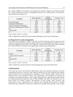
Lifting and jacking: The tank is designed to facilitate handling of the transformer.
For this purpose, lifting lugs and jacking pads (as shown in figure 10.1 (a)) are
provided on the tank. Lifting lugs, provided towards the top of the tank, are used to
lift the structure by a crane. Jacking pads provided towards the base of the tank,
are used for handling the transformer in the absence of crane, especially at the site.
Generally, four jacking pads/lifting lugs are used.
Figure 10.1 Jacking pad and lifting bollard
Copyright © 2004 by Marcel Dekker, Inc.
Structural Design 391
Lifting lugs are used for distribution transformers, where the loads are less.
Lifting bollards are used for medium and large power transformers as shown in
supporting the transformer on a floorless wagon during transport.
Haulage load: For local movements of the transformer at the place of installation,
rollers and haulage lugs are provided. The haulage lugs are provided on the lower
portion of the tank, whereas the rollers are provided under the base plate. Usually,
four rollers are provided but for large transformers six or eight rollers may be
provided. In place of rollers, a solid under-base is sometimes provided to facilitate
skidding over rails or pipes.
Seismic and wind load: The transformer has to be designed for a specified seismic
acceleration and wind load. Seismic and wind loads are very important design
considerations for bushings, supporting structures of conservator and radiators,
etc. It is very difficult, if not impossible, to conduct the seismic test on a
transformer. Seismic tests on bushings are usually specified and can be done.
Special care has to be taken for bushings because they have high cantilever load.
Transient pressure rise: When an internal fault takes place in an oil filled
transformer, a large volume of decomposed gases may get generated due to
arcing. Under these conditions, the tank structure has to withstand a rapid rise of
pressure if the pressure relief device does not act in such a short time. If the tank is
not designed with adequate factor of safety, it may rupture leading to fire hazard
and serious environmental impact due to outflow of oil. The tank should be
designed in such a way that it should be in an elastic limit under the pressure rise
conditions. The tank should not be too rigid or too flexible, otherwise it may burst.
Special devices such as sudden pressure relays are used which can act quickly
under such transient pressure rise conditions.
10.2.2 Tests
The following tests are conducted to check the strength of the transformer
structure:
Leak test: This test is meant to check whether the welded joints of the tank
structure are leak-proof or not. The test is conducted by pressurizing the tank
using air pressure. A soap solution is sprayed over all the welded joints under
specified pressure conditions. Any leak due to weld defects (crack, pin hole, etc.)
leads to bubble formation.
Vacuum test: The leak test (done with pressurized air) is followed by the vacuum
test. A specified vacuum is applied to the tank for at least an hour. The permanent
deflections measured after removal of the vacuum should be within the limits
(which depend on the size of tank) specified by the users/standards. The tank is
then cleared for shot-blasting and painting processes. This test is important
because oil filling is done under specified vacuum conditions (either at works or
Copyright © 2004 by Marcel Dekker, Inc.
figure 10.1 (b). Ride-over (transport) lugs are provided for the purpose of
Chapter 10392
site). In addition, the drying and impregnation may be done in the tank itself (e.g.,
in vapour phase drying process). The vacuum may be partial or full depending on
the voltage class and size of the transformer, and the user specifications.
Pressure test: This test is usually done after all the dielectric tests are completed in
the manufacturer’s works. The accessories like bushings are removed and a
pressure of 5 psi higher than the maximum operating pressure is generally applied
to check the pressure withstand capability of the tank. All the welded joints are
checked manually; if any oil leakage is noticed, the oil is drained and the defective
welding is rectified. The gasket leaks, if any, are also rectified.
Dye-penetration test: This test is conducted for load bearing members to detect
weld defects. In this test, the surface to be tested is cleaned thoroughly and a dye
(usually of pink colour) is applied to the weld surface. The dye is left there for
some time, typically 30 minutes, and then it is wiped clean. During this period, if
there are any weld defects in the surface being tested, the dye due to capillary
action penetrates through. After this, another solution known as developer is
sprayed on the surface. This developer brings out the dye that has penetrated
inside and leaves the pink marks on the locations where the weld defects are
present. This test is useful to detect weld integrity of load bearing members like
jacking pads and lifting lugs/bollards.
10.3 Classification of Transformer Tanks
Depending upon the position of joint between upper and lower parts of the tank,
we have two types of tank construction, viz. conventional tank and bell tank.
Conventional tank: This type of construction has a top cover as shown in
a proper placement of magnetic shunts on the tank wall for an effective stray
loss control. The disadvantage is that the core and windings are not visible at
site when the cover is removed. Hence, for inspection of core-winding
assembly, a crane with higher capacity is required to remove the core-winding
assembly from the tank.
Bell tank: In this type of tank construction, shown in figure 10.2 (b), the joint
between the two parts is at the bottom yoke level to facilitate the inspection of
core-winding assembly at site after the bell is removed. Thus, it consists of a
shallow bottom tank and a bell shaped top tank. The bell tank construction may
a height from the bottom that it comes in the path of leakage field. This may lead
For the above two types of tank, either plain or shaped tank can be used.
Copyright © 2004 by Marcel Dekker, Inc.
to a bolt overheating problem (discussed in Chapter 5).
not be convenient for a proper placement of magnetic shunts if the joint is at such
figure 10.2 (a). Since the joint is usually above the top yoke level, it facilitates
Structural Design 393
Plain tank: The plain tank of rectangular shape is quite simple in construction. It
is easy from design and manufacturing points of view since it facilitates
standardization. The design of stiffeners is also quite simple. It usually leads to
higher oil and steel quantity in high voltage transformers. If special detachable
(bolted) bushing pockets are used for center-line lead HV winding arrangement,
some saving in oil quantity can be achieved. This is usually done in large high
voltage transformers.
Shaped tank. In order to save oil quantity, tank is shaped so that its volume
reduces. The tank shaping is mainly influenced by electrical clearances (between
the high voltage leads and grounded tank), transport considerations, tap changer
mounting arrangements, etc. The lower portion of the tank may be truncated in
order to facilitate the loading of a large transformer on some specific type of
wagon (in case of rail transport) and/or to reduce the oil quantity. The tank walls
may be curved/stepped to reduce the tank size and volume. The shaped tank has
the advantage that the curved portions of its walls give a stiffening effect. But the
design of the shaped tank is more complex leading to higher engineering and
manufacturing time. Also, it may not be conducive for putting magnetic shunts or
eddy current shields on it for an effective stray loss control.
The joint between the two parts of the tank can be either bolted or welded type,
which gives the following two types of construction.
Bolted constructiom The joint between top and bottom tanks can be of bolted
type. The bolted construction, though preferred for easy serviceability, has the
disadvantage of developing leaks if gaskets deteriorate over a period of time. The
oil leakage problem can occur if there is unevenness in the plates which are bolted
or if the gaskets are over-compressed. The bolted joint may lead to overheating
hazard in large transformers.
Figure 10.2 Types of tank
Copyright © 2004 by Marcel Dekker, Inc.
Chapter 10394
Welded construction: This type of construction eliminates the possible leakage
points since the two parts of the tank are welded together. It can thus ensure leak-
proof joints throughout the life of the transformer. But if a problem or fault
develops inside the transformer, de-welding operation has to be done and there is
a limit on the number of times the de-welding and subsequent welding operations
that can be done. The C-shaped clamps are used during the welding operation and
a thin gasket is provided between the two curbs so that the welding spatters do not
enter inside the tank. Some arrangement is provided inside the tank at the top for
arresting the buckling of cover under the lifting loads.
Depending on whether the tank is totally sealed from the outside atmosphere or is
in contact with the atmosphere, the following two types of construction exist.
Breathing tank construction: Ambient temperature and load variations result in
change of oil volume. The conservator fitted on the tank top allows these volume
changes. The conservator is partially filled with oil and the space in the
conservator communicates with the atmosphere through a breather containing a
moisture absorbing material. In order to eliminate the contact of oil with the
atmosphere (to avoid moisture absorption by it), constant oil pressure system is
used in which a flexible bag (membrane) fitted inside the conservator
communicates with the outside air. The air bag contracts or expands depending on
changes in the oil volume. This construction is commonly used for large power
transformers.
Sealed tank construction In this type of arrangement, free space (filled usually
with nitrogen gas) is provided in the tank for oil expansion based on the maximum
expected oil temperature. The contact of oil with the outside atmosphere gets
totally eliminated. The tank is designed to withstand the pressure variations due to
changes in the oil volume. The construction has the disadvantage that with a
sudden fall in temperature, gases may get released from the oil seriously affecting
the dielectric strength of the insulation system. Higher clearances have to be
provided between electrodes separated by the combined oil and gas spaces (as
compared to the conventional clearances for the oil immersed electrodes).
There are some special types of tank construction based on the application and
features as given below.
Corrugated tank: This construction is used in small distribution transformers to
obviate the need of providing radiators separately. The corrugations are made by
folding a steel sheet continuously on a special purpose machine. These
corrugations are then welded to a steel frame to form a tank wall. The corrugations
provide an adequate cooling surface and also play the roll of stiffeners. In small
distribution transformers, the use of corrugated tanks is common; it can reduce the
manufacturing (fabrication) time substantially.
Copyright © 2004 by Marcel Dekker, Inc.
Structural Design 395
Cover-mounted construction: In this type of construction, core and windings are
attached to the tank cover. Lifting lugs/bollards are provided on frames. The
construction facilitates connections from the windings to cover mounted
accessories like in-tank type OLTC and small bushings. Access to the lifting lugs/
bollards is provided through the inspection openings on the cover. The complete
core-winding assembly with the top cover can be lifted by means of lifting lugs/
bollards and lowered into the tank. The whole arrangement can be made compact
and simpler. For servicing purpose, the un-tanking of the core-winding assembly
is possible without removing the bushing connections.
Perforated tank: This type of tank is used in dry-type transformers, where the
tank is used just as an enclosure to house the active parts. The perforations allow
the flow of air cooling the inside active parts. The construction generally consists
of detachable panels which cannot take any lifting load. The absence of oil and the
presence of perforations usually lead to higher noise level in dry transformers as
compared to oil cooled transformers, and special measures need to be taken to
reduce the noise level.
10.4 Tank Design
The mechanical design is taken up after the electrical design of a transformer is
finalized. The mechanical design requires following inputs: core dimensions
(diameter, center-to-center distance, etc.), winding details, design insulation
details of accessories (bushings, radiators, fans, pumps, protection devices, etc.),
weight and size limitations during transport and at site, etc. The designer has to
keep in mind the requirements of tank shielding arrangements. The tank
dimensions and profile are decided in a layout drawing drawn to scale considering
electrical clearances, magnetic clearances, transport size limits and
manufacturability. The design of stiffeners is a very important aspect of tank
design. An effective stiffening arrangement can reduce the tank plate thickness.
The stiffeners are designed in such a way that the tank weight is minimum, and at
the same time it should be able to withstand the specified loads. The stiffeners
Flat stiffeners: These are used in small rating transformers. These stiffeners,
which have low section modulus, are suitable for small tanks. They are more
compact as compared to the other types of stiffeners.
T stiffeners: These stiffeners offer higher section modulus as compared to the flat
stiffeners but lower than the box stiffeners (for the same cross-sectional area).
They occupy more space than the flat stiffeners but less than the box stiffeners.
They are useful in the cover area where less space is available due accessories like
bushings, turrets, etc. because of which the box stiffeners cannot be used. These
Copyright © 2004 by Marcel Dekker, Inc.
levels at various electrodes (as described in Chapter 8), details of tap changer,
used are of following types (shown in figure 10.3):
Chapter 10396
are also useful for stiffening a dome shaped cover/irregular cover where stiffening
is difficult with the other types of stiffeners.
Box stiffeners: For large power transformers, the flat and T type stiffeners are not
suitable because their number increases. The box stiffeners give much higher
value of section modulus, and hence they are used in large power transformers.
Aesthetically they look better than the other types of stiffeners. The box stiffeners
can also be used for other purposes. A lifting bollard can be embedded into a box
stiffener for the lifting purpose. A jacking arrangement can be achieved if a plate is
provided (with gussets) at the bottom of a box stiffener. It can also be used to
provide an extra gas space in sealed transformers.
Usually, the stiffening is done vertically. Sometimes horizontal stiffeners are also
provided. The stiffeners are designed to distribute the lifting load properly (more
uniformly). The location of stiffeners on the tank may be affected by space
restrictions. The stiffener dimensions and location depend not only on the strength
considerations but also on the various fittings and accessories which have to be
mounted on the tank.
Figure 10.3 Types of stiffeners
Copyright © 2004 by Marcel Dekker, Inc.
Structural Design 397
The stiffeners can be designed as simply supported or fixed support structures.
In the simply supported case, the stiffeners are terminated at some distance from
the top or bottom edge of the tank plates, which may result in higher deflection. If
the stiffener ends are anchored to the top curb and bottom plate (in a conventional
tank) then it is termed as the fixed support stiffener, and this arrangement gives
lower deflection. The T stiffeners and flat stiffeners can be terminated on the curb
whereas box stiffeners can not be terminated because of the space requirement for
bolting operations. For practical reasons one has to leave some space between the
termination of a box stiffener and curb. In such cases, the box stiffener can be tied
to the curb by means of a gusset.
Since many accessories are mounted on the top cover, an adequate space may
not be available for its stiffening. In such cases, higher cover plate thickness needs
to be used with the application of flat or T stiffeners wherever possible.
The base plate of a tank is usually much thicker than its vertical plates. It is
designed to carry a total load corresponding to the sum of entire core-winding
assembly weight, oil head and test pressure. The base plate can be stiffened by
cross channels to reduce its thickness. The box stiffeners may also be used
sometimes for stiffening of the base plate.
A number of local small stiffeners are provided under extended projections/
pockets and shaped tank parts.
10.5 Methods of Analysis
The design of transformer tank structure comprises mainly the analysis of the
combined behavior of plates and stiffeners.
10.5.1 Analytical method
In an analytical method, which can be applied to plain rectangular tanks, each side
(plate) of tank is divided into number of plate panels. One side of a rectangular
tank with three vertical stiffeners is shown in figure 10.4. The center line of a
stiffener is taken as the panel boundary. Hence, for the purpose of analysis there
are four panels. These panels are subjected to loads such as pressure, vacuum, etc.
as described earlier.
Figure 10.4 One side of a rectangular tank
Copyright © 2004 by Marcel Dekker, Inc.
Chapter 10398
The stress analysis of each panel can be done by using theory of plates. The
stress calculation for simply supported and fixed type of rectangular plates is an
integral part of the transformer tank design. Let us first analyze a simply supported
plate.
Consider a rectangular plate of dimensions a×b and thickness t as shown in
figure 10.5. Let the load per unit area be w; hence the total load on the plate is wba.
The load on the plate area on one side of the diagonal is (1/2) wba, which is
denoted by W. This load acts on the centroid of the triangular area DEF. The
centroid is at a distance of (1/3) h from DF.
Experiments on the simply supported rectangular plate show that the plate has
a tendency to curl up at the corners, and the resultant pressure on each edge acts at
its mid-point. The diagonal DF is the most critical section when one side of the
plate is not very much longer than the other side [1]. The moment arm for the two
reactions R
1
and R
2
is same. From the conditions of symmetry and equilibrium,
their sum is equal to (1/2) wba.
The bending moment about DF is
(10.1)
Substituting the expressions for reactions and load we get
(10.2)
Figure 10.5 Rectangular simply supported plate under uniform load
Copyright © 2004 by Marcel Dekker, Inc.
Structural Design 399
The length of DF is Therefore, the average bending moment per unit
length of the diagonal is
(10.3)
From the similarity of triangles FGE and FED we have
(10.4)
Substituting the expression of h in equation 10.3 we get
(10.5)
The section modulus (z) of the plate per unit length along the diagonal is equal to
(1/6) t
2
. Accordingly, the bending stress at the surface of the plate across the
diagonal DF in the simply supported case is
(10.6)
The analysis for a plate with fixed edges is quite involved. The deflection for a
fixed plate is symmetrical and maximum at its centre. The ratio of two adjacent
sides play an important role in deciding the deflection, and the bending moment at
bending moment divided by the section modulus gives the maximum bending
can be approximately considered as fixed and the fourth (top) side can be
considered as simply supported. The analysis for this case is given in [2].
In order to simplify the calculations, it can be assumed that the behavior of the
tank plate is in between the simply supported and fixed edge conditions. The
stresses calculated under these two conditions are multiplied by empirical factors
to calculate the resultant stress (
σ
r
),
σ
r
=k
1
σ
ss
+k
2
σ
fe
(10.7)
where
σ
ss
and
σ
fe
are stresses for simple supported and fixed edge conditions
respectively. The constants k
1
and k
2
are empirical factors such that k
1
+k
2
=1.0.
Copyright © 2004 by Marcel Dekker, Inc.
stress in the plate. For the panels of a tank side as shown in figure 10.4, three sides
various locations is calculated by using analytical methods [2]. The maximum
Chapter 10400
The numerical methods give accurate stress and deflection values without
having to do simplifying assumptions as done in the analytical methods.
10.5.2 Numerical method
The analytical solution is quite acccurate and is a mathematical expression
that gives the value of a desired unknown quantity at any location in a body.
The analytical methods can be used for simplified situations. For problems
involving complex geometries, material properties and boundary conditions,
the designer depends on numerical methods which give sufficiently accurate
solutions.
The finite element method (FEM) is a very effective numerical analysis tool for
the simulation of structural components under various loading conditions. The
FEM analysis can be used for material optimization, reliability enhancement,
failure analysis and corrective action, verification of new designs, etc. Before the
advent of FEM, many approximations had to be made in the analytical methods
for complex tank geometries, and it was almost impossible to predict the exact
performance of the structures under the given loading conditions. It was not
possible for the designer to know the margin or factor of safety for new designs.
Due to this ignorance factor, the designer had to put extra material thereby
increasing the transformer cost. Using FEM analysis, it is possible to detect high
stress zones and take suitable corrective/preventive actions. The FEM analysis can
be used to investigate problems like vibrations, buckling, non-linear behaviour,
etc.
The steps of FEM analysis have been given in Section 3.4 (while discussing
reactance calculation). A given problem domain is divided into a number of
elements, that are straight lines for 1-D domains, triangular or quadrilateral
elements for 2-D domains, and tetrahedral or cubical elements for 3-D domains.
The transformer tanks can be considered as 2-D shells and can be discretized into
2-D shell elements. The required solution function is approximated over an
element by interpolation between the values at its nodes. The interpolating
functions may be linear or higher order polynomials. Let u
i
and v
i
be the x and y
components of displacements at the nodes of a triangular element respectively
(i=1, 2, 3). The vector U=(u
1
v
1
u
2
v
2
u
3
v
3
)
T
then represents nodal displacements.
The displacements over the entire element area maybe given as [3]
(10.8)
where N
i
(x, y) are the interpolating functions. Using standard symbols [3], the
strain vector
ε
=(
ε
x
ε
y
γ
xy
)
T
is related to the displacements as
Copyright © 2004 by Marcel Dekker, Inc.
Structural Design 401
or
ε
=[B]U (10.9)
The potential energy of the element (e) is dependent on the displacements over
the element area. As per equation 10.8, it becomes a function of the nodal
displacement vector U. In the absence of internal (body) forces, initial strains and
initial stresses, it is given by
(10.10)
where D is an elasticity matrix containing the appropriate material properties, F is
the nodal load vector, and V is the element volume. Minimizing the above
expression gives the governing equation which determines the solution, i.e.,
∂E/∂U=[K]
(e)
U-F=0 (10.11)
where This forms the element equation.
All such element equations are combined by first replacing the element-wise
nodal quantities by the corresponding global nodal quantities, and adding all the
element equations. This forms the global system of linear equations,
(10.12)
where U and F are the global displacement and load vectors, and K is the global
stiffness matrix. The above linear system of equations is a large and sparse system
of equations, solved normally by the iterative methods especially suited for
solving such systems. The solutions can be refined for obtaining more accurate
solutions by either using a finer mesh with smaller elements or using higher order
interpolating functions over the elements or both.
10.6 Overpressure Phenomenon in Transformers
The problem of explosions of oil insulated equipment as a result of low-
impedance internal faults has been a major concern. When an internal fault takes
place inside an oil filled transformer, arcing produces a large amount of
Copyright © 2004 by Marcel Dekker, Inc.
Chapter 10402
decomposed gas increasing the tank pressure rapidly. The pressure relief device
may not be able to keep up with the gas generation rate and the tank can rupture
[4]. The severity of an internal fault depends mainly on the arc energy and the tank
expansion coefficient. The higher the arc energy and the lower the tank expansion
coefficient, the higher the severity is. The arc voltage is not related very much to
the arc current and is mainly a function of arc length, electrode shape, pressure,
etc. [5,6]. Since the oil is relatively incompressible and since the bottom plate and
side plates of the tank act together as a rigid structure, the tank cover is usually
subjected to the overpressures [7]. In order to reduce such consequences, it is
necessary to determine the resulting overpressures for different faults and
geometrical parameters of the transformer.
Use of flange reinforcing measures such as C-shaped clamps and joint
reinforcement beams [5] is made to increase the strength of tank structures against
excessive overpressures. In a 3-phase split type transformer the major part of the
tank is divided into three parts (one part per phase), with a common ducting for
connections, to take care of transport limits. The pressure rise in such a
configuration may reach an excessive level due to a small expansion coefficient
and the effect of kinetic energy of the oil. Use of a diaphragm type conservator as
a pressure reducing space is suggested as a countermeasure.
The phenomenon has been studied both analytically and experimentally.
Different formulations are proposed for predicting the overpressures during a low
impedance fault. In [8], the results of analysis and experimental work are
combined to get a semi-empirical equation for the peak pressure in the air space of
a pole-type distribution transformer. It is reported that the arc length and (i
2
t)
arc
are
the most significant variables, former being generally beyond control. However,
this semi-empirical equation is probably only valid for geometrically similar
transformers and hence may not be generalized. A comprehensive explanation of
the different failure modes of distribution transformers is given in [9], The
overpressure phenomenon is studied using high speed photography and it is
shown experimentally that the arc depth under oil plays an important role in the oil
motion, compression of the air space and the resulting overpressure. It is also
reported that the maximum pressure exerted against the transformer tank cover
depends on two principal parameters: one is the arc energy expended per unit
volume of the air space, and another is the efficiency of the process by which the
arc energy is converted into the kinetic energy.
The equations for the static pressure within the faulted oil filled distribution
transformer as a result of arcing and gas generation are given in [4]. The equations
are derived under known conditions such as tank dimensions, air space, specific
fuses and specific pressure relief devices, and unknown quantities such as fault
current, arc length, arc location and gas temperatures. The finite difference
approach is proposed in [10] to study the phenomenon of arcing in oil insulated
equipment. The solution of proposed method is compared with that of an
analytical formulation for infinite cylinder filled with oil. The application of the
Copyright © 2004 by Marcel Dekker, Inc.
Structural Design 403
finite difference method for analysis of low-impedance faults in a cylindrical
pole-type distribution transformer is given in [11].
10.7 Seismic Analysis
Earth quake is a dynamic phenomenon which occurs due to release of energy
below the ground because of instability of the earth’s internal structure. The
source of earthquake is a sudden displacement of ground on both sides of a fault
which results from a rupture of a crystal rock. The size of earthquake is measured
by the amount of strain energy released at the source. The earthquake produces
random ground motions which are characterized by simultaneous but statistically
independent horizontal and vertical components. A moderate earthquake may
persist for 15 sec to 30 sec and a severe one for 60 sec to 120 sec. The vibration of
ground motion may be magnified many fold in the equipment. The magnification
depends on the characteristic frequency of vibration of the system consisting of
soil, foundation and equipment.
Transformers are important elements of power supply systems. It is very
essential that utmost care is taken while designing their tank and accessories for
seismic withstand. If they are not adequately designed, it could result into
anchorage failure, bushing failure, conservator bracket deformation, oil leakage
and other miscellaneous damages. Certain accessories and protection devices
(e.g., buchholz relay) may malfunction during an earthquake giving a false
indication of fault in the transformer. The main principle for improving strength
under earthquake conditions is that the natural frequency of the transformer and
its parts should be above 30 Hz ensuring a lower acceleration factor.
Design for seismic conditions is based on the seismic zone where the
equipment would be installed. The transformer user should provide information to
the transformer manufacturer about the seismic activity in terms of maximum
accelerations, response spectra or time histories. The seismic zone of a place
defines the intensity of an earthquake which is likely to hit that place. As per IEEE
C57.114–1990 (IEEE seismic guide for power transformers and reactors), typical
values of maximum ground acceleration range from 0.1 g (zone 1) to 0.5 g (zone
4), where g is the acceleration due to gravity. If the transformer is not ground
mounted, the acceleration at the mounting location has to be considered.
Although seismic withstand can be most accurately checked by a laboratory
test on an equipment, it is very difficult to conduct the test on a product like
transformer. Hence, the following three calculation methods are commonly used
for checking the seismic withstand of transformers.
Seismic coefficient method: This is an approximate method in which normal
static stress calculations are done with certain seismic accelerations applied to the
center of gravity of structures. Seismic coefficients are applied separately to
various vulnerable components such as bushings, conservators, radiators, etc.,
Copyright © 2004 by Marcel Dekker, Inc.
Chapter 10404
which are mostly the overhanging or extended portions of the transformer
structure. This method does not take into consideration the natural frequencies of
the structure or its components.
Response spectrum method: As per IEEE C57.114–1990, when the natural
frequencies of a transformer are lower than about 30 Hz, the static method should
not be used and one has to take into account the natural frequencies of the
structure. The response spectrum method determines the dynamic response which
depends on the natural frequencies of the structure. The transformer needs to be
analyzed as a spring-mass model using response spectrum curve with an
appropriate damping factor. The response of the structure to an earthquake due to
each mode of vibration is calculated, and the total response is determined by
combining the individual modal responses (square root of sum of squares
technique). A numerical method like FEM needs to be used for this purpose. The
FEM analysis gives stresses, accelerations and displacement plots which help in
identifying weak structures that need to be strengthened.
Time history method: This method is computationally very intensive and requires
actual earthquake data. This method can be used for analysis of structures which
underwent an earthquake whose time history is known.
Since it is not possible to test the seismic withstand of transformers by an actual
test, experimental investigations have been done to evaluate their natural
frequencies and mode shapes of vibrations. The results of multi-point random
excitation test and forced vibration test are compared with that of FEM analysis in
[12]. A significant global deformation mode is reported at a frequency of about 3.5
Hz. The results of experimental tests on a buchholz relay are compared with that
of the numerical analysis. In another reference [13], the efficacy of amplification
factor and response factor of a bushing given in IEC standard (IEC 61463, Ed. 1.1,
Bushings—Seismic qualification) is examined.
The design precautions suggested by IEEE C57.114–1990 are: placing of
transformer and interconnected accessories/equipment on a strong and common
foundation to reduce a differential movement during an earthquake, firm
anchoring of the transformer by welding its base to the structural steel members
embedded in or firmly fixed to the concrete foundation, etc.
10.8 Transformer Noise: Characteristics and Reduction
With the growing consciousness on the ill effects of noise pollution, many users
are specifying lower noise levels for transformers. While the trend of ever
increasing transformer ratings implies a corresponding rise in noise level, noise-
reducing measures have to be adopted to make the transformer quieter. By using
modern design methods and materials, noise emissions from the transformer can
be economically lowered to the acceptable levels. In order to reduce noise level, it
is very important to know and understand the sources of noise. The noise pressure
Copyright © 2004 by Marcel Dekker, Inc.
Structural Design 405
generated by vibration of core and windings is transmitted to tank surfaces though
the oil medium. Since the oil is relatively incompressible, the noise is transmitted
without appreciable damping. The tank responds to these noise waves depending
on its natural frequencies and mode shapes of vibrations.
The principal source of transformer noise, the magnetic core, has been
controlled noise and equipment noise are discussed.
10.8.1 Load-controlled noise
This noise is emitted by a loaded transformer in addition to its no-load noise. It is
caused by electromagnetic forces between the windings resulting from the
leakage fields and is proportional to the square of the load current. These forces
cause the winding vibrations and acoustic radiations having frequency of 100 or
120 Hz (twice the power frequency). It is mainly the axial vibrations of the
winding which contribute to the noise (the radial vibrations can be significant only
for winding diameters greater than 6 meters [14]). The contribution of load-
controlled noise to the overall noise level of the transformer becomes significant
when the operating flux density in the core is lower than 1.4 T. At such a low value
of flux density, noise from the core is considerably reduced. The other sources of
load-controlled noise are the vibrations of tank walls and the magnetic shunts
placed on them. If the magnetic shunts are rigidly anchored to the tank wall, the
noise due to their vibrations is usually low.
The vibration amplitudes produced by a given axial compressive force
(corresponding to a load current flowing in a winding) depend on the winding
properties, viz. mass, modulus of elasticity and damping. Pressboard and other
insulating materials play an important role in deciding the winding response. The
winding noise can be kept as low as possible by using a pressboard material with
a high damping coefficient and applying a proper value of pre-stress to the
winding. The winding natural frequencies should be quite away from the
frequencies of the exciting eompressive forces (twice the power frequency and its
multiples), since a resonance will amplify the vibrations and noise.
The loaded transformer represents a typical magneto-mechanical system
immersed in a fluid (oil). For developing the numerical method for accurate
calculation of the load-controlled noise, the electromagnetic field, mechanical
displacement field, acoustic pressure field and their couplings have to be
considered as one system. Due to the complexity of this multi-field problem, a
combination of the finite element and boundary element methods is used in [15]
for the prediction of the load-controlled noise of power transformers.
10.8.2 Noise due to cooling equipment
Fan noise is a result of vortex flows in the vicinity of its blades. The noise is a
function of air delivery, blade size and speed. While the noise due to core produces
frequencies in the range of 100 to 600 Hz, the frequencies associated with the
Copyright © 2004 by Marcel Dekker, Inc.
elaborated in Chapter 2. In this chapter the other two sources of noise, viz. load-
Chapter 10406
noise due to cooling equipment (fans and pumps) are usually below and above
this frequency range in the sound spectrum. In general, high flow speed of cooling
medium of fans and pumps should be avoided.
Since the fan noise is a function of its speed and circumferential velocity, a low
speed fan has a smaller noise level. As the speed is lowered, air delivery also
reduces necessitating an increase in number of fans. Many times, the noise level
specified is so low that it may not be possible to get such a low noise fan.
Therefore, ONAN (OA) cooling should be specified/used in place of mixed
ONAN/ONAF (FA) cooling for small and medium rating power transformers,
even if it results in increase of number of radiators.
A radiator noise is caused by the tank vibration transmitted through cooler
pipes connecting the tank and radiator (structure borne vibration). Pipe-work and
supporting structures should be designed such that there is no resonance.
10.8.3 Noise level reduction
operating peak flux density in the core is reduced. A lower value of the operating
flux density also results in higher material cost and size of the transformer. Hence,
other cost-effective noise reduction methods are commonly used which are now
described.
There are different ways by which the noise can be reduced. Methods like
stiffening the bracing or supporting parts and adding cushions between parts of a
transformer have long been known and used [16] for reducing vibrations and
noise. Barrier walls and total sound-proof enclosures have also been commonly
used [17]. An easy but expensive way would be to put the transformer in a closed
room whose walls and floor are massive. The noise reduces as it tries to pass
through a massive wall. The noise can also be reduced by building a free-standing
enclosure of concrete and steel plates around the transformer. However, this
method has some disadvantages (e.g., a large area is needed for the transformer
installation). Use of sound insulation panels is another way of getting reduced
noise levels without any additional space requirement. The closely fitting sound
insulation panels described in [18] are mounted between reinforcing channels
(stiffeners). The assembly consists of a resilient steel sheet, a steel plate and
weights. The steel sheet connects the steel plate to the stiffeners. The weights are
placed at the boundaries of the plate and sheet to avoid the transmission of
structure borne vibrations from the stiffeners to the steel plate. The noise level
reduction of 14 dB is reported by the use of these insulation panels. Development
of a vibration controlled sound insulation panel, capable of reducing the noise
generated from a transformer by 12 to 13 dB, is reported in [19]. The panel
consists of highly damped plates which are mounted on the side walls of the
transformer tank with isolation rubber pieces.
A substantial reduction of noise (of the order of 15 dB) can also be obtained by
using a double tank design. The transformer is contained in the inner tank which is
Copyright © 2004 by Marcel Dekker, Inc.
It is pointed out in Chapter 2 that a reduction in noise level is not significant if the
Structural Design 407
supported inside the outer tank. Both the tanks are suitably insulated from each
other to reduce the structure borne sound. Glass wool is placed in the space
between the two tanks for the effective noise reduction.
Active noise control is one more technique for the noise level reduction, in
which an anti-phase noise is generated and superimposed on the noise emitted by
the transformer. It requires very sophisticated instrumentation and computational
facilities. The active control scheme implemented with Digital Signal Processing
(DSP) is reported in [20]. It is reported that a noise level reduction of 5 to 15 dB
can be achieved depending upon the effectiveness of implementation of the
technique.
In dry type distribution transformers (resin impregnated or cast resin), due to
the absence of oil and presence of openings/perforations on the tank (for effective
air circulation and cooling), the noise level can be higher. Hence, the core limbs
can be of bolted construction in addition to the bolted yokes to give more rigidity
to the core structure and reduce the noise emanating from it.
The noise reduction techniques can be summarized as below.
1. Reduction in core flux density: This gives noise reduction of 3 to 5 dB for a
reduction in flux density by 10% (or approximately 2 dB per flux density
reduction of 0.1 T). The method has adverse effects on the cost and size of
transformers.
2. Hi-B grade and scribed core materials give 2 to 3 dB reduction as compared to
non Hi-B grades.
3. Avoidance of core resonance by calculation of core resonant frequencies: The
core natural frequencies should not coincide with the excitation frequencies
4. Increased core damping: By application of suitable viscoelastic or adhesive
coating to the core laminations, the noise level can be reduced.
5. It should be ensured that any links or attachments to the core are flexible so
that they do not transmit the vibrations.
6. Use of step-lap joint: It gives reduction by about 4 to 5 dB as compared to the
mitred construction for the commonly used flux densities (1.6 to 1.7 T).
7. The corner protrusions of the built core should be cut since they may
contribute to noise due to vibrations (also they are not useful as they do not
generally carry any flux).
8. The clamping pressure on the core should be adequately distributed so that no
appreciable length of the core is left unclamped. If limbs/yokes are clamped
with resin-glass or fiber-glass tapes, the pitch (distance between two tapes)
should be small so that an adequate uniform pressure is applied.
9. To reduce the structure borne vibrations, the core-winding assembly should
be isolated from the tank base by use of oil compatible anti-vibration pads
between them. Use of anti-vibration pads is also made between frames and
tank. Such isolations can give a noise level reduction of 2 to 4 dB.
Copyright © 2004 by Marcel Dekker, Inc.
as discussed in Chapter 2.
Chapter 10408
10. Use of sound insulation panels between tank stiffeners can give 5 to 15 dB
reduction.
11. An increased tank wall mass, by use of sand in hollow braces on the wall, can
give appreciable noise level reduction.
12. Use of double tank design: Inner and outer tanks are suitably insulated from
each other to eliminate structure borne vibrations. Also, suitable sound
absorbent wool is placed between the two tanks. The noise reduction is about
15 dB.
13. Complete concrete or brick wall enclosures: The noise reduction is about 20
to 30 dB, but the method is quite expensive.
14. Use of active phase cancellation technique: The sound emitted by a
transformer is overlaid by externally applied anti-phase sound. A noise level
reduction of 5 to 15 dB may be possible.
15. If the transformer noise level required is too low to get a fan with a lower
noise level, ONAN (OA) cooling may be specified/used in place of mixed
ONAN/ONAF (FA) cooling for small and medium rating transformers.
Some precautions which need to be taken at the site for noise level control are:
16. The reflecting surfaces should not coincide with half the wavelength of
frequencies of noise emitted by the transformer [21] (to avoid standing waves
and reverberations/echoes).
17. Fire walls are sometimes placed adjacent to the transformer. It may not be
possible to place them at a location so that no undesirable reflections occur. In
such cases a sound-absorbent material, suitable for outdoor use, may have to
be applied on the walls.
18. Dry type distribution transformers are mostly located in a room inside a
building. With the walls of the room having a low sound absorption
coefficient, the sound emitted by the transformer reflects back and forth
between the walls. This may lead to a considerable increase of noise level.
These aspects should be duly considered by the users (while designing the
room) and manufacturers (while designing the transformer).
19. If simple barrier walls are used for obstructing the noise, they are not effective
at the edges. The walls have to be extended at right angles on one or both ends
with an application of sound-absorbent material for better results.
20. The transformer should not be mounted on a foundation on which adjacent
walls are also mounted because the vibrations from the transformer may get
transmitted through the foundation to the walls. The vibration of these walls
will increase the overall noise level.
21. A solid connection between a vibrating transformer and any solid structure in
the vicinity should be avoided (flexible connections can be used as far as
possible).
22. The tank base can be isolated from the supporting ground/foundation by a
suitable vibration-damper to reduce structure borne vibrations.
Copyright © 2004 by Marcel Dekker, Inc.
Structural Design 409
10.8.4 Noise level measurement
A noise level is commonly measured in decibels (dB) by comparing the pressure
generated by a noise source with some standard level. The noise level is measured
basically two methods of noise measurement: sound pressure measurement and
sound intensity measurement. The details of test methods and acceptable test
environment conditions are given in IEC standard 60076–10 (Determination of
sound levels, First Edition, 2001). Sound pressure level is a scalar quantity and
requires simple instrumentation.
Sound intensity is a vector quantity and the method measures directional
sound. It is therefore less affected by a background noise. Hence, the sound
intensity method can give more accurate measurements in the presence of
background noise. However, sound intensity measurements require higher skill
and more sophisticated instrumentation. Information about the location and
characteristics of noise sources can be obtained by studying the frequency
spectrum.
Apart from design challenges, the measurement of low noise poses a difficult
problem. The minimum level of noise which can be measured is limited by the
ambient noise conditions in the test area. Special enclosures may have to be used
to shield the instruments (test set-up) and transformer from the high ambient
noise.
References
1. Seely, F.B. and Smith, J.O. Advanced mechanics of materials, John Wiley and
Sons, New York, London, 1952.
2. Timoshenko, S. and Woinowsky-Krieger, S. Theory of plates and shells,
McGraw-Hill Inc., Singapore, 1959.
3. Zienkiewicz, O.C. Finite element method, McGraw Hill, London, 1977.
4. Goodman, E.A. and Zupon, L. Static pressures developed in distribution
transformers due to internal arcing under oil, IEEE Transactions on Power
Apparatus and Systems, Vol. PAS-95, No. 5, September/October 1976, pp.
1689–1698.
5. Kawamura, T., Ueda, M., Ando, K., Maeda, T., Abiru, Y., Watanabe, M., and
Moritsu, K., Prevention of tank rupture due to internal fault of oil-filled
transformer, CIGRE 1988, Paper No. 12–02.
6. Tagaki, T., Ishii, T., Okada, T., Kurita, K., Tamura, R., and Murata, H. Reliability
improvement of 500 kV large capacity power transformer, CIGRE 1978, Paper
No. 12–02.
7. Hamel, A., Dastous, J.B., and Foata, M. Estimating overpressures in pole-
type distribution transformers—Part I: Tank withstand evaluation, IEEE
Transactions on Power Delivery, Vol. 18, No. 1, January 2003, pp. 13–119.
8. Mahieu, W.R. Prevention of high-fault rupture of pole-type distribution
Copyright © 2004 by Marcel Dekker, Inc.
on ‘A’ weighted scale which closely follows the sensitivity of human ear. There are
Chapter 10410
transformers, IEEE Transactions on Power Apparatus and Systems, Vol. PAS-
94, No. 5, September/October 1975, pp. 1698–1707.
9. Barkan, P., Damsky, B.L., Ettlinger, L.F., and Kotski, E.J. Overpressure
phenomena in distribution transformers with low impedance faults: experiment
and theory, IEEE Transactions on Power Apparatus and Systems, Vol. PAS-
95, No. 1, January/February 1976, pp. 37–47.
10. Foata, M., Iordanescu, M., and Hardy, C. Computational methods for the
analysis of explosions in oil-insulated equipment, IEEE Transactions on Power
Systems, Vol. 3, No. 1, February 1988, pp. 286–293.
11. Dastous, J.B., Foata, M., and Hamel, A. Estimating overpressures in pole-
type distribution transformers—Part II: Prediction tools, IEEE Transactions
on Power Delivery, Vol. 18, No. 1, January 2003, pp. 120–127.
12. Bellorini, S., Bettinali, F., Salvetti, M., Gatti, F., Zafferani, G., and Monzani,
O. Mechnical Seismic behavior of power transformers, CIGRE 1998, Paper
No. 12–212.
13. Bellorini, S., Bettinali, F., Salvetti, M., and Zafferani, G. Seismic qualification
of transformer high voltage bushings, IEEE Transactions on Power Delivery,
Vol. 13, No. 4, October 1998, pp. 1208–1213.
14. Reiplinger, E. Study of noise emitted by power transformers based on today’s
viewpoint, CIGRE 1988, Paper No. 12–08.
15. Rausch, M., Kaltenbacher, M., Landes, H., Lerch, R., Anger, J., Gerth, J., and
Boss, P. Combination of finite and boundary element methods in investigation
and prediction of load-controlled noise of power transformers, Journal of Sound
and Vibration, 250 (2), 2002, pp. 323–338.
16. George, R.B. Power transformer noise: Its characteristics and reduction, AIEE
Transactions, March 1931, pp. 347–353.
17. Murray, C.S. Transformer audio noise problems on an electric power system,
AIEE Transactions, Vol. 68, 1949, pp. 740–752.
18. Kanoi, M., Hori, Y., Maejima, M., and Obta, T. Transformer noise reduction
with new sound insulation panel, IEEE Transactions on Power Apparatus
and Systems, Vol. PAS-102, No. 9, September 1983, pp. 2817–2825.
19. Ebisawa, Y., Hirai, K., Suda, K, and Ikeda, M. Development of new type sound
insulation panel for transformers, International Conference on Transformers,
Transformer-97, Kolobrzeg, May 1997, pp. 37–42.
20. Teoh, C., Soh, K., Zhou, R., Tien, D., and Chan, V. Active noise control of
transformer noise, International Conference on Energy Management and
Power Delivery, EMPD ‘98. Vol. 2, March 1998, pp. 747 -753.
.federalpacific.com/: Understanding transformer noise.
Copyright © 2004 by Marcel Dekker, Inc.
21. http://www