FLAME SAFEGUARn CONTRULS phần 5 ppsx
Bạn đang xem bản rút gọn của tài liệu. Xem và tải ngay bản đầy đủ của tài liệu tại đây (1.27 MB, 36 trang )
TIMER
CAMS
CAN
BE
ADDED
(FIG.
36)
Extra
~ce
on
lh9
programmer
chassis allowS
cams
to
be
added
10
lh9
timet wifhout redeslgt ThI6
may
be
nec-
essary
If
more
timer
contacts
are nq.J1red to mEleI future
COdes.
ALL
IlELAVS
A,RE
VISIBLE.
LA,BELEo. A,NO.ACCESSIBLE
'.0
FIG.36-ADDITIONAL
FEATURES
OF
THE
R4140.
TIMER
SWITCH
(FIG.
37)
A
limer
switch lets
the
c:perator
stop
the
Iimer
near the
end
of
prepurge
or
during
the
PUo!
Flame-Establishing
P&-
ried
10
facilitate checkoUl
and
troubleshooting. The
switch
win
nol
slop
the
Iimer
when
the
main fuel
val~e/S)
is
energized.
S9111NG
CLI9
HOLDS A,MPLIFIER
'"
-~-:
. • IlEL",V/TIIOIERCOVER
::
_.
EASILY SNA,I'S
\ :
ONOROFF
,
TIMEII SWITCl-I
TO
HOI'
T"'IE~
FOil
CHEC~OUT
,
OR
TROUIILESl-IOOTlNG
FIG.37-
MORE
ADOITfONAL
FEATURES
OF
THE
R4140.
RELAY(TIMER
COVER
(FIG.
31)
A metal cover
helps
prOlect
the
relays
and
limer cams.
The cover easily
snaps
on
or
off. There are
no
screws
10
remove.
150
SPRING
CLIP
TO
HOLD
AMPLIFIER
(FIG.
37)
A spring
clip
on
the
relaylllme1
cmer
securely
hold
the
plug-In
flame
slgtal
arT\?lIner to ensure
good
electrical
connEilctlons.
MODERNIZATION WITH
THE
R4140
The
R4140 Flame 5af9QU8.rd Programming Conffols
are
Ideal
for
replacing older pt0g'8JlY'ners
thai
no
longer
meetlhe
f8CJ,llremenis
01
~roval
agenCies.
They
incor·
porate
all the lfming changeS
rllqJlred
!:PI
the
OCIet:ler
1,
'974,
revisions to Underwrltel'$
laboratories
Inc. Stan-
dards for
5afety-UL
296
for
oN
burners
and
UL
795 for
comrnerclaHnduslrlaJ gas-heating 8(JJipment. Thus, they
are
excsllentfor
convertlf"Q systems
10
differenl
fuels.
Th&
R4140lls
perfect
for
L pQrading
a system 10 meet Factory
Mutual
and
Induslrial
Risk
Insurers (formerly F.I.A.)
re-
qJiretTlQ"lts. (Refer
to
Table I
for
other applications
In
meeting
awroval
to::ly
requirements.)
With
the
flexibility
provided
by
the pklQ-ln arT\?lif'iers,
the
pfq:l8r
programmer
and
flame
delecllon
system can
readily
be
selected
to
meet the speclfiCaliOl'l$ and local
codes
on
almost any
job.
For reliability
and
long
life, all
models 1ealure heavy dUty timers, relays,
and
contacls as
waJl
as solid
slale
flame signal arT\?flflers.
In adcIlUon, TRADELINE
models
have
been
developed
thaI
make
il
easy
\0
stalX:lardize. Standardization allows
dealers
to
reduce
their
service and spare parts inventory.
Because
lhere
are
0I11y
a
few
models, it is easier and1aSier
to train installers
and
seNice
techniCians.
Some
of
lhese
TRADEUNE
models
can
easily replace certain competi-
tors' devices by uSing specially deSigned replacemenr
packages.
FLAME
DETECTION
SYSTEMS
(TABLE
II)
The flexibility
provided
by
the
lnlerchaf'lgeable, plug-in
flame signal amplifiers is
llvidenlln
Table
II.
Aslandardor
a self.Checkin'Ol
delection
syslem
is available 10r burne:s
usin'Ol
any type
of
fuel-
gas, oil,
or
coal.
NOTE:
Table
If
Is
subject
10
change to Include
new
devel·
opments
or
to
reflect requirement modificalions. For
lhe
lalesl
sys:ems available, refer
to
the table In the in-
struction sheel
packed
with Ihe programmer.
TRADELINE
MODELS
(TABLE
III
AND
FIG.
38)
seven
TRAOEUNE
A4,
40 models can replace sev-
enty A4150 models. A
cross reference is Included in each
TRADruNE
JnSlfuCJion Sheel.
Twvc
ad:::1ilional screw fer-
minals
on
the
backs
of
some
of
the
programmers
prOVide a
third
choice
of
the
Main Burner Flama EslablishJng
Pe-
riod. (Consult the
awropriate
Instruction sheet
for
further
information.)
SUPER
TRADELlNE
Y4'40
Modernization Packages,
containing
one
of
the
120 voll
TRADEUNE
R4140 modelS
and
a
Q52QA1'21
Wiring
SLtbase,
are
also avaifable.
They
also contain cocle requirements, installation instruc·
lions,
wiring
matrices, and
preprlnlud
wire markers. Com·
plele
packages
also
inClude either a plug-in infraracl
ampl11ier
and
matching
flame detector,
or
a plug-in reclifl·
caliOf'l amplifier. Par1ial packages. withoUl
the
deleclor
and/ct
amplifier, are also available. (For
further
informa-
tion,
consult the
Y4140
mslrt/cliOn sheet,
form
6o-D574.'
TABLE
II-FLAME
DETECTION SYSTEMS
PLUG-IN
flAME
SIGNAL
AMPLIFIERS
APPLICABLE
flAME
DETECTORS
SELF-
FLAME
FAILURE
FUEL
TYPE
MODELS
COLOR
MODEl
TYPE
CHECKINI
RESPONSE
TIME
HOlderf:
C7004, r::r00l,
Rectifying
C70ll.
R7247A 2 to 4 sec Gas Flame
Complete asserrolies: C700
5,
Rods
C7OOS,
C7009, 0179.
No
C;7OO3,
r::rOl0.
Rectifying
Oil
-
Photocells
d
r::r013, C7014.
R7247A'b
2to4sec
RectifIcation Green
Ultraviolet
Oil,
Gas,
R7247B
{Purple C7012A or C.
Coal
Peepe~
,
Holders
c
: C7004, r::roo7,
Rectifying
C70".
"
R7247Bb
2to4sec
Ga.
Flame
Complete asserrolies;
C700S
Rods
Dynamic
C7008,
C7OO9,
0179.
Self
Check
Ga
Ultraviolet
C7012E
or
F.
Oil, (Purple
2t04sec
R7247c!
Coal Peeper)
No
R7248A
2104sec
Gas, Infrared
Infrared
Red
Dynamic
Oil, (Lead C701S.
Ampli·
A7248Bb
2to4sec
Coal Sulfide)
ene"
.
Purple
No
R7249A
2to4sec
Gas,
Oil
Ultraviolet
(Minipeeper)
C7027, C7035, C7044.
Ultraviolet
Blue
Dynamic
Selt R7476A
a
2t04sec
Gas,
Oir,
Ultraviolel
(Adjustable C7076.
Check
Coal sensitivity)
a Circuitry tests all electronic corrp:ll'I8nts in the flame detection system (ampliller
and
detector) 60 to 120 limes a minute
during burner ClI')eration and shuts down the burner
il
the detection system fails.
b Circuitry lests the
flame
siglal amplifier at least 150 times a minute during burner operation
and
shuts down the burner it
the
~lltier.fcl'lIs.
c Order flame
rod
separately; see Instruction sheet lor the holder.
d Use Honeywell photocell, Part No. 38316, only.
TABLE
111-
TRADEUNE MODELS AVAILABLE
TRADE LINE
MODEL
INSTRUCTION
SHEET
FORM
NO.
NUMBER OF
R4150'S
IT
CAN REPLACE
MAIN
BURNER
FLAME-ESTABLISHING
PERIOD
IN SECONDS
(FielD
SelECTABLE)
R4140G1114
a
R4140Gll22
b
R4140G1163
R4140Gl171
R4140Ll147
R4140Mll86
R4140Mll94
6<Hl466
6<Hl466
6<Hl414
6(}{)466
6Q-0468
6<Hl412
6<Hl412
,a
,0
•
7
"22
,.
10,30
OR
SOC
10,30
or
SOC
10
or Intermittent
10, 30,
or
SOC
10,
15, or 30
c
10
Of
Intermittent
10
or
Inlermlttent
a 240 vall model.
b 208 volt model.
c The longest period
is
ootained
by
installing a jumper on Ihe back
of
the
progranmer
(Fig. 38).
151
71-97558·1
(;)
Q
-c
-c
O",,@
'$
$"
u@
'0
c"
"
@
0&
"
@
'0
"
;,
.
0"
,@
i
&
,1lO\i
"00£1.5
HAVE
NO
l[R"'NAI.5
"AND
16
FIG.
38-REAR
VIEW
OF
MODELS
WITH 3 CHOICES OF THE
MAIN
BURNER
FLAME·ESTABLISHING
PERIOD.
Y593
REPLACEMENT
PACKAGES
(FIG. 39)
EiQht Y593 Replacement Packages are designed
to
re-
place
64
different models
of
a compelilor's flame sale-
guard controls.
EaCh
package includes a prewired
adapter base to make replacement as easy and conven-
ient
as
possible.
No
eXlernal wiring changes are neces-
sary for most
fl"ICX:iels.
After
the
removal
altha
compelilo(s
conlrol, the adapter base is mounted directly on the exist-
ing
&.tbase
or in the existing Cabinet. The TRADELINE
R4140
included in the replacement package is simply
plugged
into the adapter base. (Cons\.l'lt
lhe
Y593 instruc-
tion
sheel, form 60-0407, for further information.)
INSTALLATION
OF
AN
R4140
The
bask
sleps in the installation of an R4140 are
(1)
mounting the wiring
Sl.t:lPase.
(.2)
wiring
\0
sutbase,
(3)
installing the flame detector,
(4)
performing a static
checkout, and
(5)
mounling
the programmer. These steps
will be desCribed in general
in this
sectiOl1.
During an ac·
lual installation, follow the applIcable instructions
pte>
vided by the burner manufacturer in addition
10
those in
the instruction sheet particular model being
'or
Ihe
Installed.
MOUNTING THE
WIRING
SUBBASE
First,
ChOOSe
a location where the temperature will stay
wilhin specification limits for the
R4140, and where the
re/antle humidity never reaches the saturalion
lX>inL
C0n-
densation
01
moisture on the R4140 could cause enough
leakage to short the flame signal to ground and thus
pre
venl the burner from starting. Locate the
sutbase
close
to
the name detector(sj
in
order
10
keep Ihe flame signal lead-
wires
as short
as
possible.
00
not Inslall it where
II
could
~(T"'NING
SCR(W
KNIF(-BlADE
CONTACTS
(NGAGE
FLAM(
SAFEGUARD
QS~OC
PF!(W'F!(O
ADAPT(F!
BASE
,",OUNTING
SCR(WS
121
CONTROl
"
FIG.39-
TYPICAL
INSTALLATION
OF A
Y593
REPLACEMENT
PACKAGE
IN AN
EXISTING CABINET.
be
subject
[0
extreme vibration. Vibration shortens the
1I1e
01
the eJaclronic comp::lnents. Finally, the R4140
is
not
weathartighl,
so prolection wilt
be
required If it
is
installed
O!.JtdOOrs.
152
The sut::oase can
be
mounted in any position except
on
a horizontal surface with the knifErblade contacts pointing
down;
the relays
on
Ihe
programmer
cb
not operate prop-
erly
if
il
Is
mol,.Jnted
in this position.
The
standard
moonling
position
for
the programmer Is on a
lr&I1ical
surface with its
handle up.
as
shown
in Fig.
41.
Ani
other
posilion
de-
creases the
maximum
awt:lienl terJl)Elrature raling.
Whan
yOu
selec! the Iqcatlon
on
a wall
or
instrument
panel.
be
sure
to allow clearances for servicing
and
tor re-
moval
of
th~
progrartlmer- it swings out. Use the back of
the
sutoase
as a template to
marl<
the 4 screw locatiQf1s.
and
drilllh~
pilot
holes. (If mounting the
sutoase
in
an
ex-
isting C3binet, new holes may not
be
necessary.) Start the
mOLintlng screws
and
scr~
them most
of
IMe
way In.
[fhe
sutOase has keyhOle type
mounting
ho.'es.
so the mount-
In'il screw,s can
be
statted alone.) Fil the subbase over the
screws
and
,tighten them securely.
WIRING
TO THE SUBBASE (FIG. 40)
The external devices
anc:l
wiring required will
be
differ·
ent
10r
every Installation. A typical wiring diagram for an
R4140L
is
shown in Fig.
40.
If one
is
furnished. follow the
burner
manufacturer's wiring diagram. Remember that all
wiring must
comply
with all applicable local electrical
codes. ordinances. and regulations,
and
it
must be NEC
Class 1 (line voltage).
An
Important thing
10
remember is -
Do
not
run high vol/age ignirion transformer wires in
the same conduit with the flame detector wiring.
Check
all wirin'il
circuitsa(kj
perform a Static Checkout
before
mountin'ilthe
programmer. Make sure the wiring to
any terminal
does
not
touch any other terminal. Especially
make sure the wiring
10
termjr.aJ 7 does
nor
touch
terminal
8.
INSTALLING
THE
FLAME
DETE.CTOR
Proper flame detector installatlon
is
the basis
of
a safe
and
reliable fla,mo sal9l;)Jafd InstaJlati::ln. Refer to the
in-
structions
packed
with the flame delec.tor
and
amplifier,
and
to the
burner
manufacturer's instructions. Follow the
Instructions carefully
to'maka
the best possible applica-
tion
of
the flame detector.
Keep the name Signal leadwires Irom
the flame detector
to
tfJe
terminal strip
or
win'ng subbase as short as possible.
capaCitance Increases with leadwire length. redUcing the
si'ilnal stren'ilth. The
I'TIaXlmum
permissible leadwire
len'ilth
depends
on
the type oflaadwlre, conduit,
a(kjtlame
detector.
The
ultimate limiting factor In
Dame
signal lead-
wire length
is
the Signal current. Refer
10
Table
V.
For
detailed diSCussions
on
flame defector installation,
refar to the Flame Safeguard Reference Materials
on
Flame ADd Application, form
7Q 8108,
and
Optical Detec-
tor
Application. form 7()'8109.
PERFORMING
A STATIC CHECKOUT (TABLE IV)
After checking all wiring circuits. per10nn a checkout
of
aU
eXlernal devices before mounting
Ihe
programmer
on
the subbase. These teslS ensure that the wiring subbase
is wired correctly a(kj lhat
lhe
external controllers, limits,
inlerlocks, valves. transformers,
and
molors are qJElrating
properly.
TneV
Can
be
made
ri't1't at the
sutoase
by
Install·
ing
jumpers and reading the voltage
between
the proper
terminals. Remember that line
oItage is present
on
most
terminals when power is
on,
so
be
extremely careful when
performing these tests. Follow the instruclions In the in·
struction sheet for the R4140
e!}'
carefully.
The
tests
shown in Table IV are typical
lor
an R4140L. Tests for
other models are similar,
but all
of
them may not
beappli·
cable,
and
some
ot
the terminals may
be
different.
MOUNTING THE PROGRAMMER (FIG. 41)
Be sure to open the master
switch
to remo
e power
from the subbase terminals before
mounting
the program-
mer. Also make sure
that-
- there are
no
bare (unlnSUlaled) wires in lhe
suttlase.
-the
Wiring to any terminal does
not
touch any other
terminal.
- no sut:Oase wiring is
protruding
out
beyond
the
lerm1·
nat blocks.
- the wlrin'il does
not
interfere with the connectors.
Tuck
all wiring In
againstlhe
back 011he subbase.
After you have checked all the wiring, grasp
lhe
handle
of
the
programmar
chassis
anc:l
engage
lhe
Chassis hinge
braCkets with lhe pivot
pins
at the
ooltom
of
the S<.tbase.
Swing the chassis inward until
lhe
spring
conneclors en-
gage lha knifErblade contacts on the
sutoase.
Push in
un-
til the contacls are
fuJly
enga!J8d. Tighten the chassis
relaining screw securely.
REMOVING
AND
REPLACING THE RELAYIT\MER
COVER (FIG. 42)
The operator may
wanl
to remO\'e
the
relay/time cover
10-
- install
or
change a ptug-in
11ame
Signal amplifier.
- observe relay
anc:l
timer qJElralion.
- Inspect ralay
or
timer cootacts.
If
the programmer
is
mounted
on
the subbase. make
sure
the master sWilch is qJEln before removing
or
replac-
Ing the cover.
REMOVING
THE
COVER
1.
Grasp
lha
relay/timar
cover
and
5ql.JBeZe
until the
V-
notch
on
the cover slides tree
of
the
stud
on
the handle.
2.
Rotate the cover
dlwn
a(kj
oot
to disengage the 2
tabs
1rom the
slol
in the ooUom
of
lhe programmer
chassis.
3.
Pull the cover
oul.
REPLACJNG
THE
COVER
1.
Insert the 2
tabs
on
IheooUom
of
the covarbalween
the timer
and
the programmar chassis
and
engage them
with the
slot
In the bOtiom
oflhe
chassIs. Make sure the
labs are
nol
jammed in the slot.
2,
Rolale the cover
up
anc:l
in, so the V-nolch slides
along Ihe stud
on
the handle.
If
the
cover does not rotate
easily, the tabs are jammed.
3.
Maka sure the
spring
clip on the cover fits O\'er the
plug-in ampli1ler.
4.
Push
in
on
the caver until the V-nOlch snaps into
place
on
the stUd.
153
I
r
'01'1
FJI'l!CT
5PAIIK
IGNITION lOlL
01'1
0
511
I I
I I
I I
: "I
I
I " I
,e
I I
J
I )
"
B;;.
"""VIP'[
o'K"""[CT
[~
~~o
""U\.O"O
""""Cn""
"""~£<
& "'.
~u.
NH'~"""
I
.'RI~,,_
&.
FOR
0''''''
••
~A
'
"'0"
(Ol~
OR
,.
"'''''"In
"
"
'o~
~o
TU"'''''L'
.~"
,.IN
'~'l
V.~V!('1
HI
,,_
'.
'u
~
n~"'''''L'
to
T,RMINAL
•.
",'HJU
.&
FOII'~
uco.a
""T£"~UI'TED.'~OTI'D"'lION,
""T~LLJU"
"
(IN_
'Wa'o
IN
'"''.v.'''''
"'U~.CYI
""
B.CO<
Of
"OG~.""'R
.,.
T
~
"""."
"'N.li
>fL.D
'V
•0 U'TIJOl)
'"
«ON
'RIA~
':C
I
H
I~
>£'01'0
'~TERRuI'TLo
H
~,~
'VI,
,
v"c~.",
'-l
8U"N'"
l-
"0'-0'"
~
L""
,,~(
f
."'''c~
FIG.
40-SAMPLE
BLOCK
DIAGRAM
OF
FIELO WIRING
FOR
AN
R4140L
PROGRAMMER.
154
~
MODELS
All
R41'40L
Models
~
,
TABLE
IV-TYPICAL
STATiC
TESTS
OF EXTERNAL DEVICES
VOLT·
NO.
JUMPERS
METER
NORMAL OPERATION
:'''ii:
::::~:::>:':CA1JJION'
.'"
TEST TEST
11'.'
I
Mak.lt sura all
manual
luel shvtel1 lIalves are closed
I
None
1
2 None
J
No"
L,.
4
LH2
~L2
1&L2
~L2
Linlt IIOltage
at
terminal
U.
linlt
-ollaglt
at
tarminal
4.
LinB IIOltage
at
terminal 16
1. BurnBr
rnobr
(Ian
or
bloWer)
starts.
2.
line
IIOllaqe at terminal 3 witil-
In
12 seconds.
I
.
".'
'77.?;'7'l7'wA~
NING<
/·/:1'
·:·
·>1<,
I
Mak_
lure
all
manual
ftIel
,hutDn
lIalllet
are
crDSBd~
I
,
"
5 L1.s -
.
",
•
L1~
-
1.lgnitbn
spar1(
fit
ignition trans-
former
is connected
10
larminal
5).
I
2.
Automatic pilot
wive
opens
(II
connected
fo
tem1inal
5).
NOTE:
ReM"
tJ
schEmatic dia-
gram
of
the
programmer
model
being
~d.
Same
IS
TEST
NO.5
br
connec-
oons
tJ
tBrminBJ
6.
(tI
using
direct
spar1(
igniOOn,
main
,""'.
the
fuel
lIaJve(S)
instead
01
!he piklt
1Ia/Ve.}
V/j><>~//.:///,//Y(A'RN1'N'G/.;:/,,/;<'j;~:/,/:,>,/~j:/
I
Mike
lure
all
manuII
fuel
ahutoft
lIa[lIet
are
closed.
I
7 11·7
AuIunoOO
~m
lIeIIIe(S)
opens.
-
"'"
L1-9 -
A1Brm
fit
used) is energized.
8
IF
OPERATION IS ABNORMAL,
CHECK THE
ITEMS
LISTED BELOW
1.
Mastltr switch s closed,
2.
F'owltr is
connected
to the mastllr
~h.
3.0ver1(lad protection (luse, circuit break.er.
etc.) hes oot
0pltned
the power line.
IMPORTANT
low
fuel pressure limits, it used,
could be
open.
Bypass
thEm
with
jumpltrs for the rest
01
the
Sta~c
Tltsts
(It
required)
1
limits
closed
"
open. determine
'"
causers) and correct the condition{s).
2.
Burner
controllltr is closed (call
lor
heat).
1.
PrBignition interlock.s
arB
Closed.
II
open.
determine cause(s) and corrBCt
thB
condi-
tJoo(s).
1.
Burner
I1'lOIDf
circuit:
a.
Manual switch
01
burner
rnolDf is closed.
b.
Bumer
motor
power
supply.
overload
prolecti:m, and starter
are okay.
c.
Burner
I1'lOIDf
is ok.ay.
2. Lock.out im9l1xk.s
Qncluding the Airflow
Switch)
are
closed.
1. Wetch for
spar1(
or
listen for buzz.
a.lgnitbn
electrodes are clean.
b.lgnition
trans10rmer
it
ol<6y.
2.
usten
for click
or
leel head
01
IIUve
br
8C~VBtion
.
a.h:lUalDr
fit
U:led) is okay.
b.
Pi'ct lIalve
ie
okay.
same
as TEST
No.5.
(1'1
using dll1lct
tpark
iqnllion,
check
the
IT\lIin fuel valYe(lf) instead
01
the
pibt
llllve.)
1.
Listen
tit
and
obsefve
operallon
0I1he
mBln IueI
wNe(e)
and actue.t:Ir(e).
2.
Va/IIe(B)
and
BetuaJor(S)
are
~.
1.AlBrm
II
okay.
155 71-97558-1
I
TABLE
IV
- continued
,
'
VOLTw
MODElS
TEST
TEST
JUMPERS
METER
NORMAL
OPERATION
NO.
Firing
rete
m:rtor
c!rives
open;
All
9 ,5-L2
11~
line
~ttage
at terminal
15
after
R4140L molDr opens.
Moc!els
10-11
'"'
Firing rate motor arives closec!;
and:
L1·8 13-L2
'0
line
~Ilage
al
terminal
13
after
14 11
molDr closes.
__
·11
L
,.,5
Firing
rale motor olives closed;
line
~Ilage
at terminal 13 atler
'"' molDf closes.
,~L2
14-11
R4140L1030,
R4140L 1097,
0'
R4140L11Q5
All
R4140L
Models
12-11
'"
1.
Raile point
01
series 90
"IB
molD<
12
controlltH"-firing
should drive toward
·open.·
2.
Lower
,~
poirrt
of
series 90
COntroller
- firing
"IB
mo'"
Should drtve toward
·closed.·
-
Ignl1ion
l!ipar1l
('
ignition trans·
former
is
COnnected to \erminal
L
'-18
'3
18).
.
;;I,
.
Upon canpleting these lasts. open the master switch
and remJVe all
reSl
Jumpers
from \he SUbbase terminals.
Also
r rove
bypass jumpern from \he low level fuel
pressuR! limits
(rf
used).
IF
OPERATION
IS
ABNORMAL,
CHECK
THE
ITEMS
LISTED
BELOW
1.
High fire
5"I'l'Ilch
lliI closl'd.
2.
Firing rats
mo\of
and
trans~rmer
are okay.
1.
Low
r'rl~
IWitcM
is
connectsa between termi·
nals 8·13.
111'lJl.
proceed
to
TEST No. 11.
2.
Low fire
RWiII::h
ill closed.
3. Firing
rail
m:rtor ana transformer are okay.
1.
Low fire switCh is conneclad between lermi-
nals
1&-13.
H
1'lJl.
proceed to TEST No. 12.
2.
Low fire switt:h
is
closed.
3.
Fir1ng
rate rr'IllDr and 1Jansformer are okay.
1.
Series
9D
controller
is
okay.
2.
Firing rats motor ana transformer are okey,
,.
Watch
!of
spar1l
or
listen tor buzz.
a.lgnition electrodes are clean,
b.lgnition transformer
is
okay.
V·"OTC"
ON
COYER STIJD ON
NOlE:
11
0LE
SPRING
CLIP
\
KI'lIFE_BLAOE
SPRING
CONT"'CTS
(201
CONNECTORS
C
SSIS
R(T
I"'''G
SCRE
PROGR",MMER
CHASSIS
PIYOT
PI"
(2)
••••
PROGR
MME:R
C.,"'5515
T
85
(2J
0
COVER
lilOTIN
c:
SSlli
,
,
ON
COVER
" "''''
TIMER
DI
L
TIMER
FIG.41-
MOUNTING
THE
PROGRAMMER
ON
FIG.
42-REMOVING
AND
REPLACING
THE
THE
SUBBASE.
RELAYfTlMER
COVER.
156
INSTALLING
A
SMALL
PLUG·IN
FLAME
SiGNAL
AMPLIFIER
(FIG.
4J~
Two
stanc1:l.rd
amplifier models are packaged
in
a small
c
-
- R7247A Rectification Amplifier (green).
- R7249A UltravIolet Amplifier (purple).
To install one
oll1lese
amplifiers. follow these steps:
1. RemoveJIle relay/limar co
er.
2.
Make sure the amplifier nameplate
is
on
tile outSide,
Then align
llle
circuiCboard wflh the receplacle
on
tile
programme";
3.
Align tile ends
of
tile amplifier witll
tile
2 scribe
marks alongside the receptacle
on
the
programmer,
4,
Push in
Ille
amplifier
unlillhe
circuit
board
is tully in-
serted Into
Ille
receptacle.
(It
It
doesn't
Q:l
in
easily, clleck
llle
alignment. The receptacle is keyed 10 the circuit board
to pre
enl
Insertion
if
the amplifier is
not
alignod proparly.)
5.
Make sure
tile
amplifier is firmly in place; lllen re-
place tile relay/l'mer cover,
6. Make sure tile spring
Clip
on the cover fils over tile
pluQ4f1
amplifier (see Fig. 42),
AMPLIFIER
\TI
tR
TIMfR
OIAl
CIRCUIT
BOARO
"'EVEI:)
RECEPTACLE
ALlG,
ENT
SCRIBE
"'AR"-S
PROGRA
"'ER
FOR
S"ALL
CHASSIS
1007'"
AMPLifiER
FIG.
43-INSTALlING
A
SMALL
PLUG·IN
FLAME
SIGNAL
AMPLIFIER,
INSTALLING
A
LARGE
PLUG·IN
FLAME
SIGNAL
AMPLIFIER
(FIG. 44)
Four amplifier mooels are paCkaged in a large
case-
- R72478
Oynamc
Sej~
CheCk Aecllflcalion Amplifier
(green).
ror
flame rods,
. R7247C Dynamic Self CIleck Rectification Amplifier
(green),
for
C7Q12E,F Purple Peeper Ullraviolel
Flame Deteclors.
- R7248A Standard Inlrared Amplifier (red).
- A72488 Dynamic
AmpI~.Qleck
lnlrared Amplifier
(red).
The slaps for installing a lar\)9 amplilier are lhe same
as
lllose for a
small
amplifier, except that the 2
Scribd'
marks are
nol
used.
"'EYED
RE;CE;PTAcLE
I
A"PLlflE;R
'PROGA"
ER
,.,
CHASSIS
,'"
(;'RCUIT
60ARD
FIG.
44-INSTALLING
A LARGE
FLAME
SIGNAL
AMPLIFIER.
CHECKOUT AND TROUBLESHOOTING
Before the system is put inla service, the q:leralor must
perform all appliCable lests listed in
tile
CIleckout
Sum-
mary below and any others required
by
lhe
burner manu-
faclurgr. Instructions
lor
Ihe tests listed
are
in tile
instruction
Sheet
for the
R414Q.
Before starting
the
burner the first time, milke
sure
all
manual
fuel
shutort valves
are
closed.
Also,
'b9
siJra
to
I}OOd.IIle
follawlng warning:
Do
not
allow
fuel
to
accumulete
In
the
com·
bustlon
chamber.
If
fuel
Is
allowed
to
enter
the
chamber
for
longer
than
a
few
second.
without
Igniting,
an
explosIve
mixture
could
result.
It
Is
recommended
thet
you
limit
the
trial
for
pilot
to
1Q
seconds,
and
limit
the
attempt
to
light
tile
maIn
burner
to
5
seconds.
In
any
case.
do
not
eltceed
the
normal
light
off
time
spaclfled
by
the
burnar
manufacturer;
close
the
manual
fuel
shutoffval~es
If
the
flame
Is
not
burn·
In9
at
the
end
0'
the
specifIed
time.
CHECKOUT
SUMMARY
Tnv following lisl summari.:9S the cneckoul lests
'a-
quired for each type of installalion. It explains tile purpose
01
each lest and lells wilen
It
is
ro
be
performed.
PREUMINARY
INSPECnON
is required
for
all installa-
tions
to
avoid common problems. It sIlould be per-
formed
at
the beQ:inning
of
lhe checkout before
any
otller lestS. (see Fig. 4510r lXlSitions
of
the Umerswilct",
and
dial
at startup.)
157
71-97558·1
REl-AY/TI",tR
COVtR/
, I
" \ \
I'
\
\
,
,
,,
\
FlAME
SIGNAL MEASUREMENT is required for all In-
stallatIons to ensure that the flame detector
is
sighting
the flame
and
lhat
the
proper
flame sig"lal is provided to
the pr.QQrammer.
It
should
be
performed thrOlJl'ttlout
the checkout
procedure
at the appropriate limes de-
fined In the checkout tests. (See Fig. 46
for
the meas·
urement procedure.)
INITIAL
UGHTOFF
CHECK FOR PROVED PILOT is
re-
quiredfor
all installatiorls
using
a pilot, to ensure that
the burner
lights
011
properly. It
should
be the first lest
after the p-rel!lJJinary inspection.
INITIAL
UGHTOFF
CHECK FOR DIRECT SPARK IGNI-
TiON is required
for
all
burnen;
not
using a pilot, usually
small oil
butners,
to ensure that the burner lights off
properly.
It
should
be the first test after the preliminary
Inspection.
PILOT TURNDOWN TEST is requirecl for all installations
using a pllol, to ensure that the main burner can
be
ig-
nited by the smallest pilot flame lhat will hold in the
flame relay 2K.
It
should
be
performed ril1ll aner
IhEt
in-
itiallightoff
check.
IGNmON
INTERFERENCE TEST is required
for
all in-
stallations
using
flame rods, 10 make sure lhat a false
signal from a spark ignition syslem
is
not superim-
posed
on
the
flame
signal. It should
be
pertormecl after
the Pilot
Turncbwn
Test.
HOT REFRACTORY SATURATION TEST is required for
all Installations
using
infrared
(I&ad
sutflde) flame de-
lectors,
10
make
sure that radialion from hot refractory
c:bes
not mask the
flickering
radiation
of
the flame ilseff
and cause satety shutdown.
It should
be
performed fol-
lowing the Pilot
Turncbwn
Tesl
and
if
recommended in
the troubleshooting proCedures.
HOT REFRACTORY HOLD-IN TEST is reQ-lired for all in-
stallalions
using
rectifying phOtocells or infrared (lead
sulfide) flame detection,
to
make
sure lhat hot refrac·
tory will
not
cause the flame relay 2K to
Slay
pulled-in
after the burner
flame
goes out.
[tshould
be
performed
following the Pilot Turndown Test for rectifying photo-
cells, or
following
Ihe
Hot Refractory Saturation Test for
infrared detectors.
It
may
also
be
recommended in Ihe
troubleshooting procedures.
ULTRAViOLET RESPONSE TESTS are required for all
installalioos
using
ultraviolet (Purple Peeper
or
Mini-
peeper) flame detectors. An IGNITION SPARK RE-
SPONSE TEST is required
to
make sure that the
ignition
spark
does
not
actuate the flame relay 2K. RE-
SPONSE TO OTHER ULTRAVIOLET SOURCES
should
be
checked
to ensure
proper
detector opera-
tion. These tests
should
be
performed following the Pi·
lot Turndown Test.
FLAME SIGNAL WITH HOT COMBUSTION CHAMBER
should
be
checked
for
all installations to ensure ade-
quate flame signal
under
actual conditions while the
burner
is
firing
and
10 check the flame failure response
time.
1\
should be
performed
aner
all
start~
lests and
burner adjustments have been compleled.
SAFETY
SHUTDOWN
TESTS are required
for
all installa-
tions to ensure that the lockout switch on the program·
me/ trips
and
locks
oul the system If an abnormal
condition occurs that reqUires safety shutdown. They
should
be
performed
al
the
end
of
checkout after all
other lesls have been completed.
If the system fails to
perform
properly
during
checkout,
the operator should note the lXlir:t at which troubla occurs
and refer to
lhe
TROUBLESHOOTING section in the In-
struction sheet
tor
the R4140.
/lJ1
checkout tests must
be
satisfied with the flame detector(s) in its final IXlsilion,
Methods
of
flame simulation are available to aid in
Iroubleshooting the flame detection system (Figs. 47
and
48).
POSITIONS
OF THE
TIMER
SWITCH
ANO
OIAL
AT
STARTUP
(FIG.
45)
During
the preliminary inspection. the operator should
make sure thaI the timer switch
is
in
the NORM position,
and that the large
001
between PURGE
and
PREPURGE
on the
limer
dial is at the index notch. It the cbt is not
at
the
index
~tc.h.
the dial should be rotated manually, in the di-
rection shown by the arrow
on
the relay/timer cover, to the
proper
position.
DOT
OM
"
1
TIMER
DIAl-
r
I <
i<
-
::TTO~
0'
PROGRA
ME:<l
TIMER
CHASSIS
TIMER
SWITCH
FIG.
45-POSITIONS
OF
THE
TIMER
SWITCH
ANO
OIAl.
AT
STARTUP.
To
facilitate checkout
and
troubleshooting, the opera-
lor
can stop the timer by
setting
the timer switch to
lhe
TEST position. The timer will
lhen
Slop nsar the
end
of
Prepurge to allow time 10 cheCk the standard models
of
the
plug-in amplifiers (R7247A, R7248A,
and
R7249A). It can
also
be
stopped
during
the Pilot Flame·Establishing
Pe-
riod to adjust the pilot
during
the Pilot TurndownTest,
orto
check the IXlsilions
of
the timer
and
relay contacts during
troubleshooting.
158
NOTE: Wilh the limer stopped during the Pilot Flam&Es-
lablishing Period, the lockout switch will heal.
If
il
heals
100
long
(a~roxirnately
half a minute), safety shut·
doW"f1
wi11
occur.
FLAME
SIGNAL
MEASUREMENT
(FIG. 46
AND
TABLE
V)
When a flame detectqr senses a flame, it procfuces a
very
sm.all
electrical signal that
Is
called a
Rame
signal.
This liny signal is fed back through leadwires to the flame
signal amplifier on the flame safeguard control, where it
is
made much larger so it can
be
read on a meter. The mag-
nitude or the flame signal
Is
proportional
to
the size and
quality of the flame (providing the detector is sensing the
flame properly),
so the condition or a flame can
be
deter·
mined.by making a Ilame signal measurement.
"
1QSJ
METIER
CONfllECTOA
"LUG
FLAME
SIC
METER
JACI<
"lEO
SPAOIE
TIP
\ILACI<
SPACIE
TIP
n,."
P\.UC-lN
FU\Me:
SIGN
MPLIFle:Rj
FIG.
46-MEASURING
THE FLAME SIGNAL.
The flame signal should
be
lTleaSJJred
at the
a~rcpri
ate times defined
In
the CHECKOUT and TROUBLE·
SHOOTING sections
of
the instruction sheet for the
R4140.
REiad
the flamecsignal
in
microamps at the meter
jack on the plug-in flame signal amplifier
(Fig.
46).
The
meter reading must
be as speCified in Table
V.
Detailed
measurement procedures are included in the CHECK-
OUT section
of Ihe R4140 instruction
sheet
NOTE: Table V is sLbject to change
to
include new devel·
opments or to reflect requirement modifications.
For the latest requirements, refer
10
the label on the
amplifier.
FLAME
SIMULATION
(FIGS. 47
AND
48)
During troubleshooting,
It
is often advantageous
to
simulate a flame rather than
to
ignite the pilot or burner.
Two devices are available for this purpose:
123514A Flame
Simulator-for
checking out a stan·
dard R7247A Rectification Amplifier.
1235148 Flame
Simulator-for
cheCking oul a stan·
dard R7249A Ultraviolet Amplifier.
To use either
of
these devices, follow the appropriate
procedure in the TROUBLESHOOTING section
01
the in-
strucfion sheet
tor
the R4140. These steps are included
in
the procedure:
1.
Remove the flame detector leadwire from terminal F
on the subbase.
2.
Set the timer switch
to
TEST position
and
stop
the
programmer near the end of the Prepurge period.
3.
Plug the
probe
of the flame simulator into the tip jack
on the front
of
fhe programmer chassis (Fig.
47).
(The
tip jack
is
connected direCtly to the F terminal
of
the
programmer.)
4.
Hold the plug (lead end)
01
the simulator against the
programmer chassis.
The
flame relay 2K should pull
in
and
stay in while the
plug
is in contact with the chassis.
5.
If relay 2K pulls in, the ampli1ieris okay.
(The
trouble
is in the flame detector or its circuitry outside
the
programmer.)
6. If relay
2K
does
nol pull in, either the amplifier
Of
the
programmer is faulty. Replace the amplifier
,and
check out
the new one with the flame simulator.
7.
If
relay 2K now pulls in, the old amplifier
was
fauny.11
2K still does not pull
In,
the programmer is faUlty.
To check a standard R7248A Infrared Amplifier, use a
la-inch length or insulated wire instead
of
a flame simula-
tor. Remove
3/4 inch
of
insulation
1rom
each end of the
wire. Remove the plug-in amplifier, and plug one end of
the wire into the tip jack on the front of the programmer
chassis
(Fig.
48).
Reinstall the plug-in amplifier,_ and lollow
the same procedure as for the R7247A and R7249Aampli-
fiers:;'
except
l
felf
simulating flame (steps 3 and
4).
To simu-
late llame, tap the free end
of
the wire against
the
programmer chassis about 2 times a second. Relay
2K
should pull in
and
stay in while flame is simutated.
CHECKING OUT THE SELF-CHECKING
AMPLIFIER
The R72478
or
C or R72488 amplifiers with
sel1-check-
ing circuitry can be checked by observing the red 1lame-in-
dicating larrp for these conditions:
. R72478 or C DYNAMIC SELF CHECK REcnFICA-
TION AMPLIFIER (GREEN)
No
flame
-lalTll
should glow slightly. Replace
the
am-
plilier
ilthere
is no glow, or if lhe larrp
is
ON
(bright)
conlinuously
or
blinking.
Flame present
-lamp
should blink aboul 1
to
4 times a
second. Replace the amplifier
if
the larrp
<::bes
not
blink.
R72488 DYNAMIC AMPU-eHECK INFRARED
AM-
PLIFIER
(RED)
No
Rame
-lamp
should
not
glow. nep/ace the arllllifier
if the
1aJ'Tl)
is ON continuously or blinking exces·
sively.
(The
1aJ'Tl) may blink occasionally
d.Je
to
electrical noise pulses on the signal leads.
These
occasional noise pulses are rejected by the
~Iifi
er
and
cb
not affect normal c:peration.)
Flame
present-lamp
shoutd blink at the same rate thai
lhe flame
Is
fliCkering
(as
high as 20 limes a
sec·
ond), Replace lhe
~Iifi&f
if the lamp does nol
blink.
159
71-97558-1
TABLE
V-FLAME
SiGNAL
FLAME DETECTOR
FLAME
SIGNAL
AMPUFIER
MINIMUM ACCEPTABLE
STEADY
CURRENT-
(MICROAMPERES)
MAXIMUM
CURRENT
EXPECTED
(MICROAMPERESI
Rectitjing Flame
Rod
R7247A (Grwn)
R72476 (Green;
Self Check) C
2
,.,/4
5'
2-112
9
RectifYing
f:Ihclocell
c
R7247A (Grwn)
R7247B (Gillen:
Self
Oleck)c
2
HI4
5 b.g
2-1/2Q
C7012A.
C Ultravi:llet
R7247A (Green)
2
6
(Purple Peeper)
R7:2476 (Green;
Self Check)C
2
4
C7012E.
F UltravDlet
(PurP!l;l
Peeper) d
R7247C (Green; Set! Check)d 2
7
C7015.A
(riftareel
R7248A
{Red)
2-114
f
5
(Laad
Sutlide
COl'
R72:48B
(RotIj;
Ampli-Check)c
3-11'2
1
5
C7tJ27A,
C703SA,.
or C7044A
lJO",_
(Minipeepel)
R7249A (Purple)
~,n
7-1/2
C7076A Ultraviolet
(Adjustable
SensiCivityj
e
R7476A (Blue:
Self
Chee~>d
2-112
8
5-112
e
a This minrnLm
or
s1Tonger
signal should easily be obtained if the deleclDl'
is
COIT8CtIy
instaJJad
and
positioned Ie sense trame property.
This current
roWS
be
obtained befOre
comcle1i!')(l
ctJeckout,
b
[):l,:~
permit :siQllalIe, exceed 5 microamperes as it
WQuld
stnten
proloc:en life. Reduce signal
bY
cise
of;.'o~cf:
P.lates
(apenure
disCs)
or
filters as neeessary .
C
11
using
an
R7241B or an R7248B, Circuitry te$'lS
Ih&
Il4me
&ilJn
,
amphhQr
at
re:!l~
150 times a minute during burner operation and
shuts
daWn
the burner if the
~
faile.
d
rr
using an R7Z47C or an R7476A, circuitry tests
aU
electronic components
in
th8 flarne detection system (amplifier 8nd dlllec:or)
60
to
120
times a minute during burner operation and shuts down th8 burner
i1ll'1e
d8tection system
fei!s
8 Shutter oP8ra!ion
of
lI1e
C7012E
or
F
or
C1076A causes fluctuations
in
the current reading.
Read
t!'le
average stable current.
dis-
re~arding
0'1;)
paak5.
f
The
lead sulfide
Cells
ere available
in
4 ranges
of
sensitivity:
104662A
(red marking).
lowest
1046626
(yello
rnark,n!j'}. medium;
,04652C
(~reen
rnlij1(ltlg). high; 1D4662D
/Whi1tt
maHlinll), highest
~"silivity.
If a sufficiently strong signel
canrol
otherwise
be
obtlio&d,
try
a dilterent cell of
the
same range.
11
necessary, sUb6lilute e
ceM
of
hgher
sensitMty,
g
Flame
currents in excess
of
200
miCtoamps
ma.y
be measured on
R7247
(green) amplifiers used wrth lI1e BC7000, This condition
is
Cau~C1
by
condenSoiloon
Inside
the
BC7000 Chfl"i5.
It
mav
occur if a cold
BC700Q
is
mounled
in
a
wam'l
area. This false llama
re.aCling
does
rXJI
arleet
1he
perlorrnance at
lI1e
,BC7000
or
flame sensor
and
ill claar
Itse~
when the condensaoon dries out,
F-BC7(O) e
ANALYZING
TIiE
OPERATING SEQUENCE
As a traininQ
aid,
each
line
is
numbered
along
{'"Ie
lefi
01
OF
AN R414Q
lhe SChematic.
These
J)ne
numbers
are
useful
in
10catinQ
The
awroach
used
in
analyzing
the
operation
of
an
relay
contacts,
which
are
referenced
alonQ
the
riQhl
of
Ihe
R4140 Flame
safeguard
PrO!;)ramming
Control
can
be ap-
schemalic_
The
line
numbers
for
localing
each
set
of
relay
plied
10
any
programming
control.
contaclS are at the rlQh!
end
of
the
line
in
hich
the
relay
coil
appears.
THE
LADDER
DIAGRAM
(FIG_ 49)
The
simplified
schematic
diagram
found
in
lhe
instruc-
Rel9u;ng
10
FiQ.
49:
tion
s.'leeI
fOr
anyprogram~
Is
commQllly
called
a
'lac}
Relay
2K
is
in
line
7,
and
the
line
locations
for
2K
can-
der
diagram_· It
gets
this
name
because,
where
p:tSSib\e,
lacts
(2K.14,.lll.
8)
are
althe
right
end
of
line
7.
il
tollows
the
S8QJence
of
operation
in
step
10rm
(rl,Jn~
Relay
1K
is
in
line
a,
and
the
line
:ocations
for
1K
con-
from
Ic:p
10
bollcm_ (The circulls controllinQ
the
timer
and
tacts
(1K,15,
~
12)
are
allhe
right
end
of
line
a.
burfllilr
molar
are
shown
near
Ihe
bOttom
of
the
tad:!er
for
The
LS
HTR
(lockout
switch
healer)
Is In line 10,
and
convenience
in
drawing
lhe
schematic.
lhey
actually
are
the
line
locations
lor
lockout
switch
contacts
(LS-21,
involved
IhrouQhOu!
lhe
enli'e
sequence,
from
startup
10
shutoown.)
Ware
at
the
right
end
of
line
10.
(Striclly
speakinQ.
160
,
TIMER
OIAL
PLU"·IN
PL'FIER
PROGRAMMER
CHASSIS
FLAME
SIMUL
TOR
PlUG
FIG.
47-USING
A
FLAME
SIMULATOR (FOR A
STANDARD
R7247A
RECTIFICATION
AMPLIFIER
OR
R7249A ULTRA-
VIOLET
AMPLIFIER).
the lockout switch is not a retay, but it is convenient
,
'
to reference it the same way.}
The line tocation nurri)ers for each set of retay contacts
are tisted in the orrJ",
of
the
contact numbers. Atso, an
und"rlin"d
location number indicates a normally
clos"d
contact (with
thEt
retay
dEH3n~rgizedl-an
others are nor·
mally open. A ctosed contact is drawn with a slash through
it
('1'J,.
) . Referring to Fig. 49:
2K line tocation numbers
(14,
~
8)
indicare
that~
-
2K1
is in line
14
and is normally open.
- 2K2 is
in
line
10
and is normally closed.
- 2l<J is in line 8 and is normally
q:lElI1.
lK
line location numbers
(15.ll.
12)
indicate
thar-
-
11<1
is in line
15
and is normally cpen.
- 1
K2
is in line
15
and is normally closed.
-
lK3
is
in line
12
and
is
normally cpen.
LS (lockout switch) line location numbers (21, W indi-
cate
lhal-
-
LS1
is in line
21
and is normally
q:>en.
- LS2 is in line 6 and
is
normally closed.
The actual physical locations
ot
the relay contacts
OIl
this typical programmer are shown in Fig. 50. Lockout
switch contacts are inaccessible. All instruction sheets
show the location
01
relay contacts.
Timer contacls are Indicated
by
an
~
M"
preCeding the
contact number.
The
contact number
is
determined
by
its
actual physical location in Ihe timer (Fig.
51).
Whether the contact
is
an •
A"
or a -
B"
is determined
by
its position (Fig. 52). Inside contacts are labeled
~
A-
PLUG·IN
MPLIF'ER
FIG.
46-SIMULATING
FLAME
FOR A STANDARD
R7246A
INFRARED
AMPLIFtER.
and
OUlslcre
contacts are
labeled"
B."
The cams are de-
siglElCl
so
~A"
contacts snap
closec:t
and
-B-
contacts
snap
q:lElI1.
(An easy way to remember this is
~
AC- and
~BO.
-lin
designing the programmmer, snap action con-
tacts are selected to make
or
break the circuit to an elecfri·
cal load.
Opening and closing times me shown adjacantto each
timer contact. An underlined
~
0
~
indicates rhat the
c~
lact snaps open, while an underlined
~C"
means that the
contact
snaps closed.
For
eXaJTl)Ie,
In
Fig. 49. M2A snaps closed al
41
sec-
onds
to energize the main fuel valve (making the circuil to
a loadl.1t
q:lElI1s
again at 80.5 seconds, after the fuel valve
has already closed.
The typical ladder diagram shows all contacts in the
standJy
JX)Sition
(zero seconds). with the master swilch
closed
as
ShOwn,
lhere is 120 volts between terminals
L1
and
l2,
9r1eI'gizing the transformer and providing power to
the pllJlttin
a~lifier.
Wiring connecfions to external de-
vices
CfJame
detector, limits, main fuel valve, etc.) are Indi-
cated
by
dashed lines.
'61
71-97556-1
H.,
,.IU
IECOW
OE
GHATE
,'h'
OO."OM$O'
.[1 AVeO'l'''''''.
"N"E.L'''E
NDlc.n,
A
NOR
cey
OCOSE"
ON'''CT,I
_.
- -
-
r
I
';1
.
.~-
,
- - -
,
I
01.00·'"
0) +,l.A
""M""
,
_"'-"I
••
=T-
o
J
- -
,
vI'
9"'1
,
•
T"
eK
fl
ro\V
,·21_.
a z.'
T
,
'"
~
-
=8-:
n.1IT
7K
&
0-'.1 <
,nn
-
1
L.::.I
~.
.~
U MT.
.
C-,
-
,~
, ",
~,
,.SE"
"
.'"0',.
'''01'<
""0
!C"
llNtl
,
,,0
''''''HI
'"
.
"'
,~,
"
'"
II
'"
v.,_
~
,
o>.t<>.'
'"
'u"
""
<>u
~"
.,
~
Q
T~ST
i::'~:H&
9-"
C·"
OOO'M
-
'U"ME"
I
u,
"
1l41401li'1004/M101Z
SC':'!lMATIC
"'".<O~'
,"'TMiw,u'''U1
MIAY"
DUTY
COVUI
"'
" ,.V
6:::.
OC'OP'''Q
T,".
::-'''Ul
~
1
t t
UMOERC'''E''''
0",
'u
t"l'''''
'''''r.CT.
:::~::~.~~.~",_m~"
r
l'
tl=::::
~·"'~"~···.,
m"'
'o."
i:
T"e
M
,
3
,
5
•
,
,
,
10
"
>2
"
"
,
';
6:::.
"""v,,,r
",,,""""«
,
"E"'"
."0
OV
••
CO"O
"ROn"
'ON
.u
.'QUI.'"
Ii::.
'H
C"
USE"""C'
'0
"",y,
TMI'M"'''.
""
C,
OR'
""
""
U Ul.T
V'OLrJ
"'-"",
gUO,T""
ITH
l<e'.cHlC"'NG
HATU}l'.
1'Ol"~
TO
g~,v.
TKl
,N<JTT'.
" 0 TO
lU
'N.C
"
•
,
no"'NAc.
TKOOUGK
AKlI.'OiTATl
'CM
'N
TH,
~1">C
g.NA
1C
SEC.
CHICK
o
'm
"U
TD
BCOCK
"'AG
., ,nO"'.'MG,
&
'M
'
O
TK
'.'
G
,
""'cT,
'''''"O
0 "
T.
11::.
no.T
'''n''LOt!<-II)
Ii
NOT
""'0,'
,,,
Ii
''''-'
0
n '
ou
,.oMD'
ON1H.
"'.''''
."
••
"",
&.
""~
O'~.CT
'''AIII(
''''''TID''
0'
CO
~
~
TO
.A
Be,,","
AGRA
oF
.'f.UI
,
O~
""""""
OF
'G"'"o"
A"O
Oil
vacv,
lQ.lND'D15I.
&.
TIl
r'"''
,
-""
"""'TO"".
IT
Ii
"""
'N
"rUT"
!'(lI'1'ON
FIG.
49-TYPICAL
LADDER
DIAGRAM.
1,62
I
FIG.
50-
TYPICAL
LOCATION OF
RELAY
CON·
TACTS
(FRONT VIEW).
8~-'"
EJ
8 8
B
•
'M'O'
AL _J
•
'"
p
~
'"
I~
EJ
El:
•
•
r ,
EI
l':t.:
"OTOA
A
U'15'O(
CONTACT5
8 oUT5'DE
CONTACTS
I
,
"
<
FIG.
51-
TYPICAL
LOCATION OF TIMER
C~NTACTS
(FRONT VIEW).
AS5EMIlLY
ROD
~OMMO"
~O"TACTS
(CE"HRl
8 CONTACT
(OUT5'oEl
FIG.
52-
POSITIONS
OF
"An (INSIDE) AND
"8"
(OUTSIDE) TIMER CONTACTS.
THE
BAR
CHART (FIG. 53)
A
Timer sequence chart (commonly called a
Bar
Chart- because
01
ils
form) is inclt.ded in
the
instruction
sheet for any programmer. The typical Bar Chart shown
In
Fig. 53
Is
10r
a more complex programmer than the one in
the Ladder Diagram because
we
want to point out more
functions. The easiest way
10
C19scribe
the chart is to start
frOrt'lthe lop.
TIMER
SECONDS-revolution
time ot the
Umer
dial, ex-
cluding the limes it is slq:;ped.
PREIGNITION
INTERLOCKS-must
be closed to start
the
programmer
(0
seconds) and must slay closed until
57.5 seconds.
LOCKOUT INTERLOCKS (PROVEN
AIRFLOW)~Airflow
Switch and any others used must be closed al
14
sec-
Qf1ds
and must stay closed continuously through the
"run"
period.
TIMER DIAL-representation
of
the actual
markil"VJS
01
the
timer dial. snowing the sequence periOds. The
OOt
indicates the correct position o1lhe timer dial
at
startup.
The Run Period, although it is usually hours
10l"0Q,
is
io-
dicaled only
by
a line on the timer dial because the
limer
is stDp;lEld.
The dashed fines in the PILOT pericd
indicate choices
of
the Main Burner Flame-EstabliSh-
ing Period.
TIMER
MOTOR-indicates
when the molor
siMs
and
stops, Notes
3,
4, and 6 explain why.
BURNER MOTOR
{BLOWER)-runs
throut;;tlout the pro-
grammer cycle. Programmer terminals are
~wn
in
circles (Note
T).
5 SECOND IGNITION-Shaded bar indicates the
i~iliCJn
Iransformf;lr
is
energized from 60 to 65 seconds (if
it
is
connected
10
terminal T
8).
INTERRUPTED PILOT/IGNITION-shaded bars indicate
when power is applied to terminalS
and 6, energizing
lhe ignition transformer and pilot valve (it connected to
terminalS
or 6),
The
bars represent 3 choices
of
Ihe
Main Burner Flam&-EstabliSt\ing Period
-10,
15,
or
30
seconds. This is
the
tIme that each bar overlaps
Che
bar
for the main fuel valve(sj.
MAIN
FUEL VALVE(Sj.
(GAS
OR OIl )-s/1aded bar
indi-
cates thai power is applied to terminal
7,
energizing the
main fuel valve(s), from 70 seconds thrOUQ1lhe Run
Period.
FIRING
RATE
MOTOR SWITCHING-indicates switch-
ing in th$ programmer thai cornects lerminal10.
14,
or
12 to the
~
common" terminal
11
for the periods
irdl·
cated. External controls connecled to the apprq:J(iate
terminals will
be
positioned10r High Fire or Low Rrec:p-
eratiOl'l or thay will modUlate in between.
as
indcated.
(For
further information, refer
10
the Flame safeguard
Reference Material on Firing Rale Controls. form
7(}.8117.)
ACTUAL DAMPER OPERATION-Shows how the
damper
opElns
and closes in response
10
the
FirinQ
Rate Motor SwitChing
it
the external Controls
are
con-
nected to the appropriate IBmlinals.
The
lime it takes
10f
the
da.~r
10
open or close (shown
by
dashed
lines)
depends
on the liming
of
Inf;l
motor used.
As
slated
In
Note
5.
the
clan"Per will modJlate
In
between
lis
opEln
and closed p:lSllions during the Run Period
In
response to an
exle0'\31
controller.
T63
71-97558-1
STEP-BY-STEP OPERATION
AIDI"lI'J
with the Ladder Diagram
and
Bar O'lart, the
In-
structions for each programrnar include a description
of
its
cperation. Step-by-step, at every significant time,
11
tells
what happens 'whenever a contact (timer contact, relay
contact, or that
of
an
external device) closes or opens.
In
mOSl
insLruction sheets, the Slep-By-Step Operation is im-
mediately unde, the Bar CharI, and the Ladder Diagram is .
on the facing paoe
This makes
i!
very easy
10
follow the
cperation of
the. programmer.
DETAILED OPERATING SEQUENCES
For training purposes, three publicalions provioe the
utiimate in understanding the operation
of
the R4140's.
The
form numbers fat these Detailed Operating
Sa-
q Jences
are:
60-0443 for the R4140G1007
and
R4140G1015 (same
programmer, with and withoul a heavy duty cover).
6Q-0444
for the R4140L1147.
6Q-0445
for the
R414QM1004
and R4140M1012 (same
programmer, with
and
without a heavy duty cover).
TIMER
$EQUENCE_R4140L"47
PROGRAMMER
T'lOER', 'r' i"' "f 'f' i" "t "f' i"' c"! '''F' 'i':' :j'''
SU""'os r
, ,
"lTERR., , C
f'l<.DT/I(ON'T'Ch
"'~~(L.
V"'l'<t:IIJ
(c
CROll.l
FIG.
53-TYPICAL
BAR CHART.
'&4
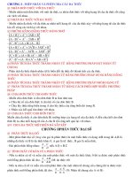
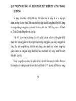
BC7000
MICROCOMPUTER
BURNER
CONTROL
SYSTEMS-
The
BC7000
"Blue
Chip" is an intelligent, microcom- The functions performed
by
the
BC7000, Fig. 54, in-
puter
baSad integrated control system.
It
provides all at the
clude: automatic burner sequencing, llama supervision,
functions
of
the programmable controllers like the R4140. status indication, tirsl-oul annunciation, self-<liagnostics.
Because
it
uses a microcomputer for control
and
logiC.
it
and energy conservation features. The system is
d9-
provideS levels
or
reliability, safety,
funcliOl1al
capability, signed for automatically fired gas, oil, coal, or combination
and features that are beyond the capacity
at
c(l(lventional
fuel
single
burner
awlications.
With
lhe
awroprlate
plug-
electromechanical or discrete solid slate controls.
1he
in
PM720
Program
Module,
the
BC7000
will prOVide
any
BC7000
can
be
used to upgrade ltle A4140 or R4150 in
standard
burner
program
sequence,
liming,
and
required
mOSl
applications, and mounts on the same Q520
iring
features.
Table
VI
lists
the PM720G, L
and
M
program
5Ut:base.
modules
that
are
available
for
the
BC7000L
_
_________
-
PLUG·IN
PROGRAM
MODULE
(PM720j
PLUG-IN
AMPUFIER
_
AMPLifiER
COMPARTMENT
DIE
CAST
MULTI-FUNCTION
METAL
CHASSIS
ANNUNCIATOR
DISPLAY
SEQUENCE
STATUS
LIGHT:
}
~~~~~~~E
HOLD
IGN
TRIAL
FLAME
ON
RUN
POSTPURGE
ILLUMINATED
RESET
BUTTON
'RUN/TEST
SWITCH
E1201
FIG.
54-BC7000
MICROCOMPUTER
BURNER
CONTROL
SYSTEM.
TABLE
VI-PM720
MODELS
AVAILABLE
PM720
PREPURGE
TIMJ~G
(sec)
EARLY
SPARK
TERMINATION
FLAME
ESTABLISHING
PERIOD (sec)
POST-
PURGE
TIMING
(.sec)
I~TER·
LOCK
CIRCUITS
FIRING
RATE
CIRCUIT
ENERGY
SAVI~G
PREPURGE
(ESP)
PILOT
MAI~
L1030
1200'
30
y~
10
10
or
15
15
Preignition,
LOCkout.
Lan' Fire,
High Fire
'-wn
Modu-
laling
y~
G2005
'"
y~
10
100~
15/30
15
Preignition,
Running,
low
Fire
4-Wire
Modu-
IaUno
\.:12013
10
or
Inter-
mittent
M2002
30190
&
y~
,
'0
"'"
Inler-
mitlent
15
Preignition.
Running,
low
Fire
2-WIIlI
lsolatecl
O~,OFF·
ON
Contacts
M2036
30f7
&
Preionili::>n,
Running
None
.&
90
seconds:
30
seconds"
lelTT1inaI
15
is
jumpered
to
terminal B.
.&.
15 seconds;
30
seconds"
tem1inal15
~
jumpered ll:llBrminal
B.
&.
30
seconds: 7 seconds if terminal
1S
is
jump8(ed
to
t&rminal
B.
165 7'-9755B-'
FEATURES
The
BC7000 Microcomputer Burner Control System
perlorms all customary flame safeguard functions while
providing sitTrificant advancements In the areas
01
safety,
annunciallCll,
selr-dlagnosi~
and energy conservalion.
SAFETY PROVISIONS
Since
CorTDustion
safety is the main task
or
the BC7000
MicroCOf'l'PJter Burner Control System, 60 percent
of
the
running lime of.ltle microcQmputer
Is
devoted to dJing
15
different
bJl
OVQfJC\Wing
safety routines. More than
400
safety checks are
performed'
every second that the
BC7000
Is
In
operation
10
check the performance
of
the
to-
tal Burner Control System (microcOlTP-lter operation,
pr~
gram memory and executiOfl, liming functions, input
signals, logic operations, and output commands). This
as·
sures thai the BC7000 is able
to
do Its fundamenlal com-
busliCll safeguard lask with the highBSt degree
of
safety
available.
Safety fea!ures include:
DynamiC
self check logic
Expanded
self start check
Circuit status monitoring
High fire purge and
low
fire start-switch tests
Verified spark termination
T~r
resistant liming and logic
Mandatory purge
DYNAMIC SELF·CHECK SAFETY CiRCUIT
The principal ,safety provision
of
the BC7000
Micr~
computer Burner
ControT""'SYSt8m
Is
its Dynamic
self
O1eck Safely Circuit: a totally independent mulli-element
safety circuilthat supervises microco.'T1puter pertormance
to
ensure ils proper operation. The microcomputer tests
itself and ils associated
harctvvare
with comprehensive
safely routines. Any malfunction will either be detected by
the
microcomputer to cause a safely shutdown or cause
lhe Dynamic Safely Relay'to de-eneigize ALL safety criti·
cal
loads.
EX'PANDEO
SAFE START CHECK
lhe
conventional safe start check is expanded to in'
cll.lde a flame signal check dur.ing si'anctJv
(Off-CyCle)
ar\d a
preignition output circuit check.
- Off-Cycle
(Standby)
Flame
Signal
Check
is apro-
vision Ihat monitors the sfatus
of
lhe flame detection sub-
system (flame detector and amplifier). If a flame simUlating
condition as a result
of
marginal or faulty flame detection
components (or actual flame) exists, a hold code will be
di!Clayedand system starlup will
be
prevented.
11
the can-
dilion continues for more than 30 seconds, a lockout will
occur and be annunCiated.
-Preignition
Output
Circuit
Check
makes sure
that all safely
crilicalloads
(valves
ard
ignition terminals)
are ct&energized just before Ihe ignition trial.
At
the
end
of
prepurge (belore entering the ignition trial sequence)
the
DynamiC
Safety Relay (lK1) is energized and the ignitor,
pilot valve, and main valve terminals are immediately
checked for Ihe
de
energized cOndilion. A safety shut-
down
wi)J
occur if any of these terminals
are
energized.
CIRCUIT STATUS MONITORING
-Dynamic
Input
Check
examines all system
irpJt
circuits at the load terminals
to
assure system Capability to
recognize
the
true status
01
exlernal controls,
IimJls,
and
Interlocks. ThIs self-check
is
accomplished thousands of
IiITl8S
every minute,
If
any Inpuf fails the test, the micro-
corrpuler will 8Xecute a safety shutdown and annunciate
lhe
awrcpriale
tault code.
-Closed
loop
logic
Test verifies the integrity of all
safety critical output circuits
~erminals
5,
6,
7,
and
18).
An
ilTVllediate safety shutdown is executed If these loads are
not properly operated.
-Dynamic
Safety
Relay
Test checks the ability
or
the
lK1
relay
to
open and close. During prepurge (with
power
10
lerminal
3)
lhe circuit slatus monitor Immedialely
~downstream·
of the
1K1
Is
checked
10
verify the de-ener-
gized stale.
At
lhe end
or
prepurge (but before igniliOfllri·
als)
the Dynamic Safety Relay is energized and both the
~tream
and downstream circuit status monitors are
checked. A miscompare will resull in a safety shutdown.
HIGH FIRE PURGE AND LOW FIRE
START SWITCH TESTS
-High
Fire
Purge
Switch
Test
(PM720U examines
the purge position interlock switch at the moment the firing
rate motor
is
commanded
10
the high fire position.
11
the
swilch is
bypassed, welded, or otherwise prematurely
closed, the system will aulomalically add 30 seconds
loal·
low the firing rate motor
a,cX:1ilional
drive time \0
rB2,ch
or
near the open damper poSiliOfl Defore 'starling' the \:lurge
liming. Otherwise purge liming starts when the high fire
switch closes.
-low
Fire
Start
Switch
Test
examines the low lire
start swilch
at
the moment prepurge is over. If lhe switch is
bypassed, welded, or Olherwise prematurely
Closed,
the
system will automalically
acX:130
seconds to allow Ihe fir·
ing rate motor
acX:1itional
time
to
reach or near Ihe
lOw
t'fe
start posilion prior to ignition trials, Otherwise ignilion tri-
als start atter
the
low lire switch closes.
SUPERVISED
lOW
FIRE START
The low fire
sian
switch
is
monitored before entering
the ignitiOfl trial and during the last 5 seconds
of
the trial for
pilot flame.
VERIFIED SPARK TERMINATION
The ignition terminal is monilored to assure early spark
termlnaliorl
(5
seconds ignitiorl and pilot
~nd
5 seconds
·pilolonly").
TAMPER RESISTANCE
All safety
and
logic
timlnQS
are inaccessible and cannot
be
altered or defeated.
MANDATORY PURGE
If lockout occurs after the initiatiOn of ignition trials (or al
any time during the sequence that the fuel valves may
have been energized) a mandatory postpurge period is
~p?sed.
166
FIRST-OUT
ANNUNCIATION
AND
SELF-DIAGNOSTICS
Control
and
burner system startup, troubleshooting,
and
ref)airare aided through i.QleQraLBC7000 Burner Con-
trol System first-out annunciation
and
self-diagnoslic
functions.
-First-out
Annunciation
repJrts the cause
ot
a
safety shutdown (with
afault
coda)
oc
identifies the cause
of
a failure to start
or
continue in the burner control se-
quence (with a Hold code). All field input circuits are moni-
tored, including-lfis·"flall:te signal amplifier
and
firing rate
JXlsilion switches. The system
disli~uishes
seven mocles
of
flame 1ailure
and
detects
and
annunciates diHiculHo-
find
intermiltents caused by bouncing
or
marginal limits
·and interlocks.
-
The
Multl-functron
AnnunciatOr
DIsplay
sllows
the elapsed time during prepurge, ignition triats,
and
postpurQesequences.
As
an ad:litional service aide it pro-
vides the time in sequence
if
a safety shutdown occurs
during
a time
period
(the hold!falJlt code
and
lime
are alter-
nately displayed).
-_.
-Self
Diagnostics
ad:l
to the first-out annunciation
by
allowing
the
BC7QOO
Microcomputer Burner Control
System to distinguish between field (edernal device)
and
internal (system related) problems. Faults associated with
either the flame detection
s~ystem,
plug-in program
module,
or
the system chassis are isolated and repJrted
by
\he Multi-function Annunciator Display.
-
Sequence
Status
LIghts
{LEOs} prOvide JXlsitive
visual indication
ot
the program sequence: STANDBY
!power on), PREPURGE, HOLD, IGN TRIAL, FLAME ON,
RUN, POSTPURGE, and, through the illuminated reset
switch,
safety
$hutoown
(lOCkout).
ENERGY
CONSERVATION
Unnecessary
and
wasteful purge related heat losses
are significantly.rE!duced
by
the'
program intelligence
of
the
BC7QOO
Microcomputer Burner Control System.
-Energy
SaVing
Prepurge
(ESP), ekclusive to
some PM720L sequences, pre ents blower
~ration
at
startup until the
damper
reaches the purge
JXlSiliOO
(high
1ire
purge
SWitch closed). This prepurge sequence change
saves apprOXimately 3'00,000 Btuh
per
boiler horsepower
annually
on
cycling boilers
in
typical heating applications.
-Energy
SavIng
Intelltgence
terminates burner!
blower
operation
and
energizes
Ihe
alarm circuit
wherJ
ever
the high fire
purge
switch (PM720L model), the low
fire start switch (all models axcept PM720M2010).
or
the
running interlocks (PM720G, M modelS) fail to close after a
suHicient time delay.
INSTALLATION
OF
A BC7000
The basic staps in the installation
of
a BC7oo0 are
(1)
mounting
the wiring subbase
(2)
wiring to the subbase,
(3)
installing the flame detector,
(4)
performing the static
checkout,
(5)
installing the programming module,
and
(6)
mounting
the programmar. These steps will
be
de-
scribed generally in this section. Follow the appliCable in-
structions prOVided
by
the burner manufacturer in addilioo
10
those
ot
the instruction sheet for the particular modal
when Installing the system.
MOUNTING
THE
WIRING
SUBBASE
Install the BC7000 where the relative humidity never
reaches
lhe
saturation point. Condensatioo
at
moisture
on
the BC7000 may cause 1alse flame readings
and
cause
safety shutoown
(lOCkout)
or
prevent the bJrner from
starling.
The
BG7DOO
is
not
deSigned
10
be
w6alhertllflL
If it
is
installed ouldoors,
il
must
be
protected. Also,
do
not install
the
BC7DOO
where il
could
be
SlbJecl to ekcessive vibra-
tion (greater
than
0.5
OJ.
Do not mount the wiring
sul::::Oase
horizootally with the
knife-blade contacts JXlinting
down.
This
aUO¥tS
the
accl l'
mulation
of
moisture. The standard vertical posllion is pre-
ferred; any other position decreases the maximum
ambient temperature rating.
$elect the location
on
a wall
or
instrument panel. Be
sure to allow clearances
for
servicing
and
removal
of
the
BC7000. For surface mounting. use ·the back
of
the sLb-
base as a template to mark the 4 screw locations.
WIRING
TO
SUBBASE
(FIG.
55)
Wiring
connections
for
the
BC7QOO
diHer from those or
other controls that
mount
on the Q520A Subbase. Fig. 55
shows the pr~r subbase wiring
for
the BC7000L with the
PM720L1030 program module.
Disconnect the JXlwer
sU~ly
before
t:::eginni~
installa-
lion
to prevent electrical
shock
and
equipment damage.
All wiring must comply with all applicable electrical ccxies,
ordinances,
and
regUlations. Use NEC Class 1 (lIne vall-
age)
wiri~.
r IMPORTANT
00
not
run high voltage ignition transformer wires
in the same conduit with the flame detector wiring.
Make sure the loads
00 not exceed the terminal ratings.
Refer to the label
on the
BC7QOO
or
10
the specifications
sheet.
Check the power supply
circuit
The vollaQ9 and
tre-
~cy
tolerances must
match
thOSe
of
the BC7000 and
PM720.
00
not
connect the
BC7QOO
to a
J:Xl'MIr
SLWly cir-
cuit which is SltIject to line voltaQ9 varialions, such as
would occur with ON·OFF switching
of
heavy loads. A
separale power supply circuit
may
~
reQlllred for
the
llame safeg.Jard control.
Adcl
Ihe
rElQUired
disconnect
means and overload protection.
INSTALLING
THE
FLAME
DETECTOR
NOTE: Table
IIlisls
the flame detection systems available
for
use with the BC70Q0 Mic·rocomput9l' Burner Control
System. Maka sure you are using
the
correct corrblna·
lion
of
ampli1ier
and
flame detector(s).
Proper flame detector inslallation is Ihe basis
of
a safe
and
reliable flame safeguard Installalion. Refer to the
In-
slructions packed with the flame detector
and
the bJrner
167
71·97558-1
manufacturer's instructions. Follow the instructions
car~
fully
to
make the
basi
possible
awlicallon
of
the flame
deteclor.
Keep
lhe flame signal leadwires from the flame detec·
lor
to
lhe wiring
Sl
t:tlase
as
short as possible. capaci-
lance increases with leadwire length, reducing the signal
strength.
The
maximvrn permissible leadwire length de-
penels on the type
01
flame detector, leadwire, and con-
OJi\. the ullimale limiting factor
In
the flame slgnalleadwire
lel"lQlh
Is
lhe flame current
(see
Table
V).
SPE"CIAL
CONSIDERAll0NS
FOR A C7012E, F
The power to the mite leadwlres must
be
120 Vac; this
is the power supply tor lhe
OJ.)8ralion
of
the self-checking
BC7000L/PM720L
1030, PM720L1139,
PM720L2020 WIRING DIAGRAM
.,
-1
r~";:~~'O;;";;O=~LJL;::::
INTERRU"ED
I-
~
, )
PILOT/IGNITION
I
'-'"
-1J
~'~'~"~'~O~"O~:-LJL",~
INTERRUPTED
t-
-{'
J
PILOT I
~
&
fROVIOE
DI~[ONNEn
"'ANI
NO
O"'ERLa
o
PRaTlCTloN
A'
REQUIREO
& IN
SO>OE
IHSULL.'\TloHS
THE
LOW
fl
IETWHN
T(""'NAL l
LI
AND
II.
"""
FIG.
55-WIRING
THE BC7000L FOR USE WITH THE
PM720l1030
PROGRAM
MODULE.
168
shutler. The 120 V for the shutter is obtained automatically
at
terminal 17
of
the
BC7000
through switchif1Q action
within
the
plug-in
R7247C
or
R7476A Flame Signal
Amplifier:
.
USING
REDUNDANT
PARALLEL
C7012E, F
DETECTORS
For
a
flame
that Is
diftlcull
10
siQht,
uSif1Q
2 parallel
C7012E
or
F
'~lame
Detectors may r€ldJce the occurrence
01
nuisance
shutdowns. If only one
of
the parallel detec-
tors loses-\.t.le
1Iamesignal"the
other
may still indicate
the
presence
of
the
flame
and keep the
burner
running. A
llame
simulating
failure in either
of
the detectors will cause
the
burner
to
shut
down. A m8J(imum
of
two C7012E de-
tector shutters may be
wired
in parallel
to
the same termi-
nals
on
any
BC7000
(if
the voltages malch),
STATIC
CHECKOUT
(TABLE
VII)
Atter checking
aU
wiring,
pertorm
this
checkou( before
installing the BC7000
on
the
sutbase.
These (esls ensure
thallhe
Q520A
Wiring
Sut:basels
wired
correctly,
and
lhat
the external controllers, limlls, interlocks, actuators,
valves, transformers,
motors,
and
other
devices are
q::>er-
atif1Q
properly.
Remember that line
"ollage
is present on most termi-
nals when power is
on,
so be extremely careful when per-
forming
these tests. Follow the Instructions
In
the
inslruction sheet for the
8C7000
very carefully. Perform
only those lests
designated
10r the specific BC7000U
PM720 model
being
tested.
Perlorm
the tests in
lhe
order
listed.
TABLE
VII-STATIC
TESTS OF EXTERNAL
DEVICES
TEST
NO.
PM720
MODELS
TEST
VOLT-
JUMPERS
METER
NORMAL
OPERATION
I/.····.''Z/.»>·//
WARNING'
/:'./
,',"'
.
I
II
Make sura all manual fuel
thutoff
"al"es
ara
clond.
I
1
All
None
L1.l2
2
All
No,.
1&[2
3
All
Noo.
~[2
4
All
L1"
3-[2
•
All
LH8
-
Lina
\'Oltage
at
lermin.a!
L
1.
Line
'odtalle
at
termin.a!
16.
Line
oltage
at
terminal
4.
1.
Burner
mobr
tlan
Of
blower)
.
""".
2.
Une
oltagtJ
at
terminal
J
with-
In
10
SllCOtllls.
Ignition SPlrk
(d
ignition
trans-
former
Is
connected
10
terminal
1m.
IF
OPERATION
tS
ABNORMAL,
CHECK
THE
ITEMS
LiSTED
BELOW
IMPORTANT
Low
hJel
pressure
Hmits.
~
uSEld.
could
b8
open
Bypass
Itlem witl
jumpers lor
the
rest
01
Itle
Sta~c
Tests
Cd
required).
1.
Masler switch.
2.
Pow-er
is
connected
10
the
master
swi1I::h.
3.0"erbad
protecoon
(hJse.
circuit
breaker,
elc.)
haSl
rol
opened
the
po¥f8r
line.
1.
Limits.
2.
Burner controller.
1.
Preillnition inlerbc:ks.
1.
Bumer molor circuit
a.
Manual S'Mlrtl
of
-tlumer
motlr
.
b.
Bumer
=b'
., ,
supply,
,
protection, and i'ilaner.
c.
Bumer motor.
2.
Running
or
lockout
inter10cke
(n:luding
the
AirfloW
Switch).
1.
Wetch
lor
lpark
or
listan for
buzz.
a.lgnition electrodas are
clean.
b.lgnition transformer
16
okay.
t. Watctl lor spark
Of
listen
lor
buzz,
a.lgnition electrodes are cleall.
b.lgnibon transIonner
la
okay.
2.
Listen lor click or leel
head
of
valve
b'
aeli-
"aOOn.
a.Actuator
(i1
used).
b.
Pilot "alve.
5
All
L1·5 -
1-://><>'///.<%/:''w;''~~lN~///
//////,/,'1
I Make aure all mlnuaJ
tull
thutoft
val"e5
Ire
closed. I
1.lgnitioll Ipark
(d
ignition
trans
former is conneclad
10
laltTlinai
').
2.
ALJbnatic
pilot
valve
opens
(d
COnnetled
10
larminal 5).
NOTE:
RelSf
10
"";ring
diagram
or
the
gys\lIm
beinCjl
tested.
169 71·97558-1
TA13LE
VII-continued
,
TEST
PM720
VOLT-
TEST
IF
OPERATION
IS
ABNORMAL,
CHECK
THE
ITEMS
LISTED
BELOW
NO.
MODELS
JUMPERS
METER
NORMAL
OPERATION
'.
Alt
Same
as
TEST
No.
6 (II using direct spar)( ig·
sarr.
as TEST
No.
IS
lor oonnec-
7
-
"
ti::nl to terminal
5.
(If using direct nItion, checll the 1st stage
fulJ!
valve(s) i
5'pal1l.
19nitbn,
chec~
,.
sl6Bd ol1he prot var"e.)
stage
fuel v'/vlJ(S)
insle.d
""
01
the
pilot valwl.)
All
L1'7 AlJb'nalic main
1u.1
valVe(s)
1.
Usten lor
and
observe operation of
the
opeN.
(It using direct spar)( Ignl·
8 -
main fuel valve(s) and
aC1Ualor(s).
.
tixl
OIl
a
m:>da\
ith InlelTrlittent
2. Valv9(s) and actualor(sj.
.
-,.
pilot on lerminal 6. check
the
op-
tional 2nd stage fuel valve.
,
""""
.J
9
U-S!
AJann
rlf
u$Eld}
turns
on,
All
1.
Alarm.
-
13-l2
Flmg rate m:rtor drives open: 1.
low
fire start !M'Itch,
10 PM720
"
'nd
zero volts
11.1
terminal
13
after
G&:L
Models 2. Firing rale molDr
Rnd
transtormElr.
10-11
ITIJt:lr starts driving open,
13-l2
firing rale molDr
dri'-Jes
clo5ed:
1.
Low
fire start switch,
11
PM720
"
line voltage
11.1
lerminal 13
aftElr
2.
Firing rale molDr and transformer,
14-11
G&L
MOdels
,n'
rJ'lCIb'
is
11.1
loW
fire
~sttior"l.
15-l2
Firing rate motor drives open:
1,
High fire
purgl
switch.
PM720L
12
"
~I'le
vottalle
at
terminal 15 after 2.
firing
Tale
rn::>lDr
and transbrmer.
10-11
ModElls
,n'
~
is
11.1
high fire position.
15-l2
Firing
rate
m:rtor drives closed:
1.
Low
fire stan switl:h.
PM720L
13
"
zero \'tilts at Iermine! 15 after
mo-
2.
Firing ratil molDr and translortner.
14-"
ModElls
,n'
fOr
starls driving closed.
"
1.
Rilsa
set
point
01
se.'leS
90
1. Series
90
controller.
-
12·11
""720
2.
Firinll rate molol" and transformer.
Gt L
ModElls
controller-firing
=""
&h:>uld
drive toward
""
·open.·
2.l.owef S8l point
01
slJries
90
'controller - firing
rate
=""
should drive toward
·closed:
1.
Darnper
rn::>lOr.
Models
ith
PM720M
L1-11
" damper motor
is
used, motor
15
drives damper open,
Open Damper
Conto,~
L,.
1.low
fira stan switch.
MOdels
with
PM720M
II
damper molDr
is
used. spring
13-l2
retum dli'.'Bs
rJ'lCIb'
and damper 2. Damper m:rtor.
"
closed;
hne
yottage et lerminal13
Contacts
Open
Oampe~
aftBr
rJ'lCIb'
is
alloW
fire posftbn.
"
11
damper
rn::>tor
is
used. motor
1.low
fire $tan switch.
PM720M
13-l2
Ll"
drives open:
:tlJro
volts
at
terml·
2.
Damper molor.
Modela
ith
,n'
naI 13
atLer
motor starts driving
Open Oampar
~
',1
1
Coma",
,""'.
Final
All
.f5IB.
;;;;
I]
~
~
UJXln
anlpleling
these tests, open
the
master switch and
rElTlOWlall
rest jumpers
from
the sub-
base
termifl8lS;,
A&J
remove
bypaS$
jumpers
fran
the
low
leVel
fuel pressura limits
(If
used).
INSTALLING
THE
BC7000
(FIG.
56)
Open
the
master
switch
to
remove
power
from
lhe
sub-
base
terminals.
Also,
make
sure
lhat-
-
there
are
no
bare
(unlnsulated)
wires
In the SUbbase.
-the
wiring
10
any
terminal
does
not
touch
any
other
terminal.
-
no
subbase
iring
is
projecting
beyond
the
terminal
blocks.
-the
iring
base
does
not
interlere
with
the
connoctors.
Tuck
af!
iring
in
against
the
back
of
the
subbase
SO
II
cbes
not
interlere
Hh
the
contacts.
To
install
the
8C70oo,
engage
the
chaSsis
hinge
brack·
ets
with
the
pivot
pins
at
the
tx:lUom
of
the
subbase.
SW'lng
the
chassis
inward
unW
the
spring
connectors
engage
lhe
knife{)lade
contacts.
Push
until
fhe
contacts
are
tully
ert-
gaged.
Tighlen
the
chassis
retaining
screw
securely.
170
KNIFE·BLADE
CONTACTS
{<OJ
SPRING
CONNECTORS
CHASSIS
RETAINING
SCREW
,
/
WiltiNG
~U
••
"'SE
PIVOT
PIN
«)
HINGE
9R.o,CKET (2)
u,
FIG.
56-MOUNTING
THE
BC7000
ON THE
SUBBASE.
INSTALLING
THE
PM720
PROGRAM
MODULE
The
plu~in
program module contains all
01
the logic in-
structions
which
determine the operating sequence
of
the
BC7000 system. This allows one universal chassis
10
per·
lorm
any standard burner program.
AU
thai need
be
changed is the program module
and
suttlase
wiring.
To
install the mcdule, remove the amplifier comparl·
menl cover
and
remove the flame signal ampUfler (if pre-
sent). Insen the program modlJle into the opening in the
side
01
the amplifier companmElf1t
as
shown In Fig. 57.
Now, reinstall the flame signal amplifier
and
the compan-
ment cover.
FIG.
57-INSTALLING
THE
PM720
PROGRAM
MODULE
IN
mE
BC7000.
INSTALLING
THE
PLUG-IN
FLAME
SIGNAL
AMPLIFIER
(FIG.
581
1.
Remove the amplifier compartment cover.
2.
Grasp
the flame signal amplifier with the monogram
toward
the ootside face of the amplifier companlTlEll"ll.
Align
the
circuit
board
with the keyecl receptacle in the
171
BC7000 chassis. NOTE:
If
you are installing a small ampli-
fier, align its ends with the 2 lines alongside the receptacle
on
the BC7000 chassis.
3.
Push
lhe
flame signal amplifier into the keyed recep-
lacle until the circuit
board
is
fully
inSEIned
and slide it un-
der the holddown clip. Make sure the amplifier
is
securely
in place.
4.
Replace the amplifier cover.
USE OF THE
RUN/TEST
SWITCH
(FIG. 54)
The RUNITEST switch
is
located
on
the side
of
the
BC7000 Microcomputer Burner Control System Chassis.
The RUNITEST switch performs the following func-
tions in lhe operating cycle:
1.
The RUNITEST switch will
stop
the
5eCJjence
in
the
PREPURGE,
at
low
fire. jusl before ignition trials
~f
it
is in
the TEST position
prior
10
this point). SIq:Qing the system
at this point allows adjustment
of
the firing rate molor
and
damper linkages.
2.
The RUNITEST
swilch
will Slop the sequence 1iJr·
ing
the first B seconds
of
the PILOT IGNITlON trial. This
allows testing
for
spar\(
pick~
when the system
is
used
wllh
an ultraviolet sensor. When
stopped
in lhis position II
is possible to
perform
the pilot turnd::lwn test. A BC7000
internalflam&<lUl:
limer
Is actlvaled that will cause a safety
shutdown
if
the pilot flame signal
Is
lost tor
30
seconds.
3.
If
the RUN/TEST switch
Is
thrown
10
the TEST posi-
tron dUring the BURNER RUN
period
of
the cycle. the
8C7ooo commands the firing rate
molor
to drive
10
the low
fire position. This Is useful
tor
holding
at
low
fire tor cold
startup
(as
recommended by most boiler manufacturers).
NOTE: When the BC7000 is
swilched
to the TEST mode, it
will Slop
and
hold
at
the next RUNITEST switch test
point in the operating sequence until the RUN{TEST
switch is retumed
10
lhe
RUN posltion. MAKE SURE
THAT THIS SWITCH IS IN
mE
RUN POSl110N BE-
FORE LEAVING
THE
INSTAUATlON.
71-97558-1
SMALL
AMPLIFIER
E11U
BC7000
CHASSIS
LARGE
AMPLIFIER
FIG.
58-INSTALLING
THE PLUG-IN
FLAME
SIGNAL
AMPLIFIER.
CHECKOUT
AND
TROUBLESHOOTING
Befofelhe
system is
pul
into
service the operator must
perform all applicable lests listed in the Checkoul
Sum-
ma/y
below and iJl'rf
others
required by the burner manu·
facturaL Refer
to
the
description
of
each lest in the R414{)
section.
lnslruclions
for
the
lests
listed
are
in the instruc-
Iioo
Sheer
for the BC7000.
To
IroublElSl'O:>I
the l?C7000. refer
10
the section on
Troubleshooting Flame
safeguard
CQllrols
and to the
irr
slruclioo Sheet for the BC7000.
Before starting the
burner
the first lime, make
SUfe
all
1U&I
shUloff valves
are
Closed. Also,
be
sure
to
heed
thefol-
towing warning.
Do
not
allow
fuel
to
accumulate
In
the
com-
bustion
chamber.
If
fuel
Is
allowed
to
enter
the
chamber
for
longer
than
e
few
seconds
without
Igniting,
80
explosive
mixture
could
result.
It
Is
recommended
thet
you
limit
the
trial
for
pilot
to
10
seconds,
Bnd
limit
the
attempt
to
light
the
main
burner
to
5
seconds.
In
any
case,
do
not
exceed
the
normal
IIghtoff
time
specified
by
the
burner
manufacturer;
close
the
manual
fuel
shutoff
valvas
If
the
fleme
Ie
not
burn·
Ing
et
the
end
of
the
specified
time.
CHECKOUT SUM
MARY
The following lis! summarizes the checkout lests
re-
Q.Jired
for each type of installation.
• Prelimina/y
Inspeclion-au
inslallations.
• Flame Signal Measurement
-all
Installations.
• Initial Lightoff Check for Proved
Pilot-all
installa-
lions
USing
a pilot.
• Initial LightoN Check for Direct Spark Ignition of
Oil-oil
burners nol using a pilot.
• Pilot Turndown
Test-all
instaliatiOf'ls using a pilot.
• Ignition Inlerference
TesI-all
installations using
flame
rods.
•
Hot
Refracto/y Saturation Test
-ailinstaliallons
US-
ing infrared (lead sulfide)
flame
deteclors.
• Hot Refracto/y Hold-in
Test-all
installations using
reclifying photocells or infrared (lead sulfide) flame
detectors.
• Ultravlolel Response
Tesls-all
inslallatlons
usinQ
ultraviolet flame deteclors.
• Flame Signal wllh
Hot
Coobuslion
Chamber - all
installations.
OPERATING
SEQUENCE
The fOllowing q:l9raling sequence is for a BC7000U
PM7Z0L1030 Microcompuler Burner Control System;
it is
included here for
exal11J(e
only. For ofher mcdels
of
lhe
BC7000, refer to the installation
sheet provided with
trae
device. Fig. 59 illustrales the q:l9tation
of
the system.
172
DIGITAL
DispLAY
,
H"'ND!
~
PQ£'U~
"
~
HOLD
::i '<:iN.
TR
'"
•
:=I
~
",~
"
-:.
"
~uN
WI
"C~,
."
O'[~"'T1NG
CONrROL.5
,-,
INrtRLotl<1
.L
~
~AF
,
"CNAL
~T'"
"'
BC7000LlPM720L1030, PM720L1139, PM720L2020
aD
ill
:TO
[J[J
10
t?a
,~'i
ffi
[J!J
,,'
"
0
0
,
"
"
.,
•
__
01.
,'
,'
0
0
0
0 0
0
0
0
0
,.
0
0
6'
"
0
0
0 0
0
0 0
",
._'''.lO.
0
0
0
.,
,y"
0
0
.~oo"
O!
0
0
"
.J
i)
"AlII
\I"LV~
f'\.AIIl. PROIII"':'
@lO@
@T~
'
'1'
"
!
'0
lEC
I
u""'"
0
8'1.110"1'."
CoorrllDO Ll.
C\.C&ICO
~l)
TO
,.
,
u:>eKour
'N'TEALoc;oa
CLOSED
I.
M
I
•
[co
~E'G"'T'OI<'InVIL.DCll.SCLOUO
If
TO
,
,
1I1lill
nlllllWlTCII
CLOSED.
~oJ
0
T
o@)
(0)''1
0
T
o(\
!l
I
:I
FII:101.o.,,""CII[CO\
{
"."
1['_
'~w'TCHING
GTO@
"'O'OA
C"ON
,
i
,
@roG
6
f~l
O",,-AY"
8
N'"
ou
c
rHE
Au"
'(11'01'.
~Y~TE'"
'''''A''''
'N
flUN
Ai
LO""
"'",NEA
CONTAOLU~
CO,H"'CTt
AAE
CLO'EO.
,2,
,
'OON"~
LO"
FIAl
nAA'
~wITCH
CLO§£5
HOLD
L'CH'
TUII"~
OFF
out,",(
t"'tA'
.<ON
TA''''L,
.oFf
EA'
~.C
DEL"'Y
110
FDA
'''''oLlOI.
.'u
.
0
"
.:>
'.,
"~
" ,
0
0
0
0
0 0
0
0
0
"
'
L
*-,
",
._fL""
••
0'
0
,
"
'
0
0 0
_~flIOTOII
0)
'Gl'I.Js
SEC
IG/tJ"l.f.'
1IG'Io(C.
'JI
IGIl.,ol'LT. Z
"~U.
0
FIG.
59-OPERATION
OF THE
BC7000l
WITH THE
PM720Ll030
PROGRAM
MODULE.
173
71-97558-1
,
~.'
STANDBY
The
BC7000 Microcomputer Burner Control System is
read! to start
the
~raling
sequence when the burner
controller closes.
All
other controls, limits, and Interlocks
are in
the
oerrect
~raling
slate.
The
STANDBY se-
QJence status
1Ig,1
Is
on
and the Multi-function AnnuncIa-
tor Display is blank.
NORMAL STARTUP
1.
Wilhpowerawlied
(the limits, conlroller, preignition
interlockS
CloSel;i,
and
no
flame signal
present)
the
burnerl
blower motor (terminal
(l)
is energized and the firing rate
motor (if
usedj' drives (he (he high fire
(~n
damper) posi-
tion.
The
Mulli-funclion Annunciator Display Shows
~OO."
the STANDBY status Ughlturns off, and the PREP URGE
and
HOLD slatt.5
U~ts
turn on.
NOlE:
If Ihe
hl~
tire purge switch is prematurely closed
ijurnperedbr welded') an additional
30
seconds
of
drive
time is aoctecn6 allow the firing rale motor
10 reach or
near
the
hj~
fire posilion before entering the prepurge
counh.~.
During this e)(lra lime,
lhe
PREPURGE and
HOLD status
Iig,ts
remain on and the Multi-function
Annunclalor Display remains at
"00."
2. When
lhefiring
rate motor reaches
thehl~
tireposi-
lion, the
hl~
fire purge swilch
closes,
the
HOLD status
li~t
lurl'S
off,
and
the 3O-6econd proven open
damper
prepurge starts.
The
Multi-function Annunciator Display
starts counting from
"OO~
10
"30.·
3.
The
lockout interlocks must close
by
10 seconds inlo
the prepurge (proven presence of airflow) or safety shut·
down will occur. •
4.
At
the camplelion
of
the 3D-second prepurge these-
QJence
is
st~
and
Ihe firing rate molor drives to the
low fire position.
The
HOLD slatus light comes on and the
Mulli-func!ion Annunciator Display stops counting.
NOTE:
If the low fire start switch
is
prematurely closed.
(jumpered"
or welded) an adclltional 30 seconds
01
drive
lime ls
aci:Jed
to allow the firing rate motor to reach or
near Ihe low fire position
be~ore
slarling the ignition tri-
als. The MUlti-flMlciion Annunciator Display shows
"30'
and
lhe HOLD status lighl is on.
.5. When
Lhe
firing rate motor reaChes the low tire posi-
lion, the low fire start
swilch
makes and allows the se-
Q.Jence
to continue. The HOLD slatus lighl turns
off
and
(atter a
5-seconc;l
delay
to
allow for complete motor travell
the sequence enters the ignition lrial period.
6. With the
low
tire start
SWitch
closed (and the RUN!
TEST switch
in
lhe
RUN
position) the ignition transformer
(terminal
18)
and pilot valve (terminals 5 and 6) are ener-
gized.
The
PREPURGE stalUs light turns off and the IGN
TRIAL stalus Iighl comes on. The MUlti-function Annun-
ciator Display starts counting from
"00·
to
"25-
seconds.
7.
~
soon es the presence
01
flame Is det8cled, the
FLAME
ON
status light comes on.
8.
5 secorx:ls Into the iQrlilion trial period the iQrlition
transformer (Iermlnal
18)
Is
energized.
9.
10 seconds into
-the
ignition lrial period
and
will,
presence
01
flame detected (FLAME
ON
status lighl
on)
the main fuel vatve (terminal
1)
Is
EnergiZed.
NOTE: If presence of flame
is
not detected at this time.
safety shutdown will occur.
10.
20 seconds into the iQrlition trial period Ihe pilot
valve (terminalS) is de-energized. This
Co~letes
the
10
second main flame establishing period.
11.
25
seconds Into the ignition trial period the pilot
valve (terminal
6) is cle-energized. This
c~tetes
lhe
15-second main flame BSIabliShing period. Control of the
firing rate motor
is
released
10
the modulating (series 90)
controller.
The
IGN TRIAL status light
and
lhe Mutli-func-
tion Annunciator Display turn
off
and
lhe RUN stalus
Ii~l
comes on.
The
BC7000
MicrOCOl'T\PUter
Burner Control System is
fJOw
In
lhe normal burner run
mode
of
~ration
ard
will
remain
so until an e)(lernal command direcls it to do
otherwise.
NORMAL
SHUTOOWN
1. When the burner controller
~ns,
the main fuel
valve (terminal
1)
is
immed"ialely cle-enargized",
and
the fir-
ing rate motor drives to the low fire position. The RUN
slatus light turns
off
and the POSTPURGE status Iighl
comes on.
The
Mulli-funclion Annunciator Display starts
cCllJnlin~
from
aoo~
to "1S
~
seconds. Atter the flame is
oul
the flame relay drops out and the FLAME
ON
stalus light
'urns off.
2.
Following the 15-second postpurge, lhe burner!
blower motor (terminal
8)
is cle-energized". The POST-
PURGE status light
and
the Multi·function Annunciator
Display turn off.
The
STANDBY stalus light comes on,
ending the Cf.I8rating cycle.
SAFETY
SHUTDOWN
(lOCkout)
OCCURS IF:
1. Flame signal
is
delected atter the first , 0 seconds
during prepurge
(FOO).
2.
The high fire purge switch fails to close wilhin 30
minutes atter Ihe firing rale
motor
is commanded to drive
10
the high tire position at the start
of
prepurge.
3.
A preignition inlerlock
~ns
during the prepurge
period.
4.
Flame signal is detected during the low fire hold.
S.
A lockout interlock opens during the prepurge (atter
10
seconds), ignition,
or
run periOd.
174