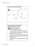
WILEY ANTENNAS FOR PORTABLE DEVICES phần 5 ppsx
Bạn đang xem bản rút gọn của tài liệu. Xem và tải ngay bản đầy đủ của tài liệu tại đây (818.14 KB, 30 trang )
104 RFID Tag Antennas
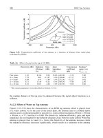
Transmission coefficient, τ(dB)
–30
–25
–20
–15
–10
–5
0
Free space
d
=
1 mm
d
=
5 mm
d
=
10 mm
d
=
15 mm
Frequency, MHz
800 850 900 950 1000
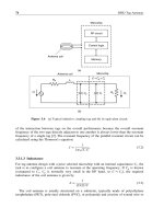
Antenna
Metal plate
d
Figure 3.32 Transmission coefficient of the antenna as a function of distance from metal plate
(calculated by IE3D).
Table 3.6 Effect of metal on the tag at 915 MHz.
Directivity (dBi) Radiation
efficiency
(%)
Gain
(dBi)
Input
impedance
()
Transmission
coefficient
(dB)
Reading*
range (m)
R
power−link
Free space 181 8184 094 33.65 + j427.00 −132 500
d = 1mm 779 067 −1397 3.20 + j336.00 −1717 015
d = 5mm 808 647 −380 3.45 + j372.50 −1227 082
d = 10 mm 811 1748 −053 4.49 + j404.30 −440 296
d = 15 mm 810 3001 288 7.08 + j423.80 −086 660
a
The system parameters were described in Section 3.3.1.6.
the reading distance of the tag may be enhanced because the metal object functions as a
reflector.
3.4.2.2 Effects of Water on Tag Antenna
Figures 3.33–3.36 show the characteristics of an RFID tag antenna which is placed close
to a water cuboid. As in the case of the metal plate, the antenna used is a folded dipole
antenna and is positioned parallel to and above a water cuboid measuring 250 mm × 80 mm
× 80 mm;
r
= 77.3 and tan = 0.048. The directivity, radiation efficiency, gain, and input
impedance are investigated for the different distances away from the water cuboid. When the
antenna is placed close to water (d = 1 mm), the directivity of the antenna increases while
the radiation efficiency decreases significantly, which results in a reduction in the antenna
3.4 Effect of Environment on RFID Tag Antennas 105
Gain, dBi
–40
–30
–20
–10
0
10
Free space
d
=
1
mm
d
=
5
mm
d
=
10
mm
d
=
20
mm
Frequency, MHz
800 850 900 950 1000
Antenna
d
water
Figure 3.33 Gain of the tag antenna as a function of distance from water (calculated by IE3D).
R, ohms
0
200
400
600
800
1000
1200
1400
Free space
d = 1 mm
d
=
5 mm
d
=
10 mm
d
=
20 mm
Frequency, MHz
800 850 900 950 1000
Antenna
d
water
Figure 3.34 Real part of the input impedance of the antenna as a function of distance from water
(calculated by IE3D).
X, ohms
200
400
600
800
1000
1200
Free space
d
=
1
mm
d
=
5
mm
d
=
10
mm
d
=
20
mm
Frequency, MHz
800 850 900 950 1000
Antenna
water
d
Figure 3.35 Imaginary part of the input impedance of the antenna as a function of distance from
water (calculated by IE3D).
106 RFID Tag Antennas
Frequency, MHz
Transmission coefficient, τ(dB)
–25
–20
–15
–10
–5
0
Free space
d
=
1
mm
d
=
5
mm
d
=
10
mm
d
=
20
mm
water
Antenna
d
800 850 900 950 1000
Figure 3.36 Transmission coefficient of the antenna as a function of distance from water (calculated
by IE3D).
Table 3.7 Effect of water on the tag at 915 MHz.
Free
Space
Directivity
(dBi)
Radiation
efficiency
(%)
Gain(dBi) Input impedance
(ohms)
Transmission
coefficient
(dB)
Reading*
distance(m)
(power-link)
Free Space 181 8184 094 3365 +j42700 −132 5.00
d = 1mm 399 578 −839 18130 +j77970 −1296 0.45
d = 5mm 244 303 −1274 3256 +j44150 −190 0.97
d = 10 mm 264 1417 −585 1636 +j41410 −047 2.52
d = 20 mm 461 3028 −058 1213 +j41790 −014 4.81
a
The system parameters were described in Section 3.3.2.7.
gain. In contrast with the metal plate, the water will always cause a reduction in the gain
regardless of the distance between the water and the antenna. As antenna is moved further
away, the antenna gain approaches the value obtained in free space. The input impedance
shows a smooth variation except when the antenna is very close to the water (d = 1 mm).
The effect of the water on the tag antenna and reading distance at 915 MHz are summarized
in Table 3.7. When the tag is very close to water, the reading distance drops significantly
to 0.45 m. As the tag is moved further away, the effect of the water is decreased and the
reading distance is enhanced.
3.4.3 Case Study
The results of measurements of the effect of various objects on a tag antenna are reported in
this section. The measurement set-up is shown in Figure 3.37. The effect of the objects on
3.4 Effect of Environment on RFID Tag Antennas 107
(a)
(b)
Reader
Reader antenna
1
Tag
3
42
R
d
Figure 3.37 Measurement set-up for evaluating the effect of objects on an RFID tag: (a) measurement
set-up and the selected items; (b) tags used in the evaluation.
the tag performance is evaluated by comparing the maximum reading distance. The tag is
attached to four common household items. The items are packed soft drinks, liquid detergent,
mineral water, and can-packed Coca-Cola. The first three items are categorized as lossy
materials which have different water contents in them. The can-packed Coca-Cola is chosen
to evaluate the effect of the metal object.
Two types of tag are selected for evaluating the effect of the four selected objects. One
is the UHF tag discussed in Section 3.3.2.7, and the other is a tag developed by Philips at
13.56 MHz (I-code I) which is commercially available. The tags are mounted near or on the
surfaces of the objects with different separations, d.
108 RFID Tag Antennas
Table 3.8 Measured results for HF tag attached to different objects.
Reading distance (R, cm)
(d, mm) Yeo’s drink Detergent Mineral
water
Canned
Coca-Cola
Remark (free space)*
03538340
13638380
53838380
10 38 38 36 23 41
15 39 39 38 25
20 39 39.5 39 27
∗
The reader used in the measurements is an Ormon V720S-BC5D4.
Table 3.9 Measured results for UHF tag attached to different objects.
Reading distance (R,m)
(d, mm) Yeo’s Drink Detergent Mineral
water
Canned
Coca-Cola
Remark (free space)*
00000
1 0.05 0.07 0.02 0.2
5 0.34 0.75 0.28 0.5
10 0.60 1.53 0.60 3.43 4.85
15 1.58 2.12 1.50 3.03
20 2.25 2.90 2.10 3.01
∗
The reader used in the measurements is SAMSys MP9320.
The results are tabulated in Tables 3.8 and Table 3.9. For an HF tag, the effect of water
is minimal: only a few centimeters variation in the reading distance is observed. However,
it is very sensitive to the metal object as it can be observed that the tag cannot be detected
even when it is 5 mm away from the metal cans. For a UHF tag, both the lossy materials
and metal object have a severe effect on tag performance. When the tag is affixed directly
on the objects, the reading distance is zero. The reading distance of the tag is observed
to increase when the tag is placed far away from the lossy objects because of their high
dielectric loss.
On the other hand, the variation of the reading distance of the tag on the metal
object shows a different trend. The tag cannot be detected when it is very close to the
metal can. However, the reading distance is enhanced as the tag is moved away, and
achieves the maximum at a specific separation (d = 10 mm). It should be noted that the
results obtained here are specific to this particular scenario and will vary for different
configurations.
References 109
3.5 Summary
This chapter has introduced RFID fundamentals and presented design considerations for
RFID tag antennas as well as the method of evaluating the performance of the tags. From an
antenna design point of view, RFID systems are preferably classified as near-field or far-field
systems. Near-field RFID systems usually use inductive coupling for the energy transfer from
readers to tags, and the load modulation technique for communication between reader and
tags. In far-field RFID systems, the energy is transferred by capturing the electromagnetic
waves, while the transmission of the information from tags to reader is achieved by using
backscattered signals.
Generally, an RFID tag antenna is required to be small enough to be attached to or
embedded into a specific object. It is often required to have specific radiation characteris-
tics such as omnidirectional, directional, or hemispherical radiation patterns. The cost and
reliability are the main considerations in mass production.
The antenna used in a near-field RFID tag is usually a coil. Such a coil is designed with a
prior selected microchip. The coil antenna is configured to provide the inductance required
for the circuit resonance at the operating frequency with a desired adequate Q factor. The
spiral inductor is the most widely used and the inductance is determined by its geometrical
parameters such as the length and width of the track, the separation between the tracks, and
the number of windings.
Various types of far-field tag antenna have been reported. The antenna gain and impedance
matching with the microchip are the main considerations in far-field tag antenna design.
A high gain and good impedance matching will enable much power to be delivered to the
microchip, providing a long reading distance.
In practical applications, RFID tags are always attached to specific objects. The varied
characteristics of tag antennas suggest that tag performance is unavoidably affected by these
object due to the EM coupling. For the near-field RFID tag antenna, the effect of the object
is embodied by inductance reduction and field absorption, resulting in the detuning of the tag
which weakens the signal and therefore causes a reduction in the reading distance. Generally,
the near-field coil antenna is very sensitive to metallic objects but only slightly sensitive to
lossy objects. Hence, a near-field RFID tag will be preferable for an application where the
antenna is placed close to lossy materials.
Both lossy and metallic objects may considerably degrade the performance of far-field
tag antennas. These objects mainly lower the radiation efficiency of the antenna, and also
distort the impedance matching when the tag is placed very close to the objects. One way to
minimize the effect of the object is to customize the RFID tag design by taking into account
the property of the object during the antenna design. The other way is to adopt antennas
which have their own ground plane. However, such antennas are usually bulky in size and
their multilayer structures are not cost-effective for mass production.
References
[1] R. Want, An introduction to RFID technology. Pervasive Computing, 5(2006), 25–33.
[2] K. Finkenzeller, RFID Handbook, 2nd edn. Chichester: John Wiley & Sons, Ltd, 2004.
[3] T. Hassan and S. Chatterjee, A taxonomy for RFID. IEEE System Sciences, 39th International conference,
Vol. 8, pp. 184b-184b, Jan. 2006.
[4] S. Cichos, J. Haberland, and H. Reichl, Performance analysis of polymer based antenna-coils for RFID. IEEE
Polymers and Adhesives in Microelectronics and Photonics International Conference, pp. 120–124, June 2002.
110 RFID Tag Antennas
[5] Item-level visibility in the pharmaceutical supply chain: A comparison of HF and UHF RFID technologies.
/>[6] R.R. Fletcher, A low-cost electromagnetic tagging technology for wireless indentification, sensing and tracking
of objects. Thesis, Massachusetts Institute of Technology, Cambridge, MA, 1993.
[7] G. Backhouse, RFID: Frequency, standards, adoption and innovation. JISC Technology and Standards Watch,
May 2006. />[8] EPCglobal, Regulatory status for using RFID in the UHF spectrum. />RFIDatUHFRegulations20060606.pdf.
[9] Anonymous, A summary of RFID Standards. RFID Journal. />1335/2/129/.
[10] Class 1 Generation 2 UHF Air Interface Protocol Standard Version 1.0.9. />standards_technology/EPCglobalClass-1Generation-2UHFRFIDProtocolV109.pdf.
[11] P.R. Foster and R.A. Burberry, Antenna problems in RFID systems. Proceeding of the IEE Colloquium on
RFID Technology, pp. 3/1–3/5, October 1999.
[12] K.V.S. Rao, P.V. Nikitin, and S.F. Lam, Antenna design for UHF RFID tags: a review and a practical
application. IEEE Transactions on Antennas and Propagation, 53(2005), 462–469.
[13] V. Subramanian, J.M. J. Frechet, P.C. Chang, D.C. Huang, J.B. Lee, S.E. Molesa, A.R. Murphy, D.R. Redinger,
and S.K. Volkman, Progress toward development of all-printed RFID tags- materials, processes, and devices.
Proceedings of the IEEE, 93(2005), 1330-1338.
[14] D.R. Redinger, S.E. Molesa, S. Yin, R. Farschi and V. Subramanian, An ink-jet-deposited passive component
process for RFID. IEEE Transactions on Electron Devices, 51(2004), 1978– 1983.
[15] I.D. Robertson (ed.), MMIC Design. London: Institution of Electrical Engineers, 1995.
[16] IE3D version 11, Zeland Software, Inc., Fremont, CA.
[17] .
[18] J. Kraus, Antennas. New york: McGraw-Hill, 1988.
[19] E. Knott, J. Shaeffer, and M. Tuley, Radar Cross Section, 2nd edn. Boston: Artech House, 1993.
[20] K. Kurokawa, Power waves and the scattering matrix. IEEE Transaction Microwave Theory and Techniques,
13(1965), 194–202.
[21] K. Penttilä, M. Keskilammi, L. Sydänheimo and M. Kivikoski, Radar cross-section analysis for passive RFID
systems. IEE Proceedings: Microwaves, Antennas and Propagation., 153(2006), 103–109.
[22] G. Marrocco, A. Fonte, and F. Bardati, Evolutionary design of miniaturized meander-line antennas for RFID
applications. Proceedings of the IEEE Antennas and Propagation Society International Symposium, Vol. 2,
pp. 362–365, June 2002.
[23] G. Marrocco, Gain-optimized self-resonant meander line antennas for RFID applications. IEEE Antennas and
Wireless Propagation Letters, 2(2003), 302–305.
[24] X.M. Qing and N.Yang, A folded dipole antenna for RFID. Proceedings of the IEEE Antennas and Propagation
Society International Symposium, Vol. 1, pp. 97–100, June 2004.
[25] R.L. Li, G. DeJean, M.M. Tentzeris, and J. Laskar, Integrable miniaturized folded antennas for RFID applica-
tions. Proceedings of the IEEE Antennas and Propagation Society International Symposium, Vol. 2, pp. 1431–
1434, June 2004.
[26] A.S. Andrenko, Conformal fractal loop antennas for RFID tag applications. Proceedings of the IEEE Applied
Electromagnetics and Communications International conference, pp. 1–6, October 2005.
[27] P.H. Cole and D.C. Ranasinghe, Extending coupling volume theory to analyze small loop antennas for UHF
RFID applications. Proceedings of the IEEE International Workshop on Antenna Technology Small Antennas
and Novel Metamaterials, pp. 164–167, March 2006.
[28] S.Y. Chen and P. Hsu, CPW-fed folded-slot antenna for 5.8 GHz RFID tags. IEE Electronics Letters,40
(2004), 1516–1517.
[29] S.K. Padhi, G.F. Swiegers, and M. E. Bialkowski, A miniaturized slot ring antenna for RFID applications.
Proceedings of the IEEE Microwaves, Radar and Wireless Communications International conference, Vol. 1,
pp. 318– 321, May 2004.
[30] L. Ukkonen, L. Sydänheimo, and M. Kivikoski, A novel tag design using inverted-F antenna for radio frequency
identification of metallic objects. Proceedings of the IEEE Advances in Wired and Wireless Communication
International Symposium. on, pp. 91–94, 2004.
[31] M. Hirvonen, P. Pursula, K. Jaakkola, and K. Laukkanen, Planar inverted-F antenna for radio frequency
identification. IEE Electronics Letters, 40 (2004), 848–850.
References 111
[32] W. Choi, N.S. Seong, J.M. Kim, C. Pyo and J. Chae, A planar inverted-F antenna (PIFA) to be attached
to metal containers for an active RFID tag. Proceedings of the IEEE Antennas and Propagation Society
International Symposium, Vol. 1B, pp. 3–8, July 2005.
[33] H. Kwon, and B. Lee, Compact slotted planar inverted-F RFID tag mountable on metallic objects. IEE
Electronics Letters, 41(2005), 1308–1310.
[34] L. Ukkonen, L. Sydänheimo, and M. Kivikoski, Patch antenna with EBG ground plane and two-layer substrate
for passive RFID of metallic objects. Proceedings of the IEEE Antennas and Propagation Society International
Sysmposium, Vol. 1, pp. 93–96, June 2004.
[35] P. Raumonen, L. Sydänneimo, L. Ukkonen, M. Keskilammi, and M. Kivikoski, folded dipole antenna near
metal plate. Proceedings of the IEEE Antennas and Propagation Society International Symposium, Vol. 1,
pp. 848–851, June 2003.
[36] D. M. Dobkin and S.M. Weigand, Environmental effects on RFID tag antennas. Proceedings of the IEEE
International Microwave Symposium, pp. 135–138, June 2005.
[37] J.D. Griffin, G.D. Durgin, A. Haldi, and B. Kippelen, RFID tag antenna performance on various materials
using radio link budgets. IEEE Antennas and Wireless Propagation Letters, 5 (2006), 247–250.
[38] A.R. Von Hippel(ed.), Dielectric Materials and Applications. New York: John Wiley & Sons, Inc.,1954.
[39] W.L. Stutzman and G.A. Thiele, Antenna Theory and Design, 2nd edn. New York: John Wiley & Sons, Inc.,
1998.
4
Laptop Antenna Design
and Evaluation
Duixian Liu and Brian Gaucher
Thomas J. Watson Research Center / IBM
4.1 Introduction
Wireless local area network (WLAN) use has increased tremendously over the past several
years [1–7]. According to a new report [7], the WLAN market will grow at an annual
rate of 30 % per year, and will hit $5 billion in 2006, The report also found that WLAN
sales have increased 60 % compared to 2004. As a result, the unlicensed 2.4 GHz Industrial,
Scientific and Medical (ISM) band has become very popular and is now widely used for
several wireless communication standards. Examples include laptop computers with built-in
802.11 b/g WLAN capability and the newly developed Bluetooth
™
technology for cable
replacement to connect portable and/or fixed electronic devices. 802.11g devices can provide
date rate up to 54 Mbps. For even higher data rate, 802.11a devices in the 5 GHz Unlicensed
National Information Infrastructure (UNII) band with channel bonding techniques [8] or
multiple input, multiple output (MIMO) technologies can be used [9, 10].
The initial implementations integrated these systems into portable platforms such as laptops
using PC cards inserted into the PC card slot. However, laptop manufacturers have moved
away from PC cards in favor of integrated implementations since wireless technologies have
become more prevalent and lower cost. Integrated wireless solutions avoid the problematic
issues of breakage and physical design constraints associated with external antennas. As a
result, nearly all laptops on the market today have integrated WLAN devices. Until recently,
system designers did not consider the wireless subsystem and the design did not include an
antenna, when in reality integrated antennas can be a significant differentiator [11]. There
are a plethora of articles [12–17] regarding all these systems, but few fully integrate the
antenna as part of the system and platform, nor do they achieve the potential performance
such integration can offer. The goal of this chapter is to highlight the specific design
Antennas for Portable Devices Zhi Ning Chen
© 2007 John Wiley & Sons, Ltd
114 Laptop Antenna Design and Evaluation
challenges associated with antenna integration into laptops. The achievement of these goals
will be illustrated through practical design examples including suggested test and integration
methodologies to address the challenges outlined below.
There are three major challenges for antenna design associated with wireless integration
into laptops. First, laptops are very densely packed electronic devices and there is little room
for additional functions. Second, Federal Communications Commission (FCC) emission
requirements have forced laptop manufacturers to make extensive use of conducting materials
in the covers of the laptops or conducting shields just inside the laptop covers to minimize
radiation from today’s very high speed processors. Thus, it is difficult to place an antenna
in an environment free enough of other conductors to create an efficient radiator. Third,
the size, shape, and location of the antenna may be affected by other design constraints
such as the mechanical and industrial design. It is therefore necessary to make engineering
tradeoffs between the design, performance, and placement of the antenna on the one hand,
and industrial and mechanical design, and the size of the laptop on the other. As an example,
early results based strictly on analytical modeling, blind cut-and-try, or use of ‘integratable’
vendor solutions, yielded an integrated Bluetooth
™
antenna solution incapable of reliable
connectivity much beyond 1–3 meters [6], not even close to the Bluetooth
™
advertised ‘spec’
of 10 meters. Surprisingly, vendor solutions that touted fully integrated design capability for
Bluetooth
™
were clearly advertising measurements of freestanding antennas. Once integrated
with odd ground planes and cabling of a real system, the antennas fell far short of advertised
performance. Selling an integrated system solution that falls short of user expectations creates
disappointment, dissatisfaction, and will discourage wide acceptance of wireless technology.
This is could be a disaster in the PC industry. Clearly, a better solution to this problem was
required.
4.2 Laptop-Related Antenna Issues
4.2.1 Typical Laptop Display Construction
For most laptops with integrated wireless, the antennas are typically placed in the laptop
display to ensure wireless connection performance. So it is necessary to have a basic
understanding of the laptop display construction. Figure 4.1 shows a sketch of a basic display.
It consists of a liquid crystal display (LCD) panel, two metal hinge bars (one on the left and
one on the right of the display), a display cover, an optional thin metal foil, and a plastic
bezel (not shown). The thin metal foil is used to prevent electromagnetic interference in
the case where a plastic cover is used. If the display cover is made from metal, typically
aluminum or magnesium, or carbon fiber reinforced plastic (CFRP), the thin metal foil is
not required. In old laptops or new low end laptops, the LCD panel is much smaller than
the display cover, so an antenna can be placed almost anywhere around the gap between
the LCD panel and the cover and achieve reasonable performance. However, for the newer
laptops, especially the high end laptops, the gap is very small, typically between 3–7 mm,
and the display is very thin as well. As a result, the space for integrated antennas is very
limited. We will discuss the antenna locations in laptop displays in more detail in later
sections.
4.2 Laptop-Related Antenna Issues 115
Figure 4.1 Basic laptop display construction. (Reproduced by permission of IBM.)
4.2.2 Possible Antennas for Laptop Applications
Figure 4.2 shows several possible antennas for laptop applications. Dipole and sleeve dipole
antennas are basically the same, except that one is center fed and the other is end fed.
Dipole antennas have wider bandwidth than sleeve dipoles, but sleeve dipoles are easier to
use. In fact, sleeve dipoles were the first integrated antennas used in Apple iBook laptops.
These antennas perform best if they are mounted on the top of the display. Helical and
monopole antennas should also be placed on the top of the display to achieve their best
performance. The helical antenna is physically small, but its bandwidth is narrower than that
of the monopole antenna, making it problematic to match over the fairly broad ISM bands.
In principle, traditional slot and patch antennas could be placed on the surface of the display,
given their large size. However, these antennas have not been used due to mechanical and
industrial design reasons. Ceramic chip antennas are typically helical or inverted-F (INF)
antennas or their variations, with high dielectric loading to reduce the antenna size. They
are small, but their bandwidth is too narrow. Slot and INF antennas belong to the same
antenna category, and are good candidates for laptop applications because of their broader
bandwidth characteristics. They are also very popular for laptop applications due to their
overall performance, ease of integration, simple design and low cost.
For the traditional slot antenna [18], a slot, usually a half-wavelength long, is cut from
a large (relative to the slot length) metal plate (see Figure 4.2). The center conductor of
the coaxial cable is connected to one side of the slot. The outside conductor of the cable is
connected to the other side of the slot. The slot antenna has a very large impedance at the
center of the slot, and nearly zero impedance at the end of the slot. The feeding point is
off-center to provide 50-ohm impedance and can be easily tuned by sliding it one way or the
other. The slot antenna used in laptops is quite different from the traditional slot antenna. It
is more like a loop antenna on an edge of a large metal plate.
116 Laptop Antenna Design and Evaluation
Figure 4.2 Possible antennas for laptop applications. (From [6]. Reproduced by permission of IBM.)
Slot and INF antennas have similar impedance characteristics [6, 19]. That is, moving the
feed point to the slot end to decrease impedance (short end for the INF antenna) and moving
the feed point to the slot center (open end for the INF antenna) to increase impedance. The
slot length is a half-wavelength long for the slot antenna and a quarter-wavelength long
for the INF antenna. Therefore, the length of the INF antenna is half the length of the slot
antenna. This is an advantage for the INF antenna, since, in many applications, the space
allocated for an antenna is very limited.
The slot antenna can be considered as a loaded version of the INF antenna. The load is a
quarter-wavelength stub. Since the quarter-wavelength stub itself is a narrow band system,
the slot antenna has narrower bandwidth than that of the INF antenna. This is another
advantage the INF antenna has over the slot antenna.
The slot and INF antennas also have different radiation characteristics. For most implemen-
tations, the INF antenna has two polarizations and the radiation pattern is relatively omni-
directional. This is the third advantage it has over the slot antenna. The slot antenna primarily
has one polarization and the radiation pattern is less omnidirectional than that of the INF
antenna. However, the slot antenna tends to radiate more energy in the horizontal direction, and
therefore has more useful energy for wireless LAN applications than the INF antenna does.
4.2.3 Mechanical and Industrial Design Restrictions
For laptop applications, the laptop itself is an integral part of the overall antenna system. Most
antenna systems used for laptops can be considered as ‘dipole-like’ antennas. The antenna
4.2 Laptop-Related Antenna Issues 117
itself is one part (or monopole) of the dipole, and the other part is provided by the laptop.
Antenna designers also view the laptop as the basic antenna element and the antenna itself as
a tuning element. Since the laptop itself plays such a crucial role for the integrated antenna
design, it is very important to study the antenna placement on laptops.
Figure 4.3 shows some typical antenna locations and antenna types for laptops. Even
though sleeve dipole and monopole antennas have very good performance, they are mechan-
ically weak, expensive to make, and are unattractive.
1
Industrial design trends discourage
putting anything visible on the surface of the laptop display in order to maintain a thin and
sleek appearance. Consequently, patch and chip antennas placed on the surface of the display
are avoided. Chip and INF antennas have unacceptable performance if they are placed on
the side of the laptop base. Base mounted antennas suffer not only from effects due to the
blockage of the laptop system, especially the laptop display, but also from external environ-
mental influences such as metal desks and the effects of users’ hands or laps. A metal desk
may significantly shift the tuning of base mounted antennas and create unwanted reflections
that alter the omnidirectionality of the antenna. Absorption of the RF signal by a laptop
user’s hands and lap can have a dramatic effect on the effective antenna gain when the
antenna is placed in the base of a laptop. Overall, an antenna should be placed on the top
or close to the top of the display to achieve best coverage. The performance analysis below
also supports placing antennas on displays.
Figure 4.3 Possible antenna locations for several types of antennas. (From [6]. Reproduced by
permission of IBM.)
1
Note that the sleeve dipole used in the Apple iBook is embedded in the display, but the arrangement cannot be
used in recent laptops due to the limited space available.
118 Laptop Antenna Design and Evaluation
4.2.4 LCD Surface Treatment in Simulations
Since antennas are radiating devices, the antenna type, mounting location, mounting method
and antenna environments such as antenna cover shape and material, as well as laptop
structure and materials, all affect antenna performance. The integrated antenna locations
inside laptops are not unique. They can be on the vertical or horizontal edges of the display.
The locations can be near the end or the middle of a display edge. Depending on laptop
platforms, the antenna can be mounted on a display hinge bar, an edge of a metal cover
or on a separated ground plate. Display cover materials are a major issue. Currently four
major cover materials are used: acrylonitrile butadiene styrene (ABS), CFRP, aluminum
and magnesium. The electrical parameters such as dielectric constant and loss tangent (or
conductivity) are unknown for CFRP. How to treat LCD in simulations is also an issue.
Several researchers have treated the LCD as a metal box for simplicity [20–22]. However,
their studies were concentrated on general antenna location evaluations. This assumption is
not quite accurate for detailed antenna design and location study, since the LCD is part of
the antenna system. Simulations indicate that if an INF antenna is placed on an LCD rim-like
structure, one can observe hot spots periodically along the rim. This implies the rim itself
is not good enough to be a reliable ground for the antenna. So the thinking is this: if the
LCD surface behaves like a metal surface, the back metal plate with size GL ×GW (see
Figure 4.4) will have minimal effect on the antenna performance since the LCD is large and
adequate to be a reliable ground plane for the antenna. On other the hand, if the LCD surface
behaves like a plastic, the back metal plate will be required for reliable antenna performance.
Figure 4.4 shows the relevant parameter used for the LCD treatment study. The metal
rim around the LCD panel is typically 5 mm wide. The LCD panel is about 5 mm thick.
Figure 4.5 shows the simulated and measured standing wave ratio (SWR) of an INF antenna
on an LCD panel with and without the metal plate. The solid and dashed lines are for the
simulated results assuming the LCD surface to be metal with and without the metal plate,
Figure 4.4 An INF antenna on a laptop LCD panel (GL = 70 mm, GW = 90 mm, GO = 25 mm,
AO = 25 mm, AL = 28.5 mm, AH = 3 mm, AF = 2 mm, AW1 = AW2 = 2 mm. (Reproduced by
permission of Lenovo.)
4.2 Laptop-Related Antenna Issues 119
2.3 2.35 2.4 2.45 2.5 2.55 2.6
1
1.2
1.4
1.6
1.8
2
2.2
2.4
2.6
2.8
3
Frequency (GHz)
SWR
Simulated with Plate
Simulated
Measured with Plate
Measured
Figure 4.5 Measured and simulated SWR of an INF antenna on the edge of an LCD panel with and
without a metal plate on the back. (Reproduced by permission of Lenovo.)
respectively. It is clear the metal plate has negligible effect on the SWR. The dash-dotted
and dotted lines indicate the measured results with and without the metal plate, respectively.
Again, the metal plate has negligible effect on SWR. However, there is a frequency shift
between the measured and simulated results, and the measured SWR has wider bandwidths.
This implies the LCD surface behaves more like a lossy metal.
4.2.5 Antenna Orientation in Display
When a planar antenna is placed in a laptop display, there are two major orientations used
as shown in Figure 4.6 for slot antennas. Slot antennas are still used for the 2.4 GHz single
band applications in laptops. In the first case, the antenna plane is parallel to the LCD plane.
Since most LCD panels are almost as large as the LCD covers (or displays), there is no
space to place the antenna inside the cover with this orientation, implying the antenna is
external to the LCD cover. In the second case, the antenna plane is perpendicular to the
LCD panel. This is a very compact way to integrate an antenna into a laptop display. The
antenna performance is very similar in both cases when the laptop is open. However, when
the laptop is closed, the first case still has good performance, since the laptop base has almost
no interference with the antenna. For the second case, the antenna performance deteriorates
tremendously, since the antenna is almost caged in by a metal box when the laptop is closed.
In Bluetooth
™
applications, the antenna has to work properly even when a laptop is closed.
120 Laptop Antenna Design and Evaluation
Figure 4.6 A slot antenna in parallel and perpendicular orientation on a laptop display. (Reproduced
by permission of Lenovo.)
When an antenna is designed for one orientation, it usually does not work well for the
other orientation. Figure 4.7 shows an INF antenna mounted parallel (left) and perpendicular
(right) to an LCD panel-size metal plate. The antenna was optimized for the left case, so the
antenna was centered around 2.45 GHz and well matched to the 50 coaxial cable as shown
in Figure 4.8 (solid curve). However, when the same antenna was mounted perpendicular
to the metal plate, the center frequency shifted higher and the match became worse. It is
expected the antenna performance will change much more than those shown in Figure 4.8
in a real laptop display environment. This indicates that it is difficult to design one antenna
that fits in all laptops.
4.2.6 The Difference between Laptop and Cellphone Antennas
Many people would think laptop antenna design is easier than cellphone antenna design
since laptops are much larger than cellphones, but this is a misconception. For cellphones
being a radiating device, the system and industrial designers know that the antenna is a very
important part of the cellphone design, so antenna space is allocated at the beginning of
the design process. Usually the antenna is on the top of a cellphone. Cellphone antennas
are usually close to a square shape and much thicker, more like a 3 D structure. Laptops
started as non-radiating devices. As a result, the laptop system and industrial designers did
not consider antennas in the early development, so the space allocated for them was usually
4.2 Laptop-Related Antenna Issues 121
5 mm bent
Figure 4.7 INF antenna mounted on an LCD-sized metal plate with parallel and perpendicular
orientations. (Reproduced by permission of Lenovo.)
2.3 2.35 2.4 2.45 2.5 2.55 2.6
1
1.2
1.4
1.6
1.8
2
2.2
2.4
2.6
2.8
3
Frequency (GHz)
SWR
Straight
Bent
Figure 4.8 Measured and simulated SWR of an INF antenna on the edge of an LCD panel with/
without a metal plate on back. (Reproduced by permission of Lenovo.)
122 Laptop Antenna Design and Evaluation
very small and the location was often very bad. When an antenna is placed in the laptop
display, the antenna is usually rectangular with a large length to width ratio. It is usually
very thin, less than 0.5 mm. So a laptop antenna is typically a 2D structure. Therefore, a
laptop antenna is much smaller in volume than a cellphone antenna.
4.2.7 Antenna Location Evaluations
It is very important to have a good understanding of the antenna performance effects due
to antenna location. Because of its popularity, an INF antenna was used to examine its
performance at different locations on a laptop. This antenna is shown in Figure 4.9. Since
the antenna characteristics are dependent on its location on the laptop, an antenna tuned for
Figure 4.9 The INF antenna used for antenna location evaluations. (From [6]. Reproduced by permis-
sion of IBM.)
Figure 4.10 The INF antenna location and orientation on a laptop. (From [6]. Reproduced by permis-
sion of IBM.)
4.2 Laptop-Related Antenna Issues 123
a particular location probably will not work as well for other locations. Therefore, some
minor modifications to the antenna are necessary to ensure acceptable SWR in each case.
The center frequency shift is left alone during the evaluations under the assumption that this
is easily adjusted. Figure 4.10 shows the antenna locations and orientations. Due to laptop
symmetry, only antenna locations on the left side of the laptop are considered. The laptop
used has ABS plastic for its display and base covers. Other laptop models use CFRP (a very
lossy material at radio frequencies) or metal covers, and the results shown here would not
be applicable. Table 4.1 lists the peak and average gain values at these locations. In the
table, 0 degrees represents the horizontal plane; negative and positive angles represent above
and below the horizontal plane, respectively. The measurements have an azimuth scan from
−180 to 180 degrees and elevation scan from −40 degrees (above horizontal plane) to 35
degrees (below the horizontal plane), both in 5-degree increments. The laptop was open
with an angle between the cover and the base of 90 degrees. The frequencies listed in the
table are those frequencies corresponding to the maximum average and peak gain values.
The average gain is defined over an azimuth scan (360 degrees) for a given elevation angle.
The table indicates that, except for the MBaseSideLeftBack location, placing the antenna
high (center and top) or in vertical orientation tends to yield maximum radiation on or
close to the horizontal plane. This is another indication that one should place the antenna as
high as possible. Table 4.2 lists the center and resonating frequencies and 2:1 SWR of the
Table 4.1 Average and peak gain values (Freq in GHz, Ang in degrees, peak and average gains
in dBi) vs. location.
Antenna location
on laptop
Horizontal plane Maximum average Maximum peak
Freq Ave Freq Peak Ang Freq Ave Ang Freq Peak
MdispSideTopCen 2.462 0.1 2.489 4.0 30 2.498 0.4 35 2.492 4.7
MdispSideTopLeft 2.468 −0.4 2.468 4.1 −40 2.489 1.2 −20 2.507 5.1
MdispSideLeftTop 2.600 −1.3 2.519 3.2 10 2.462 1.7 15 2.483 4.8
MdispSideLeftCen 2.480 0.2 2.462 4.1 35 2.447 1.1 35 2.440 5.2
MdispSideLeftBot 2.561 −1.9 2.450 3.5 35 2.444 2.2 35 2.426 5.4
MdispBackLeftTopVer 2.477 −0.9 2.498 3.5 15 2.417 0.7 20 2.417 5.0
MdispBackLeftCenVer 2.423 −0.2 2.426 3.5 −35 2.441 1.3 −40 2.423 4.3
MdispBackLeftBotVer 2.405 −1.6 2.396 3.2 −30 2.417 0.9 −30 2.408 5.5
MdispBackLeftTopHor 2.432 −1.0 2.432 2.5 −10 2.432 0.7 10 2.423 4.9
MdispBackLeftCenHor 2.408 0.4 2.417 5.3 5 2.423 0.9 −25 2.414 6.1
MdispBackLeftBotHor 2.408 −0.4 2.405 6.7 −35 2.453 2.0 10 2.435 6.9
MdispBackMidTopVer 2.441 −0.0 2.444 3.7 10 2.432 0.5 10 2.414 5.4
MdispBackMidCenVer 2.414 0.4 2.402 5.6 −30 2.432 1.5 5 2.417 5.7
MdispBackMidBotVer 2.423 −1.7 2.411 3.0 −35 2.423 −0.6 −35 2.432 4.1
MdispBackMidTopHor 2.354 −0.4 2.342 4.0 10 2.405 0.9 10 2.405 5.9
MdispBackMidCenHor 2.420 0.3 2.426 5.9 −30 2.417 1.0 5 2.420 6.4
MdispBackMidBotHor 2.411 −0.4 2.414 5.0 −40 2.456 2.8 −40 2.450 7.8
MbaseSideLeftBack 2.468 1.7 2.492 6.8 0 2.468 1.7 0 2.492 6.8
MbaseTopBackLeft 2.444 −1.4 2.438 3.4 −30 2.402 1.5 −35 2.405 7.0
MbaseTopBackCen 2.438 −2.6 2.402 1.3 −40 2.429 2.0 −35 2.426 7.1
Note: negative angles for above the horizontal plane. (From [6]. Reproduced by permission of IBM.)
124 Laptop Antenna Design and Evaluation
Table 4.2 Center frequency and SWR values vs. location.
Antenna location
on laptop
Freq and bandwidth (MHz) SWR
Fcen Fmin Bandwidth SWRcen SWRmin
MdispSideTopCen 2500 2500 164 1.11 1.11
MdispSideTopLeft 2501 2495 154 1.10 1.08
MdispSideLeftTop 2483 2475 166 1.10 1.08
MdispSideLeftCen 2470 2475 164 1.18 1.17
MdispSideLeftBot 2490 2480 147 1.20 1.17
MdispBackLeftTopVer 2437 2435 137 1.19 1.18
MdispBackLeftCenVer 2425 2425 121 1.24 1.24
MdispBackLeftBotVer 2452 2445 142 1.25 1.24
MdispBackLeftTopHor 2445 2440 120 1.05 1.04
MdispBackLeftCenHor 2426 2425 96 1.19 1.18
MdispBackLeftBotHor 2429 2425 119 1.10 1.08
MdispBackMidTopVer 2428 2425 100 1.17 1.16
MdispBackMidCenVer 2427 2425 99 1.17 1.16
MdispBackMidBotVer 2429 2425 97 1.19 1.19
MdispBackMidTopHor 2427 2425 116 1.06 1.06
MdispBackMidCenHor 2422 2420 102 1.17 1.17
MdispBackMidBotHor 2442 2435 117 1.15 1.07
MbaseSideLeftBack 2460 2450 169 1.09 1.03
MbaseTopBackLeft 2416 2410 97 1.16 1.12
MbaseTopBackCen 2441 2440 88 1.09 1.09
(From [6]. Reproduced by permission of IBM.)
antenna at different locations. Note that the center frequency Fcen is slightly different from
resonating frequency Fmin. The resonating frequency corresponds to the minimum SWR
values. Table 4.2 indicates that the 2:1 SWR bandwidth will be wider if the antenna is placed
on a small ground plane (side of display) or the edge of a large ground plane (backside of
display). One has to remember that even though the laptop uses a plastic cover, metal foil
and shields exist inside the cover to reduce emissions from laptops to meet FCC regulations.
4.3 Antenna Design Methodology
There is always an engineering tradeoff between technical rigor and time to market. There
are myriad 3D electromagnetic tools for modeling antennas and devices, but even state of
the art tools are incapable of timely accurate simulation of this problem. At the other end
of the spectrum is the empirical approach of cut, try, and ‘field test’ in the laboratory.
By themselves, neither solution is acceptable. A careful balance of the two, with a new
test methodology and evaluation criteria, can provide an acceptable solution. The following
describes a methodology that has been successfully used to design integrated antennas into
laptop computers. There are three parts to the method: modeling, ‘cut-and-try’, and controlled
measurement for comparison to specific metrics. While the method is not rigorous in the
sense of producing a fully optimized antenna design that is completely characterized, it
4.3 Antenna Design Methodology 125
has proven to be a reasonably efficient technique for finding antenna designs with superior
performance in the laptop environment: the highest data throughput, best range, and smallest
number of dead zones.
4.3.1 Modeling
Depending on antenna types and implementation locations on a laptop, 3D antenna-modeling
toolscanbeused.Modelingtoolsareveryimportantforantennastructuressuchaspatchantennas
placed on a laptop display cover. However, simulation results from modeling tools can only be
used as a guide for mobile antenna design. Since an antenna radiates, its performance is closely
related toits environment.Inmost cases,modelingtools cannottreat these environmentsin detail
due to geometries and computer compositions. Another big problem for mobile antennas is the
small ground plane. Since the ground plane is small, the mobile device, in this case the laptop, is
itself part of the antenna. Therefore, an antenna designed for freestanding operation will gener-
ally not work well when the antenna is installed on a laptop. For INF, slot, monopole, and dipole
antennas placed on a laptop, cut-and-try design methods together with antenna measurements
are more practical and productive approaches.
4.3.2 Cut-and-Try
Given the difficulty of modeling the antenna with all of the effects produced by the laptop,
it is generally best to develop an antenna design which meets the size constraints imposed
by the laptop mechanical and industrial designers. For example, an INF antenna might be
modeled and built for use as a freestanding antenna. The next step would be to mount it
in the laptop, observe the shift in its performance, and tune it for operation in the laptop
environment. Clearly, some metric of the antenna performance is required.
4.3.3 Measurements
4.3.3.1 Standing Wave Ratio
Perhaps the most obvious metric is the antenna’s center (or resonant) frequency and band-
width. These parameters are easy to measure with a network analyzer and provide quick
feedback on the effects of the laptop environment on antenna performance and on the tuning
process itself. For these applications, the bandwidth is frequently defined as the frequency
range over which SWR < 2:1. The goal of the design process is to have a bandwidth of
the antenna covering the range of the radio frequency band, plus some margin for antenna
manufacture. Since coax cables are lossy at 2.4 GHz and worse at 5 GHz, one needs to be
careful to understand how this influences SWR measurements on long cables to achieve an
accurate assessment of performance.
4.3.3.2 Average Gain
The SWR is a necessary but not a sufficient condition for antenna performance. To obtain
another measure of the antenna performance it is necessary to consider, in more detail, the
applications: WLAN and Bluetooth
™
. Both are indoor applications with operating ranges
126 Laptop Antenna Design and Evaluation
between 1 and 100 meters. Under these conditions, the signal at the receiving antenna is the
sum of many scattered rays and, in the fringe areas (maximum range) of operation, there
may be no dominant ray. In this case, one can assume the RF propagation environment may
be described by Rayleigh statistics, which will be used later in the link budget description.
From the user’s perspective, a good system is one that maintains a reliable high rate
connection throughout the operating range and for any orientation of the laptop computer
or position of the user. This requirement alone would argue for an omnidirectional antenna.
However, as mentioned above, the received signal at the antenna comes from many different
directions and the details of the antenna pattern are therefore ‘blurred’ by the RF scattering
characteristics of the indoor environment. In fact, it can be argued that the most important
metric of the antenna, after its center frequency and bandwidth, is its efficiency. That is,
if the energy is radiated and not lost, it is a good antenna. Unfortunately, it is difficult to
measure antenna efficiency in such conditions.
Another approach and methodology advocated here is to measure the ‘average’ gain of
the antenna installed on the laptop in an anechoic chamber. There are numerous ways to
define and measure the average gain. The most comprehensive would be to measure the
antenna pattern over 4 steradians (all of the radiated energy), average the results over
all angles and normalize the average with respect to an ideal isotropic radiator. This is, in
principle, straightforward, but in practice is too tedious. The method used here determines
the average gain from pattern measurements made in the horizontal (azimuth) plane for
both polarizations of the electric field. The results are averaged over azimuth angles and
normalized with respect to an ideal isotropic radiator. This is to say that the average gain at
each frequency is calculated by
G
ave
= 10 log
10
N
i=1
G
h
i
+G
v
i
N
(4.1)
where G
h
i
and G
v
i
correspond respectively to gain values of the vertical and horizontal
polarized waves at the azimuth angle
i
, and
1
N
are uniformly distributed over
0 360
.
This average gain is used in the link budget model to determine if the system performance
is adequate. Clearly, this definition of average gain is not a comprehensive or rigorous
characterization of the antenna’s performance. It is, however, a measurement which can be
done in a reasonable amount of time and is reproducible, since it is done in an anechoic
chamber. In addition, results can be reproduced in different laboratories. It has proved to be
a reasonable tradeoff between detailed measurements and the time constraints of developing
antenna designs for products. Note that the ‘average gain’ definition does not need to be
restricted to the horizontal plane, although this may be preferable; it can be defined over any
elevation angle within ±45
of the horizontal plane. For high performance applications, the
average gain values from three or more different elevation angles (still within ±45
of the
horizontal plane) separated at least 15
can be further averaged. Of course, this average gain
definition will place more restrictions on the antenna design.
Note that both antenna efficiency and radiation pattern are important for laptop applica-
tions. Some antennas have high efficiency but most radiation points to ‘the sky’. As a result,
the antenna still has weak performance. Ideally most of the radiated energy should stay
within ±45
of the horizontal pale when the laptop is open 90
. This is especially important
for outdoor usage or indoor applications without much scattering and reflections. Integrated
4.4 PC Card Antenna Performance and Evaluation 127
antennas should have omnidirectional radiation patterns on the horizontal plane. Major nulls
on the radiation patterns should be avoided.
4.4 PC Card Antenna Performance and Evaluation
Nearly all laptop computers are equipped with one or two PC card slots for extended
applications. Communications related PC cards, such as the Cisco Aironet wireless card, use
the slot for the WLAN. The performance of these cards is laptop dependent. The antenna is
typically placed at the outer end of a card to reduce the laptop effects, especially metal and
carbon-filled plastic laptop cases, on the communication performance. Therefore, it is very
useful to study signal strength versus the spacing between the laptop and the antenna.
The test setup shown in Figure 4.11 is for a 2.4 GHz Bluetooth
™
radio subsystem. This
experiment is intended to illustrate the effects of antenna placement and laptop materials.
One laptop, an IBM 770 ThinkPad, has a popular vendor radio installed in the PC bay using
an extender card so that the radio and its antenna are well removed from the conducting
surfaces of the laptop. A simulated PC card slot opening was made from copper clad PC
board material and was placed over the radio. This conducting surface represents shields or
conducting plastics used in modern laptops. The card position could then be adjusted so that
the antenna was outside the slot (positive displacement, d), flush with the opening of the
slot (d = 0) or inside the slot (negative d). A second radio, installed in another laptop (not
shown), was used to form a link and keep the radio under test transmitting. It was located so
that its signal at the probe position was much weaker than the signal from the radio under
test. The output of the log amplifier, which is proportional to the log of the power received
at the probe antenna, was low pass filtered and displayed on an oscilloscope.
The experiment proceeded by setting the distance d, and measuring the output power
of the radio under test. Since the probe antenna was not calibrated, only relative power
levels were determined in the measurement. The position of the slot, d, was varied between
−10 mm and 15 mm.
The results are shown in Figure 4.12 for each of the three possible carrier frequencies
used by the radio (2.404 GHz, 2.441 GHz and 2.459 GHz). The relative output power of the
transmitting radio is a function of its antenna position, d, relative to the conducting aperture
Figure 4.11 Top view of the PC card test setup (LP stands for low pass, DSO for digital storage
oscilloscope). (From [6]. Reproduced by permission of IBM.)
128 Laptop Antenna Design and Evaluation
−10 −5 0 5 10 15
−55
−53
−51
−49
−47
−45
−43
−41
−39
−37
−35
Antenna Protrusion from PC Slot (mm)
Relative Power (dB)
2.404 GHz
2.441 GHz
2.459 GHz
Figure 4.12 PC card result. (From [6]. Reproduced by permission of IBM.)
of the simulated PC card slot. Between −10 mm and +4 mm the sensitivity of the output
power to this dimension is almost 0.8 dB/mm. The effect saturates at d = 4 to 5 mm. That
is, once the antenna is 4 or 5 mm outside the conducting surface of the laptop there is little
additional benefit to increasing the protrusion of the antenna. It should be noted that the
transmitting power was measured only in one direction, which is nearly that of peak gain.
Increasing the protrusion further might improve the omnidirectionality of the antenna.
The design of a high end laptop with a CFRP cover is indicated on the plot at d =−2mm.
The potential for improvement in antenna sensitivity is almost 6 dB if the antenna is moved
to a position where it protrudes 4 mm from the laptop case.
To understand the impact the additional 6 dB has on the link range, consider the following:
The radio vendor has reported a range with this radio of 5 m. We have developed a link
budget model (see the next section) for the Bluetooth
™
radio from which it is possible to
determine the range as a function of antenna gain or output. Included in the model is a path
loss exponent (1/r
n
). For indoor environments and short range applications like Bluetooth
™
,
n = 25 appears to be a reasonable value, while n = 35 is used for WLANs. With this
model the 6 dB loss of power when the PC card radio is installed in the high end laptop
reduces the range by over 40 %. If both ends of the link were to have these radios installed
in this particular laptop model, the range would be expected to be about one third of the
case where the output of the radios is unaffected by the laptops. The reduction in range for
this laptop, based on the current measurements, is consistent with results reported by the
vendor.