Validation of Communications Systems with SDL phần 8 pps
Bạn đang xem bản rút gọn của tài liệu. Xem và tải ngay bản đầy đủ của tài liệu tại đây (287.91 KB, 31 trang )
Exhaustive Simulation 201
dispatch_4
process
<<Block DLCb>>
dispatch
dispatch_3
process
<<Block DLCa>>
dispatch
BtoA_2
BtoA
AtoB_1
AtoB
env_0
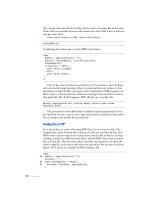
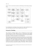
MSC bug_exh3
Removed beginning (47 messages)
DLC_7
waitUAdisc
/* Not yet consumed by */ dispatch_4
L_ReleaseReq
(1)
L_DataReq
( 1, 39 )
L_DataReq
V76frame
( DISC : (. 1 .))
V76frame
( DISC : (. 1 .))
L_ReleaseReq
(1)
DLC_7
process
<<Block DLCa>>
DLC
( 1, 39 )
Figure 7.23 Last steps of the error MSC trace
A. Exit from the Validator (answering No to the question).
B. In Windows (or Unix), make a copy of the file dlc.spr into dlc
v5.spr.
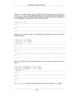
C. In process DLC,pagepart2, insert a coma followed by L
DataReq in the input containing
L
ReleaseReq previously added, as illustrated in Figure 7.24.
D. Save the SDL model.
waitUAdisc
V76frame (V76para)
V76para ! present
UA, DM
DLCstopped(me)
ELSE
-
L_ReleaseReq,
-
L_DataReq
Figure 7.24 After adding input of signal L DataReq
7.3.3.3 Run the exhaustive simulation
A. In the Organizer, select the SDL system V76test and press the Validate
button.
B. In the Validator, select Commands > Include Command Script, a nd choose sig
defs.com.
C. Press on List Signal, and check that you get the same signals as previously.
D. In the Validator, select Options2 > Exhaustive: Depth and enter 30.
202 Validation of Communications Systems with SDL
E. Press on Exhaustive; the Validator displays:
** Starting exhaustive exploration **
Search depth : 30
** Exhaustive exploration statistics **
No of reports: 3
Generated states: 8425
Truncated paths: 1708.
Unique system states: 6856.
Size of hash table: 100000 (400000 bytes)
Current depth: -1
Max depth: 30
Min state size: 212
Max state size: 572
Symbol coverage : 90.55
The exhaustive simulation has stopped and found 6856 unique system states (note that more
states would have been found if the search depth was not limited to 30). The Report Viewer
appears, showing that the only reports are three MaxQueueLength: the default limit of three
signals in some process input queues has been exceeded. This is normal; more details are
provided later.
In the 6856 explored global states of the SDL model, we are sure that we have no errors and
no deadlocks. However, the global states not yet explored by the Simulator may contain errors.
7.3.4 Millions of states: detect output to Null
Now to test more features in the SDL model, we use a larger model configuration: again, one
signal maximum in each queue, but the maximum exploration depth is no longer limited. To
limit the number of states, we restrict the number of retransmissions in process DLC to 1,
instead of 3.
7.3.4.1 Limit number of signals in input queue
To avoid an infinite number of global states, we need to limit the number of signals present in
the input queue of each SDL process.
For example, in the V.76 SDL model, if you simulate the scenario shown in Figure 7.51,
the queue of the instance 1 of process DLC in block DLCa contains 4 signals. If this process
does not input the signals in its queue while other bursts of L
DataReq are transmitted to
process dispatch, the number of L
DataReq stacked in the queue will grow rapidly. In addi-
tion, each new signal stacked in the queue generates a new global SDL model state during
exhaustive simulation.
The Validator by default limits to three signals in each process instance input queue. To
reduce the number of states, we will limit to one signal in each queue; note that some models
might not work with such a limit, for example, if two signals are transmitted at the same time
to a process queue.
Exhaustive Simulation 203
7.3.4.2 Modify the SDL model
A. Exit from the Validator (answering No to the question).
B. Open process DLC part1 and replace 3 by 1 in the declaration of N320, to obtain:
SYNONYM N320 Integer = 1;
C. Save the SDL model.
7.3.4.3 Run the bit-state simulation
After trying exhaustive simulation, we have found that it required 416 MB of RAM for 406049
unique global states of the SDL model. In ObjectGeode, we use exhaustive simulation because
it compresses the global states (for example, storing once several identical input queues): in
only 196 MB of RAM, ObjectGeode stores 2620001 states of the same model.
This is why instead of using exhaustive simulation we will use bit-state. Bit-state mode is
similar to exhaustive mode, but it requires less memory, because instead of storing each new
global model state, bit-state stores only one bit in an array. The index in the array is a hash-
coding (a kind of checksum) of the global state contents. However, two different global states
may have the same hash-code: they are considered as identical, therefore parts of the states
graph may remain unexplored.
A. In the Organizer, select the SDL system V76test and press Validate
.
B. In the Validator, select Options1 > Input Port Length,andenter1.
C. Select Options2 > Bit State: Hash Size and enter 250000000 (250 millions of bytes). This
is the size of the array of bits used to store the states hash-codes. If your machine is
equipped, for example, with 128 MB of RAM, enter 80 millions.
D. Select Options2 > Bit State: Depth and enter 15000.
E. Select Commands > Include Command Script, a nd choose sig
defs.com.
F. Press on List Signal, and check that you get the same signals as previously.
G. Press on Bit State, the Validator displays:
** Starting bit state exploration **
Search depth : 15000
Hash table size : 250000000 bytes
Transitions: 20000 States: 12408 Reports: 5 Depth: 376 Symbol
coverage: 93.60 Time: 10:07:07
Transitions: 40000 States: 24847 Reports: 5 Depth: 300 Symbol
coverage: 93.60 Time: 10:07:07
Transitions: 60000 States: 37274 Reports: 5 Depth: 138 Symbol
coverage: 93.60 Time: 10:07:07
204 Validation of Communications Systems with SDL
Transitions: 6940000 States: 4329979 Reports: 5 Depth: 215
Symbol coverage: 93.60 Time: 10:09:13
Transitions: 6960000 States: 4342489 Reports: 5 Depth: 92
Symbol coverage: 93.60 Time: 10:09:13
Transitions: 6980000 States: 4354917 Reports: 5 Depth: 172
Symbol coverage: 93.60 Time: 10:09:13
** Bit state exploration statistics **
No of reports: 5.
Generated states: 6985039.
Truncated paths: 0.
Unique system states: 4358006.
Size of hash table: 2000000000 (250000000 bytes)
No of bits set in hash table: 8675533
Collision risk: 0 %
Max depth: 6530
Current depth: -1
Min state size: 212
Max state size: 584
Symbol coverage : 93.60
After only 2 min and 6 s, the bit-state simulation is terminated. 4358006 unique global
states have been explored (you may get a different number), and the memory usage has
been almost constant and equal to 255 MB only: the bits array plus a few megabytes. As
the maximum depth indicated is equal to 6530, the search depth limit used, 15000, was
enough.
Because the hash table used could store up to 250 millions × 8 = 2 billions of bits, the
collision risk is evaluated at 0%.
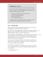
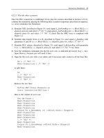
H. The Report Viewer appears. Double-click on the Output box to unfold it, as shown in
Figure 7.25.
I. The first box from the left shows that signal V76frame has been transmitted to a Null Pid
by process dispatch in block DLCa.
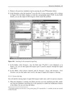
J. Double-click on this box: the MSC Editor displays the trace of the scenario leading to the
error; this trace is shown in Figure 7.26.
A attempts to establish DLC number 0; as the response L
EstabResp from B is too late,
A has received an L
ReleaseInd, meaning failure of DLC establishment; the L EstabResp
from B finally arrives (E1 in the MSC), dispatch in B creates an instance of DLC,which
transmits a v76frame containing a UA; reaching dispatch in A, the v76frame should have
been transmitted to the instance of DLC by executing transition TR1 in Figure 7.27; unfor-
tunately, the instance is dead; therefore, an output to a Null Pid is executed, detected by the
Validator.
Remark: the error discovered by ObjectGeode in the same configuration is a bit different.
The error scenario discovered by ObjectGeode cannot be replayed by the Validator, because
in ObjectGeode the feed command transmits signals to the model without storing them in the
input queues. When replaying the error discovered by ObjectGeode, the Tau Validator signals
Exhaustive Simulation 205
Figure 7.25 The Report Viewer (5 reports)
env_a env_b
DLC_6
process
<<Block DLCb>>
DLC
dispatch_4
process
<<Block DLCb>>
dispatch
dispatch_3
process
<<Block DLCa>>
dispatch
BtoA_2
BtoA
AtoB_1
AtoB
DLC_5
process
<<Block DLCa>>
DLC
MSC bug_exh4
L_ReleaseInd
DLCstopped
V76frame
(UA : (. 0 .))
V76frame
(UA : (. 0 .))
V76frame
(UA : (. 0 .))
(0, false)
L_EstabResp
V76frame
(SABME : (. 0 .))
T320(12)
T320(12)
L_EstabReq
( 0 )
L_EstabInd
( 0 )
V76frame
(SABME : (. 0 .))
(0, true)
V76frame
(SABME : (. 0 .))
( 0 )
( 0 )
E1
Figure 7.26 The error MSC trace
206 Validation of Communications Systems with SDL
PROCESS dispatch(1, 1)
ready
V76frame (V76para)
V76para ! present
SABME
DLCpeer:=
V76para ! SABME ! DLCi
DLCs(DLCpeer)
UA
V76frame(V76para)
TO DLCs(V76para !
UA ! DLCi)
-
etc.
output to
Null Pid
transition TR1
Figure 7.27 The output to Null in process dispatch part1 (extract)
that the input queue limit (of 1 signal here) is reached when transmitting the L EstabResp:the
input queue of dispatch already contains the saved v76frame.
7.3.4.4 Correct the error
The simulation has revealed that we must protect the expressions after TO in the output state-
ments to avoid having a Null Pid. For that, you will add a decision to test the value of the
expression: if Null, the output is not performed.
A. Exit from the Validator (answering No to the question).
B. In Windows (or Unix), make a copy of the file dispatch.spr into dispatch
v6.spr.
C. Open process dispatch in the SDL Editor, and create a new page part1 2 and rename
part1 part1
1.
D. Split the state machine in part1
1 into two parts, one in part1 1 and the other in part1 2,
as illustrated in Figures 7.28 and 7.29.
E. Insert four decisions in part1
1 as illustrated in Figure 7.28.
F. Insert one decision in part2 after the answer UA, as shown in Figure 7.30.
G. Save the SDL model.
7.3.5 Forty seconds to detect missing save of L
DataReq
7.3.5.1 Run again the bit-state simulation
To save time, we will set the Validator to stop after discovering two exceptions, rather than
finishing the whole reachable states exploration.
A. In the Organizer, select the SDL system V76test and press Validate
.
B. Select Options2 > Bit State: Depth and enter 15000.
Exhaustive Simulation 207
PROCESS dispatch(1, 1)
part1_1(3)
NEWTYPE DLCsArray
ARRAY(DLCident, PID)
ENDNEWTYPE;
DCL
/* to store the PIDs of instances
of process DLC, necessary in
outputs to route signals : */
DLCs DLCsArray;
/* Temporary variables: */
DCL
DLCnum, DLCpeer DLCident,
uData Integer,
V76para V76paramTyp;
ready
V76frame
(V76para)
ready
V76para ! present
DLCs(V76para !
I ! DLCi)
DLCs(V76para !
DISC ! DLCi)
L_SetparmInd L_SetparmConf
lab1
V76frame(V76para)
TO DLCs(V76para !
I ! DLCi)
V76frame(V76para)
TO DLCs(V76para !
DISC ! DLCi)
waitParmResp
-
DLCs(V76para !
UA ! DLCi)
DLCs(V76para !
DM ! DLCi)
L_SetparmResp V76frame
V76frame(V76para)
TO DLCs(V76para !
UA ! DLCi)
V76frame(V76para)
TO DLCs(V76para !
DM ! DLCi)
V76frame
(XIDresp : 0)
VIA dlcDL
- - ready
I DISC XIDcmd XIDresp
SABME
ELSEUA DM
ELSE
Null
ELSE
Null
ELSE
Null
ELSE
Null
Figure 7.28 Process dispatch page part1 1
PROCESS dispatch(1, 1) part1_2(3)
lab1
DLCpeer:=
V76para ! SABME ! DLCi
DLCs
(DLCpeer)
L_ReleaseInd
(DLCpeer)
L_EstabInd
(DLCpeer)
V76frame
(DM :(. DLCpeer .))
VIA dlcDL
waitEstabResp -
ELSE
Null
L_EstabResp V76frame
DLC
(DLCpeer, False)
Creates
instance of
process DLC
DLCs(DLCpeer)
:= OFFSPRING
Stores into the
table the PID of the
instance just created.
ready
waitEstabResp
Figure 7.29 Process dispatch page part1 2
208 Validation of Communications Systems with SDL
PROCESS dispatch(1, 1) part2(3)
ready
L_DataReq
(DLCnum, uData)
L_ReleaseReq
(DLCnum)
L_EstabReq
(DLCnum)
DLCs
(DLCnum)
DLCs
(DLCnum)
DLCs
(DLCnum)
DLCnum not
used, we create
an instance of
process DLC
L_DataReq
(DLCnum, uData)
TO DLCs(DLCnum)
L_ReleaseReq
(DLCnum) TO
DLCs(DLCnum)
DLC
(DLCnum, True)
L_ReleaseInd
(DLCnum)
Pass the frame to
the corresponding
instance of proc. DLC
-
DLCs(DLCnum)
:= OFFSPRING
We store into the
table the PID of
the new instance
-
- ready
waitUA
DLCstopped
(DLCnum)
L_SetparmReq
V76frame
(V76para)
DLCstopped
(DLCnum)
L_ReleaseInd
(DLCnum)
V76frame
(XIDcmd : 0)
VIA dlcDL
V76para ! present
L_ReleaseInd
(DLCnum)
DLCs(DLCnum)
:= NULL
DLCs(V76para !
UA ! DLCi)
DLCs(DLCnum)
:= Null
-
V76frame(V76para)
TO DLCs(V76para
! UA ! DLCi)
ready
ready
-
ELSE
Null
ELSE
Null
Null
ELSE
UA
ELSE
ELSE
Null
Figure 7.30 Process dispatch page part2
C. In the Validator, select Options1 > Input Port Length, and enter 2. We no longer limit
to 1 because in each process queue, we need enough space for a saved signal plus an
external signal.
D. Select Options1 > Report: Report Log, choose MaxQueueLength and select Off.TheVal-
idator will no longer generate any report when reaching the input port length limit.
E. Select Commands > Include Command Script, a nd choose sig
defs.com.
F. Press on List Signal, and check that you get the same signals as previously.
G. Press on Bit State, the Validator displays:
** Starting bit state exploration **
Search depth : 15000
Hash table size : 1000000 bytes
Exhaustive Simulation 209
Transitions: 20000 States: 12484 Reports: 0 Depth: 708
Symbol coverage: 89.02 Time: 15:53:12
Transitions: 40000 States: 24892 Reports: 0 Depth: 604
Symbol coverage: 96.44 Time: 15:53:12
Transitions: 1840000 States: 1136439 Reports: 2 Depth: 1783
Symbol coverage: 98.22 Time: 15:53:51
Transitions: 1860000 States: 1148820 Reports: 2 Depth: 2262
Symbol coverage: 98.22 Time: 15:53:51
Transitions: 1880000 States: 1160825 Reports: 2 Depth: 3279
Symbol coverage: 98.22 Time: 15:53:51
H. When you see in the trace that the number of reports is no longer null, press on Break:
*** Break at user input ***
** Bit state exploration statistics **
No of reports: 2.
Generated states: 1888000.
Truncated paths: 0.
Unique system states: 1165580.
Size of hash table: 8000000 (1000000 bytes)
No of bits set in hash table: 2062758
Collision risk: 25 %
Max depth: 3639
Current depth: 3623
Min state size: 212
Max state size: 628
Symbol coverage : 98.22
I. In the Report Viewer, double-click on the ImplSigCons box to unfold it, as shown in
Figure 7.31.
J. The first box from the left shows that signal L
DataReq has been discarded by process
DLC in block DLCa.
K. Double-click on this box: the MSC Editor displays the trace of the scenario leading to the
error; this trace is shown in Figure 7.32.
We see that the target instance of process DLC in block DLCa (named DLC
25 ) is in state
waitUA. If we look at the SDL model, under this state no input or save of signal L
DataReq
are specified. Thus, this signal has been discarded.
7.3.5.2 Correct the error
We decide to save signal L
DataReq in state waitUA, because once the connection is set up,
the signal can be processed.
A. Exit from the Validator (answering No to the question).
B. In Windows (or Unix), make a copy of the file dlc.spr into dlc
v7.spr.
210 Validation of Communications Systems with SDL
Figure 7.31 The Report Viewer (2 reports)
dispatch_4
process
<<Block DLCb>>
dispatch
dispatch_3
process
<<Block DLCa>>
dispatch
BtoA_2
BtoA
AtoB_1
AtoB
env_0
MSC bug_exh5
Removed beginning (784 messages)
DLC_25
waitUA
L_DataReq
( 0, 86 )
L_DataReq
DLC_25
process
<<Block DLCa>>
DLC
( 0, 86 )
Figure 7.32 The end of the error MSC trace
C. In process DLC,pagepart1, add below state waitUA a save symbol containing signal
L
DataReq, as shown in Figure 7.33.
D. Save the SDL model.
7.3.6 Two minutes to detect missing input L
ReleaseReq and answer DM
This time we will limit the input port length to 1 instead of 2, to finish more rapidly the bit-state
simulation, to show how to detect never-executed SDL symbols.
Exhaustive Simulation 211
waitUA
V76frame (V76para)
V76para ! present
T320
N320cnt < N320
L_DataReq
Figure 7.33 Process DLC after adding save L DataReq under waitUA
7.3.6.1 Run again the bit-state simulation
A. In the Organizer, select the SDL system V76test and press Validate
.
B. In the Validator, select Options1 > Input Port Length,andenter1.
C. Select Options2 > Bit State: Hash Size and enter 250000000 (250 millions of bytes). If
your machine is equipped, for example, with 128 MB of RAM, enter 80 millions.
D. Select Options2 > Bit State: Depth and enter 15000.
E. Select Options1 > Report: Report Log, choose MaxQueueLength and select Off.
F. Select Commands > Include Command Script, and choose sig
defs.com.
G. Press on List Signal, and check that you get the same signals as previously.
H. Press on Bit State, the Validator displays:
** Starting bit state exploration **
Search depth : 15000
Hash table size : 250000000 bytes
Transitions: 20000 States: 12408 Reports: 0 Depth: 376
Symbol coverage: 93.77 Time: 20:06:38
Transitions: 40000 States: 24847 Reports: 0 Depth: 300
Symbol coverage: 93.77 Time: 20:06:38
Transitions: 7180000 States: 4479778 Reports: 0 Depth: 65
Symbol coverage: 93.77 Time: 20:08:43
Transitions: 7200000 States: 4492191 Reports: 0 Depth: 150
Symbol coverage: 93.77 Time: 20:08:43
** Bit state exploration statistics **
No of reports: 0.
Generated states: 7204384.
Truncated paths: 0.
Unique system states: 4494891.
Size of hash table: 2000000000 (250000000 bytes)
212 Validation of Communications Systems with SDL
No of bits set in hash table: 8948021
Collision risk: 0 %
Max depth: 6530
Current depth: -1
Min state size: 212
Max state size: 584
Symbol coverage : 93.77
This time, no exception has been found, and the bit-state simulation has explored all the states
of the SDL model reachable in the current test configuration (input ports limited to 1 etc.).
7.3.6.2 Analyze the nonexecuted SDL statements
After performing bit-state simulation, we must inspect the parts of the SDL model never exe-
cuted. We see in the results displayed:
Symbol coverage : 93.77
Lets see exactly where the 6.23% never-executed symbols are.
A. In the Validator, select Commands > Show Coverage Viewer. The coverage viewer window
appears as in Figure 7.34. If you double-click on the symbols marked with a zero, the SDL
Editor opens the corresponding diagram and selects the symbol.
The two uncovered symbols under process dispatch correspond to the reception of a
v76frame containing a DM.
The four symbols under process DLC correspond to two ELSE answers, supposed to never
occur, and to the reception of a v76frame containing a DM under state waitUA shown in
Figure 7.35.
These two uncovered receptions of v76frame containing a DM cannot happen in our sim-
ulation, because signal L
ReleaseReq is never transmitted to side B (because the channel
dis has been disabled in file sig
defs.com), but only to side A. Therefore, a connection
established by A cannot be refused by B: the scenario shown in Figure 7.36 cannot happen.
The MSC in Figure 7.36 shows the parts missing in the SDL model to refuse a connection:
first, in process dispatch under state waitEstabResp the input of L
ReleaseReq is missing:
Figure 7.37 shows this input added, followed by the transmission of DM. Second, when DM
is received in dispatch, the answer DM is missing: Figure 7.38 shows this answer added,
passing the DM to process DLC.
Now, as process DLC can receive DM, the symbols shown in Figure 7.34 should be covered
by the simulation.
B. Exit from the Validator (answering No to the question).
C. In Windows (or Unix), make a copy of the file dispatch.spr into dispatch
v8.spr.
D. Add the missing parts in process dispatch, as depicted in Figures 7.37 and 7.38.
E. Save the SDL model.
Exhaustive Simulation 213
Figure 7.34 The six uncovered symbols in the coverage viewer
PROCESS DLC (0, maxDLC + 1) FPAR me DLCident, originator Boolean
waitUA
V76frame (V76para)
V76para ! present
UA
RESET (T320)
L_EstabConf
(me)
connected
DM
DLCstopped
(me)
ELSE
-
never executed
Figure 7.35 The branch never executed in process DLC
214 Validation of Communications Systems with SDL
AtoB_1
MSC cnx_refused
l_estabreq( 0 )
v76frame( dm : (. 0 .) )
v76frame( dm : (. 0 .) )
dlcstopped( 0 )
l_releaseind( 0 )
v76frame( sabme : (. 0 .) )
v76frame( sabme : (. 0 .) )
v76frame( dm : (. 0 .) )
l_estabind( 0 )
l
_releasereq( 0 )
<<Block DLCa>>
dispatch
dispatch_3
waitUA
DLC_7
t320(12.0 )
waitUA
AtoB BtoA
BtoA_2
<<Block DLCb>>
dispatch
dispatch_4
waitEstabResp
DM reception
not covered
DM
answer
missing
L_ReleaseReq
input missing
env_a env_b
<<Block DLCa>>
DLC
Figure 7.36 MSC showing connection establishment from A refused by B
PROCESS dispatch(1, 1) part1_2(3)
DLCpeer:=
V76para ! SABME ! DLCi
DLCs
(DLCpeer)
L_ReleaseInd
(DLCpeer)
L_EstabInd
(DLCpeer)
V76frame
(DM :(. DLCpeer .))
VIA dlcDL
L_EstabResp V76frame
DLC
(DLCpeer, False)
Creates
instance of
process DLC
DLCs(DLCpeer)
:= OFFSPRING
Stores into the
table the PID of the
instance just created.
ready
ELSE
Null
V76frame
(DM :(. DLCpeer .))
VIA dlcDL
DLCnum =
DLCpeer
True
False
L_ReleaseReq
(DLCnum)
ready
waitEstabResp
-
lab1
waitEstabResp
Figure 7.37 The input L ReleaseReq addedtoprocessdispatch
7.3.7 Three minutes, 6.7 million states, no error
7.3.7.1 Run again the bit-state simulation
We simply rerun the bit-state simulation to check that no error has been introduced, and see if
all the symbols are covered.
Exhaustive Simulation 215
waitUA
V76frame
(V76para)
DLCstopped
(DLCnum)
V76para ! present
L_ReleaseInd
(DLCnum)
DLCs(V76para !
DM ! DLCi)
DLCs(V76para !
UA ! DLCi)
DLCs(DLCnum)
:= Null
V76frame(V76para)
TO DLCs(V76para
! DM ! DLCi)
V76frame(V76para)
TO DLCs(V76para
! UA ! DLCi)
ready
ready
-
DM
UA
ELSE
ELSE
Null
ELSE
Null
PROCESS dispatch(1, 1) part2(3)
Figure 7.38 The answer DM added to process dispatch
A. In the Organizer, select the SDL system V76test and press Validate .
B. In the Validator, select Options1 > Input Port Length,andenter2.
C. Select Options2 > Bit State: Hash Size and enter 250000000 (250 millions of bytes). If
your machine is equipped, for example, with 128 MB of RAM, enter 80 millions.
D. Select Options2 > Bit State: Depth and enter 400.
E. Select Options1 > Report: Report Log, choose MaxQueueLength and select Off.
F. Select Commands > Include Command Script, and choose sig
defs.com.
G. Press on List Signal, and check that you get the same signals as previously.
H. Enter the command Channel-Enable dis to enable the Validator to transmit signal
L
ReleaseReq to side B, to cover the SDL transitions previously added:
Command : Channel-Enable dis
Channel enabled.
I. Press on Bit State, the Validator displays:
** Starting bit state exploration **
Search depth : 400
Hash table size : 250000000 bytes
Transitions: 20000 States: 15362 Reports: 0 Depth: 393
Symbol coverage: 63.38 Time: 16:36:15
Transitions: 40000 States: 31214 Reports: 0 Depth: 398
Symbol coverage: 63.38 Time: 16:36:15
216 Validation of Communications Systems with SDL
Transitions: 10140000 States: 6736587 Reports: 0 Depth: 397
Symbol coverage: 98.31 Time: 16:39:19
Transitions: 10160000 States: 6750862 Reports: 0 Depth: 380
Symbol coverage: 98.31 Time: 16:39:19
J. After around six millions of states, press on Break; the Validator displays:
*** Break at user input ***
** Bit state exploration statistics **
No of reports: 0.
Generated states: 10168000.
Truncated paths: 794235.
Unique system states: 6756790.
Size of hash table: 2000000000 (250000000 bytes)
No of bits set in hash table: 13377019
Collision risk: 0 %
Max depth: 400
Current depth: 397
Min state size: 212
Max state size: 616
Symbol coverage : 98.31
No exception has been found. In 3 min and 4 s, the Validator has explored 6756790 of the
reachable states of the SDL model. As we have enabled the SDL channel dis, more external
signals are transmitted by the Validator to the SDL model than in the previous sessions: the
simulation has been stopped before its end, the depth of which has been limited to 400 tran-
sitions. There are many truncated paths; therefore, this depth could be increased in order to
explore all the states.
Remark: Tau generally finds more global states than ObjectGeode when the simulated SDL
model expects signals coming from the environment, because in Tau Validator such signals
are stored into the input queues of the process instances (like the other signals), whereas in
ObjectGeode Simulator, such signals are input directly (like in a rendezvous).
7.3.7.2 Analyze the nonexecuted SDL statements
We must inspect again the parts of the SDL model that were never executed. We see in the
results displayed:
Symbol coverage : 98.31
Lets see exactly where the 1.69% never-executed symbols are.
A. In the Validator, select Commands > Show Coverage Viewer. The coverage viewer window
appears, as in Figure 7.39. Only one SDL symbol remains uncovered: it is an ELSE answer
Exhaustive Simulation 217
Figure 7.39 The symbol not covered in the coverage viewer
supposed to never occur. Therefore, this simulation session has covered all the symbols of
the SDL model.
In a few minutes of simulation, you have:
• corrected all the discovered exceptions,
• covered all the SDL symbols, and
• proved that the SDL model contains no deadlock.
Note that this concerns a reduced model configuration. Bear in mind that millions of different
scenarios have been executed here.
The next steps could be to simulate with other external signals configurations and other
Validator settings such as different scheduling (default is First) or different priorities (default
is higher priority to internal events than to signals from ENV).
7.3.8 Bit-state simulation with a user-defined rule
We want to detect that in our V.76 SDL model:
• instance 1 of process AtoB is in state ready,
• and instance 1 of process BtoA is in state ready.
218 Validation of Communications Systems with SDL
More details on user-defined rules are provided in Chapter 5.
A. In the Organizer, select the SDL system V76test and press the Validate
button.
B. In the Validator command line, enter:
Define-Rule state(AtoB:1)=ready and state(BtoA:1)=ready
C. Select Options1 > Report : Abort, and choose UserSpecified. After one report, the simula-
tion will stop.
D. Press on Bit State, the Validator displays:
Search depth : 100
Hash table size : 1000000 bytes
** Bit state exploration statistics **
No of reports: 1.
Generated states: 3.
Truncated paths: 0.
Unique system states: 2.
Size of hash table: 8000000 (1000000 bytes)
etc.
The simulation is terminated because the Validator has encountered a global state where the
rule is true. The Report Viewer appears, as in Figure 7.40, showing that the rule is satisfied.
To view the corresponding MSC trace, double-click on the lower box in the Report Viewer.
Figure 7.40 The Report Viewer showing that the rule is satisfied
7.3.9 Verifying an MSC with bit-state simulation
You will simulate the V.76 SDL model, observed by the basic MSC test1.msc. The Validator
also accepts MSCs containing in-line operators and High-Level MSCs (HMSC).
Check that in test1.msc there is either a single environment instance named env
0 or two
environment instances named DLCaSU and DLCbSU (the names of the two external channels
in the SDL model), otherwise the simulation would not match the loaded MSC.
Exhaustive Simulation 219
More details on verifying an MSC are provided in Chapter 5.
A. In the Organizer, select the SDL system V76test and press the Validate
button.
B. In the Validator, press on Verify MSC, and select the MSC test1.msc. The Validator starts a
bit-state exploration:
MSC Test1 loaded.
Root of behavior tree set to current system state
Reports cleared
Bit state exploration started.
After less than one second, the Validator has finished:
** Bit state exploration statistics **
No of reports: 4.
Generated states: 69.
Truncated paths: 0.
Unique system states: 62.
Size of hash table: 8000000 (1000000 bytes)
No of bits set in hash table: 124
Symbol coverage : 78.03
** MSC Test1 verified **
The Report Viewer appears, as in Figure 7.41, showing four reports. There is one scenario
satisfying the MSC and two scenarios violating the MSC. There are two violations because
the MSC test1 does not contain any possible behavior expected from the system. To view the
corresponding MSC trace, double-click on one box in the Report Viewer.
Figure 7.41 The Report Viewer showing that the MSC is satisfied
The textual command Define-MSC-Verification-Algorithm can be used to change the algo-
rithm used by the Verify MSC command. The default is BitState, the other alternative is
TreeSearch.
220 Validation of Communications Systems with SDL
7.3.10 Bit-state simulation with observer processes
You will use the observer process created in Chapter 5, shown in Figure 5.36. This observer
detects if the variable uData in process dispatch in block DLCa contains 55 .
A. In the Organizer, select V76test, choose Edit > Connect, choose To an existing file,press
the folder-shaped icon and connect to the file v76test
obs.ssy.
B. In the Organizer, select obs, choose Edit > Connect, choose To an existing file,pressthe
folder-shaped icon, select the file obs.sbk, check Expand substructure and press Connect.
C. In the Organizer, press the save button.
The Organizer should now look like Figure 7.42.
Figure 7.42 The Organizer showing the observer obs
D. In the Organizer, select the SDL system V76test and press the Validate button.
E. In the Validator, enter the command:
define-observer obs1
This command tells the Validator to execute obs1 as an observer instead of a regular process.
F. Select Options1 > Report : Abort, and choose Assertion. After one observer report, the
simulation will stop.
G. Press on Bit State, the Validator displays:
Search depth : 100
Hash table size : 1000000 bytes
Exhaustive Simulation 221
** Bit state exploration statistics **
No of reports: 2.
Generated states: 195.
Truncated paths: 0.
Unique system states: 147.
Size of hash table: 8000000 (1000000 bytes)
etc.
The simulation is terminated because the Validator has encountered a global state where the
observer process obs1 has called the procedure Report. The Report Viewer appears, as illustrated
in Figure 7.43, showing two reports. To view the corresponding MSC trace, double-click on
the lower box in the Report Viewer.
Figure 7.43 The Report Viewer showing that the assertion is reached
7.4 CASE STUDY WITH OBJECTGEODE
You will run the exhaustive simulation on the V.76 SDL model to discover errors auto-
matically, and much faster and with much better dynamic coverage than with interactive or
random simulation.
7.4.1 One second to detect missing save of v76frame
7.4.1.1 Start the Simulator
A. Open the model contained in v76.pr with the SDL Editor. Be sure to use the last version
of v76.pr, including the two corrections mentioned in the previous chapters:
• Input signal DLCstopped added under state waitUA in process dispatch.
• Process dispatch goes to state ready instead of state waitUA after transmitting L
Release-
Ind.
B. With a text editor, open the file v76.startup and remove the comment delimiter
before the
line source v76
feed.wri, preventing the feed commands execution, mentioned in Chapter 6.
222 Validation of Communications Systems with SDL
C. Select Tools > SDL & MSC Simulator.
D. In the ObjectGeode Launcher, remove any file other than v76.pr,presstheBuild button,
then, if there are no errors, press the Execute button. The Simulator starts.
E. If the Simulator has not executed automatically the four start transitions (step should be
equal to 4), the file v76.startup is missing or incorrect (see Chapter 4). The exhaustive
simulation starts from the current SDL model state, here Step 4.
F. Check that the feed commands (loaded by the file v76.startup) have been executed. See
Chapter 4 if typing the Simulator command list feed does not give the following result:
> list feed
feed dlcbsu l_releasereq(0)
feed dlcbsu l_setparmresp()
feed dlcbsu l_estabresp()
feed dlcasu l_datareq(1 , 39)
feed dlcasu l_datareq(0 , 86)
feed dlcasu l_releasereq(1)
feed dlcasu l_setparmreq()
feed dlcasu l_estabreq(1)
feed dlcasu l_estabreq(0)
7.4.1.2 Run the exhaustive simulation
A. In the Simulator, select Execute > Verify:theVerify Options window appears, as shown in
Figure 7.44. Do NOT use the Simulator button Verify
B. In the Exploration part, enter 20000 for States Limit (you could also type the equivalent
Simulator textual command define states
limit 20000 ).
C. Press the button Verify and confirm the verification startup: the Simulator displays the current
options and starts the exhaustive simulation:
mode breadth
define edges_dump ’’
define states_dump ’’
deadlock limit 2
exception limit 2
stop limit 2
define stop_cut true
define states_limit 20000
define depth_limit 0
define verify_stats true
As expected, the exhaustive simulation stops after the exploration of 20000 global SDL
model states. Only one second has been necessary to discover 568 exceptions, as indicated in
the results:
(8192 states 19364 trans. 0 sec, depth=13, breadth=1897)
(16384 states 39243 trans. 1 sec, depth=15, breadth=3873)
verify stopped by states limit
Exhaustive Simulation 223
Figure 7.44 The Verify Options window
Number of states : 20000
Number of transitions : 47926
Maximum depth reached : 16
Maximum breadth reached : 6009
duration : 0 mn 1 s
Number of exceptions : 568
Number of deadlocks : 0
Number of stop conditions : 0
etc.
We see that the Simulator has executed 47 926 SDL transitions.
7.4.1.3 Replay the exception scenario
During the exhaustive simulation, as soon as the Simulator discovers a problem, it stores a
scenario into a file. This scenario is the sequence of transitions that are to be executed to go
from the initial state of the SDL model to the state where the problem has been discovered.
Here, the Simulator has generated two scenario files: v76.x1.scn and v76.x2.scn. The letter x
stands for exception. The number after x is the order in which the exception was found. To get
more files, you could enter a higher value for Exception Limit in the Verify Options window.
224 Validation of Communications Systems with SDL
However, it is generally simpler to fix the first error, to recompile the SDL model and start a
new simulation.
A. In the Simulator, press the button Start MSC.
B. Select File > Scenario > Load, and open v76.x1.scn.
C. Press the button Redo: All. The Simulator replays the scenario, reaches the exception,
and displays:
Unexpected signal v76frame in dlcb!dispatch, line 312
of v76.pr
11 transitions executed
end of scenario execution
The Editor displays the MSC trace of the exception scenario, shown in Figure 7.45.
bug_exh1
l_setparmreq
v76frame( xidcmd : 0 )
v76frame( xidcmd : 0 )
l_setparmreq
v76frame( xidcmd : 0 )
v76frame( xidcmd : 0 )
l_setparmind
inst_1_dlca.dispatch
PROCESS /
v76test/
dlca/dispatch(1)
inst_1_atob
PROCESS /
v76test/
datalink/atob(1)
inst_1_dlcb.dispatch
PROCESS /
v76test/
dlcb/dispatch(1)
Figure 7.45 MSC trace of the first exception scenario
D. Enter the command print state; the Simulator answers:
> print state
btoa(1) ! state = ready
atob(1) ! state = ready
dlcb!dispatch ! state = waitparmresp
dlca!dispatch ! state = ready
We see that process dispatch in block DLCb is in state waitParmResp. If we look at the SDL
model, under this state no input or save of signal v76frame are specified. Thus, this signal has
been discarded.
7.4.1.4 Correct the exception
To prevent the signal from being lost, you will add a save of signal v76frame in state wait-
ParmResp of process dispatch.
A. Exit from the Simulator (answering No to the question). Do not exit from the Editor.
B. In Windows (or Unix), make a copy of the file v76.pr into v76
v3.pr.
Exhaustive Simulation 225
waitParmResp
L_SetparmResp
V76frame
(XIDresp : 0)
VIA dlcDL
ready
V76frame
Figure 7.46 Missing save of signal v76frame added
C. In process dispatch, partition part1, select the input L SetParmResp under the state wait-
ParmResp, and add a save containing v76frame, as illustrated in Figure 7.46.
D. Save the SDL model.
7.4.1.5 Simulate to check the bug correction
To check that the bug has been corrected, you will load and automatically replay the scenario
v76.x1.scn.
A. In the SDL Editor, unload all files except v76.pr.
B. If the ObjectGeode Launcher is not running, in the Editor select Tools > SDL & MSC Sim-
ulator.
C. In the ObjectGeode Launcher, remove any file other than v76.pr,presstheBuild button,
then, if there are no errors, press the Execute button.
D. The Simulator starts: press on Start MSC.
E. In the Simulator, select File > Scenario > Load, open v76.x1.scn, and press the button Redo:
All. The Simulator replays the scenario and the exception no longer exists.
Do not exit from the Simulator.
7.4.2 One second to detect missing input L
ReleaseReq
7.4.2.1 Run the exhaustive simulation
A. In the Simulator, press on init
, then press on redo four times.
B. Select Execute > Verify: enter 20000 for States Limit,pressVerify and confirm the verifica-
tion startup.
This time, the exhaustive simulation has discovered 77 exceptions instead of 568, as indicated
in the results:
(8192 states 19777 trans. 0 seconds, depth=13, breadth=1925)
(16384 states 40292 trans. 1 seconds, depth=15, breadth=3944)
verify stopped by states limit
Number of states : 20000
Number of transitions : 49140