Enhanced Radio Access Technologies for Next Generation Mobile Communication phần 5 ppt
Bạn đang xem bản rút gọn của tài liệu. Xem và tải ngay bản đầy đủ của tài liệu tại đây (682.05 KB, 28 trang )
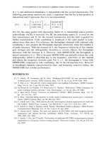
FUNDAMENTALS OF SINGLE-CARRIER CDMA TECHNOLOGIES 117
R =
3
/
4
and additional redundancy is transmitted with the second transmission. The
following puncturing matrices are used (1 represents that the bit at that position is
transmitted and 0 represents that it is not transmitted):
(51) P
1
=
⎡
⎣
111111
100000
000100
⎤
⎦
, P
2
=
⎡
⎣
000000
011110
110011
⎤
⎦
For CC, the same packet with puncturing matrix P
1
is transmitted until a positive
acknowledge (ACK) is received. For IR, the puncturing matrix P
1
is used for the
first transmission and P
2
for the second transmission and the order repeated for
further transmissions. Code combining is employed if the same packet is trans-
mitted more than once. For reference, the throughput obtained with coherent rake
combining is also plotted; the throughput degrades drastically when the number L
of paths increases. With the increase in L, the frequency-selectivity of the channel
gets stronger and the orthogonality distortion is severer. Hence, the throughput
decreases with the increase in L. However, with MMSE-FDE, the throughput is
almost insensitive to L. This is because MMSE-FDE can partially restore the code
orthogonality which is distorted due to the frequency selectivity of the channel
and obtain the frequency diversity gain. For L = 1, the throughput is lower with
MMSE-FDE compared to rake combining, due to the GI insertion loss. However
in broadband channels characterized by time- and frequency-selective fading, the
MMSE-FDE has a better performance.
REFERENCES
[1] F. Adachi, M. Sawahashi, and H. Suda, “Wideband DS-CDMA for next generation mobile
communications systems,” IEEE Commun. Mag., Vol. 36, No. 9, pp. 56–69, Sept. 1998.
[2] Y. Kim, et al., “Beyond 3G: vision, requirements, and enabling technologies,” IEEE Commun.
Mag., Vol. 41, No. 3, pp.120–124, Mar. 2003.
[3] M. Helard, R. Le Gouable, J-F. Helard and J-Y. Baudais, “Multicarrier CDMA techniques for
future wideband wireless networks,” Ann. Telecommun., vol. 56, pp. 260–274, 2001.
[4] S. Hara and R. Prasad, “Overview of multicarrier CDMA,” IEEE Commun. Mag., Vol. 35,
pp. 126–144, Dec. 1997.
[5] B. Sklar, “Rayleigh fading channels in mobile digital communication systems part 1: characteri-
zation,” IEEE Commun. Mag., pp. 90–100, July 1997.
[6] F. Adachi and T. Sao, “Joint antenna diversity and frequency-domain equalization for multi-rate
MC-CDMA,” IEICE Trans. Commun., Vol. E86-B, No. 11, pp. 3217–3224, Nov. 2003.
[7] F. Adachi, D. Garg, S. Takaoka, and K. Takeda, “Broadband CDMA techniques,” IEEE Wireless
Communications Magazine, Vol. 12, No. 2, pp. 8–18, Apr. 2005.
[8] F. Adachi and K. Takeda, “Bit error rate analysis of DS-CDMA with joint frequency-domain
equalization and antenna diversity combining,” IEICE Trans. Commun., Vol. E87-B, pp.
2991–3002, Oct. 2004.
[9] F. Adachi, T. Sao, and T. Itagaki, “Performance of multicode DS-CDMA using frequency domain
equalization in a frequency selective fading channel,” Electronics Letters, Vol. 39, pp. 239–241,
Jan. 2003.
118 CHAPTER 3
[10] D. Falconer, S. L. Ariyavistakul, A. Benyamin-Seeyar, and B. Eidson, “Frequency domain equal-
ization for single-carrier broadband wireless systems,” IEEE Commun. Mag., Vol. 40, pp. 58–66,
Apr. 2002.
[11] N. Benvenuto and S. Tomasin, “On the comparison between OFDM and single carrier modulation
with a DFE using a frequency-domain feedforward filter,” IEEE Trans. Commun., Vol. 50, No.
6, pp. 947–955, June 2002.
[12] A. M. Chan and G. W. Wornell, “A class of block-iterative equalizers for intersymbol interference
channels: fixed channel results,” IEEE Trans. Commun., Vol. 49, No. 11, pp. 1966–1976, Nov.
2001.
[13] N. Benvenuto and S. Tomasin, “Block iterative DFE for single carrier modulation,” IEE
Electronics Letters, Vol. 38, No. 19, pp. 1144–1145, Sept. 2002.
[14] S. Tomasin and N. Benvenuto, “A reduced complexity block iterative DFE for dispersive wireless
applications,” Proc. 60th IEEE Veh. Technol. Conf. 2004 Fall, Los Angels, U.S.A., 26–29 Sept.
2004.
[15] K. Takeda, K. Ishihara, and F. Adachi, “Downlink DS-CDMA transmission with joint MMSE
equalization and ICI cancellation,” Proc. 63rd IEEE Veh. Technol. Conf. 2006-Spring, Melbourne,
Australia, 7–10 May 2006.
[16] R. T. Derryberry, S. D. Gray, D. M. Ionescu, G. Mandyam, and B. Raghothaman, “Transmit
diversity in 3G CDMA systems,” IEEE Commun. Mag., Vol. 40, pp. 68–75, Apr. 2002.
[17] S. Alamouti, “A simple transmit diversity technique for wireless communications”, IEEE Journal
on Selected Areas in Commun., Vol. 16, No. 8, pp. 1451–1458, Oct. 1998.
[18] E. G. Larsson and P. Stoica, Space–time block coding for wireless communications, Cambridge
Univ. Press, Cambridge, UK, 2003.
[19] D. Garg and F. Adachi, “Performance improvement with space-time transmit diversity using
minimum mean square error combining equalization in MC-CDMA,” IEICE Trans. Commun.,
pp. 849–857, Mar. 2004.
[20] N. Al-Dhahir, “Single-carrier frequency-domain equalization for space-time block-coded transmis-
sions over frequency-selective fading channels,” IEEE Commun., Lett., Vol. 5, No. 7, pp. 304–306,
July 2001.
[21] F. W. Vook, T. A. Thomas, and K. L. Baum, “Cyclic-prefix CDMA with antenna diversity,”
Proc. 55th IEEE Veh. Technol. Conf. 2002-Spring, pp. 1002–1006, May 2002.
[22] K. Takeda, T. Itagaki, and F. Adachi, “Application of space-time transmit diversity to single-carrier
transmission with frequency-domain equalization and receive antenna diversity in a frequency-
selective fading channel,” IEE Proceedings Communications, Vol. 151, No. 6, pp. 627–632, Dec.
2004.
[23] W. Su, X. G. Xia, and K. J. R. Liu, “A systematic design of high-rate complex orthogonal
space-time block codes,” IEEE Commun. Lett., Vol. 8, No. 6, pp. 380–382, June 2004.
[24] F. Adachi, “Wireless past and future-evolving mobile communications systems,” IEICE Trans.
Fundamentals, Vol.E84-A, pp.55–60, Jan. 2001.
[25] G. J. Foschini and M. J. Gans, “On limits of wireless communications in a fading environment
when using multiple antennas”, Wireless Personal Communications, Kluwer, Vol. 6, No. 3, pp.
311–335, 1998.
[26] G. J. Foschini, “Layered space-time architecture for wireless communication in a fading
environment when using multi-element antennas,” Bell Lab. Tech. Journal, Vol. 1, No. 2, pp.
41–59, 1996.
[27] T. Matsumoto, J. Ylitalo, and M. Juntti, “Overview and recent challenges of MIMO system,”
IEEE Vehicular Technology Society News, pp. 4–9, May 2003.
[28] J. G. Proakis, Digital Communications, 4th edition, McGraw-Hill, 2001.
FUNDAMENTALS OF SINGLE-CARRIER CDMA TECHNOLOGIES 119
[29] P. W. Wolniansky, G. J. Foschini, G. D. Golden, and R. A. Valenzuela, “V-BLAST: an architecture
for realizing very high data rates over the rich-scattering wireless channel,” Proc. ISSSE, pp.
295–300, 1998.
[30] W. C., Jakes Jr., Ed., Microwave mobile communications, Wiley, New York, 1974.
[31] A. Nakajima, D. Garg, and F. Adachi, “Frequency-domain Iterative Parallel Interference Cancel-
lation for Multicode DS-CDMA-MIMO Multiplexing,” Proc. IEEE 62nd Veh. Technol. Conf.,
Dallas, U.S.A., 26–28 Sept. 2005.
[32] S. Haykin, Adaptive filter theory, 4th edition, Prentice Hall, 2001.
[33] Z. Wang and G. B. Giannakis, “Block precoding for MUI/ISI-resilient generalized multicarrier
CDMA with multirate capabilities,” IEEE Trans. Commun., Vol. 49, No. 11, pp. 2016–2027,
Nov. 2001.
[34] S. Tsumura, S. Hara, and Y. Hara, “Performance comparison of MC-CDMA and cyclically
prefixed DS-CDMA in an uplink channel,” Proc. IEEE VTC’04 Fall, Los Angeles, USA, pp.
414–418, Sept. 2004.
[35] X. D. Wang and H. V. Poor, “Iterative (turbo) soft interference cancellation and decoding for
coded CDMA,” IEEE Trans. Commun., Vol. 47, No. 7, pp. 1046–1061, July 1999.
[36] S. Zhou, G. B. Giannakis, and C. L. Martret, “Chip-interleaved block-spread code division
multiple access,” IEEE Trans. Commun., Vol. 50, No. 2, Feb. 2002.
[37] X. Peng, F. Chin, T. T. Tjhung, and A. S. Madhukumar, “A simplified transceiver structure for
cyclic extended CDMA system with frequency domain equalization,” Proc. IEEE VTC’05 Spring,
Sweden, pp. 1565–1569, May 2005.
[38] T. Ottosson and A. Svensson, “On schemes for multirate support in DS/CDMA,” J. Wireless
Personal Commun., Vol.6, No. 3, pp. 265–287, Mar. 1998.
[39] F. Adachi, M. Sawahashi, and K. Okawa, “Tree-structured generation of orthogonal spreading
code with different lengths for foward link of DS-CDMA mobile radio,” IEE Electron. Lett., Vol.
33, No. 1, pp. 27–28, Jan. 1997.
[40] L. Liu and F. Adachi, “2-dimensional OVSF spreading for chip-interleaved DS-CDMA uplink
transmission,” Proc. WPMC’05, Aalborg, Denmark, 19–22 Sept. 2005.
[41] L. Liu and F. Adachi, “2-dimensional OVSF Spread/Chip-interleaved CDMA,” IEICE Trans.
Commun., conditioned accepted.
[42] R. H. Morelos-Zaragoza, The art of error correcting codes, Wiley, 2002.
[43] S. Lin and D. J. Costello, Error Control Coding: Fundamentals and Applications, Prentice Hall,
Inc., 1983.
[44] D. Chase, “Code combining- A maximum likelihood decoding approach for combing and arbitrary
number of noisy packets,” IEEE Trans. Commun., Vol. COM-33, No. 5, pp. 385–393, May 1985.
[45] J. Hagenauer, “Rate-compatible punctured convolutional codes (RCPC codes) and their appli-
cation,” IEEE Trans. Commun., Vol. 36, No. 4, pp. 389–400, April 1988.
[46] D. N. Rowitch and L. B. Milstein, “Rate compatible punctured turbo (RCPT) codes in hybrid
FEC/ARQ system,” Proc. Comm. Theory Mini-conference, IEEE GLOBECOM’97, pp. 55–59,
Nov. 1997.
[47] T. Ji and W. E. Stark, “Turbo-coded ARQ schemes for DS-CDMA data networks over fading and
shadowing channels: throughput, delay and energy efficiency,” IEEE Journal on Selected Areas
in Commun., Vol. 18, No. 8, pp. 1355–1364, Aug. 2000.
[48] D. Garg and F. Adachi, “DS-CDMA with frequency-domain equalization for high speed downlink
packet access,” Journal on Selected Areas in Communications, Vol. 24, No. 1, pp. 161–170, Jan.
2006.
[49] D. Garg and F. Adachi, “Throughput comparison of turbo-coded HARQ in OFDM, MC-CDMA
and DS-CDMA with frequency-domain equalization,” IEICE Trans. on Commun., Vol. E88-B,
No.2, pp. 664–677, Feb. 2005.
120 CHAPTER 3
[50] C. Berrou, A. Glavieux, and P. Thitimajshima, “Near Shannon limit wrror-correcting coding and
ecoding:Turbo codes,” Proc. IEEE ICC, pp. 1064–1070, Geneva, May 1993.
[51] C. Berrou, “The ten-year-old turbo codes are entering into service,” IEEE Commun. Mag., Vol.
41, No. 8, pp. 110–116, Aug. 2003.
[52] J. P. Woodard and L. Hanzo, “Comparative study of turbo decoding techniques: an overview,”
IEEE Trans. Veh. Technol., Vol. 49, No. 6, pp. 2208–2233, Nov. 2000.
[53] D. Divsalar and F. Pollara, “Turbo codes for PCS applications,” Proc. IEEE ICC’95, pp. 54–59,
Seattle, Washington, June 1995.
[54] P. Robertson, E. Villebrum, and P. Hoeher, “A comparison of optimal and sub-optical MAP
decoding algorithms operating in the log domain,” Proc. IEEE ICC’95, pp. 1009–1013, Seattle
WA, June 1995.
[55] J. Hagenauer, E. Offer, and L. Papke, “Iterative decoding of binary block and convolutional
codes,” IEEE Trans. on Info. Theory, Vol. 42, No. 2, pp. 429–445, Mar. 1999.
[56] B. Sklar, “A primer on turbo code concepts,” IEEE Commun. Mag., Vol. 35, No.12, pp. 94–101,
Dec. 1997.
[57] C. Heegard and S. B. Wicker, Turbo coding, Kluwer Academic Publishers, 1999.
[58] L. R. Bahl, J. Cocke, F. Jelinek, and J. Raviv, “Optimal decoding of linear codes for minimizing
symbol error rate,” IEEE Trans. on Inf. Theory, pp. 284–287, March 1974.
[59] F. Adachi, K. Ohono, A. Higuchi, T. Dohi, and Y. Okumura, “Coherent multicode DS-CDMA
mobile radio,” IEICE Trans. Commun., Vol. E79-B, No. 9, pp. 1316–1325, Sept. 1996.
[60] A. Stefanov and T. Duman, “Turbo coded modulation for wireless communications with antenna
diversity,” Proc. IEEE VTC99-Fall, pp. 1565–1569, Netherlands, Sept. 1999.
CHAPTER 4
FUNDAMENTALS OF MULTI-CARRIER
CDMA TECHNOLOGIES
SHINSUKE HARA
Department of Information Systems, Graduate School of Engineering, Osaka City University, Japan
Abstract: This chapter introduces and compares two kinds of techniques based on combination
of CDMA and multicarrier transmission, such as Multicarrier CDMA and Multicarrier
DS/CDMA. Several detection and combining schemes are derived for both the techniques,
including a serial interference cancellation in uplink and a rake combining in downlink for
MC-DS/CDMA whereas a decorrelating multiuser detection and a minimum mean square
error (MMSE) multiuser detection in uplink and an orthogonality restoring combining
(ORC), an MMSE combining, a maximum ratio combining (MRC) and an equal gain
combining (EGC) in downlink for MC-CDMA. The bit error rate (BER) lower bounds for
the two techniques are theoretically analyzed and furthermore the BERs with the several
detection/combining schemes are demonstrated by computer simulations
Keywords: Multi-carrier transmission, MC-CDMA, MC-DS/CDMA, and maximu ratio combiner
1. INTRODUCTION
CDMA technique is robust to frequency-selective fading and it has been successfully
introduced in commercial cellular mobile communications systems such as IS-95
and 3G systems. On the other hand, multicarrier transmission technique is also
inherently robust to frequency-selective fading and in the name of orthogonal
frequency division multiplexing (OFDM), it has been also successfully introduced
in commercial wireless systems such as wireless local area networks (LANs) and
terrestrial digital video broadcasting (DVB-T). Therefore, it would be quite natural
to think of no synergistic effect in combination of these two techniques.
Whether the combination will be beneficial or not depends on a bandwidth
and a data transmission rate we intend to support. In fact, for a 2 Mbits/sec-
data transmission rate which 3G systems are now supporting, the combination of
CDMA and multicarrier transmission techniques brings no benefit at all. However,
if we intend to support much higher data transmission than this, such as in future
121
Y. Park and F. Adachi (eds.), Enhanced Radio Access Technologies for Next Generation Mobile
Communication, 121–150.
© 2007 Springer.
122 CHAPTER 4
4G systems, the combination does bring a benefit, in other words, it becomes a
promising data transmission technique.
This chapter introduces and compares two kinds of combination of CDMA
and multicarrier transmission techniques. One is Multicarrier (MC-) CDMA,
which was independently proposed by three different research groups in 1993,
and another is MC-DS/CDMA, which was also proposed in 1993 and then its
variant was proposed in 1996. The difference between the original and variant of
MC-DS/CDMA is that the former allows overlapping of subcarrier spectra whereas
the latter does not. The subcarrier non-overlapped MC-DS/CDMA is mathemat-
ically tractable, so in this chapter, we will use the (subcarrier non-overlapped)
MC-DS/CDMA.
This chapter is organized as follows. Section 2 shows a fatal problem of
DS/CDMA in high-speed data transmission and Section 3 introduces combination
of multicarrier transmission and CDMA as a solution of the problem. Section 4
explains several assumptions required forintroducing andcomparing MC-CDMAand
MC-DS/CDMA. After Section 5 outlines single-carrier DS/CDMA (In Chapter 3,
single-carrier CDMA is referred to as DS/CDMA. In this chapter, on the other hand,
to clearly show the structural difference between multi-carrier signaling and single-
carrier signaling, the single-carrier CDMA is called “single-carrier DS/CDMA.”),
MC-DS/CDMA is first introduced in Section 6 because MC-DS/CDMA has a
similaritytosingle-carrierDS/CDMA,andthenMC-CDMAisintroducedinSection7.
Section 8 demonstrates numerical results on the performance of MC-DS/CDMA and
MC-CDMA systems, and finally Section 9 concludes this chapter.
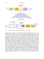
2. A FATAL PROBLEM OF DS/CDMA IN HIGH-SPEED DATA
TRANSMISSION
Let us assume that a signal is emitted at a DS/CDMA transmitter, it goes through
a frequency selective fading channel and then it arrives at a DS/CDMA receiver.
Figure 1 shows a block diagram of the DS/CDMA receiver with four rake finger
processors. At the receiver, a received signal is fed to a bandpass filter (BPF),
down-converted and then analog-to-digital (A/D) converted with I and Q branches.
At each rake finger processor, the A/D-converted baseband samples are despread
and integrated by a code generator and a correlator, and the differences in the
phases and arrival times among the correlator outputs are compensated for by
a phase rotator and a delay equalizer. Finally, a combiner sums up the channel
impairment-compensated symbols to recover user data symbols.
The matched filter output, namely, observation of a channel impulse response
is very important for DS/CDMA receiver, because it determines the number and
positions of the paths captured by the rake combiner to collect the energy of received
signal. When a receiver observes a channel, how finely it can analyze the temporal
structure of the channel is called “time resolution.” Defining the sampling rate as
R
smp
samples/sec, the time resolution t is given by 1/R
smp
sec, so the number of
resolvable paths in an observed impulse response of a channel is in proportion to
FUNDAMENTALS OF MULTI-CARRIER CDMA TECHNOLOGIES 123
A/D
Converter
Code
Generator
Delay
Equalizer
Channel
Estimator
Correlator
Down-
Converter
Phase
Rotator
BPF
I
Q
Rake Finger Processor 1
ΣI
ΣQ
t
Matched
Filter
Combiner
I
Q
Rake Finger Processor 2
Rake Finger Processor 3
Rake Finger Processor 4
Figure 1. A block diagram of a DS/CDMA rake receiver
the sampling rate. For DS/CDMA system, the sampling rate is determined by the
chip rate, so consequently, the number of resolvable paths is in proportion to the
chip rate.
Let us consider a case where we intend to support a data transmission rate of
up to 2 Mbits/sec in a wireless communication channel with carrier frequency of
f
c
. In this case, assuming spreading codes employed in 3G systems, a DS/CDMA
receiver always sees less than around ten paths in matched filter outputs of the
channel, as shown in Figure 2 (a). Therefore, the receiver can collect almost all part
of the received signal energy only with several rake finger processors. As shown
in Figure 1, roughly speaking, the hardware complexity of DS/CDMA receiver
is determined by the number of rake finger processors employed and this mild
number of rake finger processors was acceptable in terms of cost, size and power
consumption of 3G mobile terminals.
Now, let us consider a case where we intend to support a much higher data
transmission rate such as 100 Mbits/sec, which is a typical data transmission rate
discussed in 4G systems. This means that a DS/CDMA receiver will see several
t
(b) Matched filter output for the case of 100Mchips / sec
How many Rake finger processors
are required to effectively capture
the energy of received signal?
t
(a) Matched filter output for the case of 2Mchips / sec
Rake Finger
Processor 1
Rake Finger
Processor 2
Rake Finger
Processor 3
Rake Finger
Processor 4
Figure 2. Comparison of matched filter output
124 CHAPTER 4
hundreds of paths in impulse response of the channel, as shown in Figure 2 (b),
and hence it needs to have several hundreds of rake finger processors to effec-
tively collect the energy of received signal. This will be prohibitive (Note that,
using frequency domain equalizer instead of time domain rake combiner, the bit
error rate (BER) of DS/CDMA system can be drastically improved as shown in
Chapter 3).
3. COMBINATION OF MULTICARRIER TRANSMISSION
AND CDMA
Reducing the data transmission rate results in lessening the number of rake finger
processors, but it seems contradictory to achieving a high data transmission rate.
However, as shown in Figure 3, a high data transmission rate is achievable with
a number of lower data rate sub-channels with different carrier frequencies. This
is the very idea of multicarrier transmission, which is the principle of transmitting
data by dividing a data stream into a number of data streams, each of which has
a much lower data rate and by using these substreams to modulate subcarriers. In
Figure 3, the multicarrier system supports M parallel transmissions, reducing the
transmission rate over each sub-channel by factor of M.
Limiting our discussion within application of CDMA technique to high data rate
transmission, there are mainly two ways considered in combination of multicarrier
and CDMA techniques. One way is to employ a mild number of sub-channels
where there remains a frequency-selective fading in each sub-channel, and another
way is to employ a huge number of sub-channels where frequency-selective fading
has disappeared in each sub-channel. The former is called “multicarrier (MC)-
DS/CDMA,” which still requires a DS rake approach to effectively collect the
energy of received signal over each sub-channel, whereas the latter is called “multi-
carrier (MC)-CDMA,” which employs a spreading operation across the whole sub-
channels to gain frequency diversity effect. Figure 4 compares the power spectral
densities (PSDs) among a Single-carrier (SC)-DS/CDMA, MC-DS/CDMA and
MC-CDMA waveforms.
t
f
c
Multicarrierization
f
f
t
f
1
f
2
f
M
t
t
Figure 3. Multicarrierization
FUNDAMENTALS OF MULTI-CARRIER CDMA TECHNOLOGIES 125
f
f
c
BW
S
(a) PSD of An SC-DS/CDMA Waveform
f
f
c
+ f
m
BW
Dsub
(b) PSD of An MC-DS/CDMA Waveform
f
c
+ f
1
f
c
+ f
M
D
BW
D
f
J
M
2
1
f
c
BW
M
≅ (PJ
M
–1)/t
M
+ 2/T
M
T
M
P/t
M
Δ
f
= 1/t
M
Total PJ
M
Subcarriers
(c) PSD of An MC-CDMA Waveform
Figure 4. Power spectral densities
4. SYSTEM MODEL
4.1 Multiplexing/Multiple Access and Spreading Codes
It is assumed that SC-DS/CDMA, MC-DS/CDMA and MC-CDMA systems support
K multiplexing/multiple access users employing spreading codes with spreading gain
of J. In a downlink, a base station multiplexes K signals and then transmits the
multiplexed signal to K users. On the other hand, in an uplink, each user transmits
its own signal to a base station and the base station receives K signals through
different channels. Here, the data symbol duration is defined as T whereas the
chip duration as T
c
. To distinguish the individual systems clearly, the subscripts
for showing SC-DS/CDMA, MC-DS/CDMA and MC-CDMA systems are defined
as S, D and M, respectively. In addition, the indices for spreading gain, user and
subcarrieraredefined as j,kandm,respectively,andfurthermore, theindicesfortrans-
mitted symbol and path gain in impulse response are defined as i and l, respectively.
The i-th data symbol for the k-th user is defined as a
ki
for the single-carrier system
whereas the i-th data symbol transmitted over the m-th subcarrier for the k-th user
is defined as a
kim
for the multi-carrier systems. Here, defining data symbol vectors
(K ×1) as a
iK
= a
1i
···a
Ki
T
and a
imK
= a
1im
···a
Kim
T
, they are assumed to
respectively have the following statistical properties:
(1) E
a
iK
a
H
iK
=I
K×K
(2) E
a
imK
a
H
imK
=I
K×K
where E·, ·
T
and ·
H
denote statistical average, transpose and Hermitian tran-
spose of ·, respectively, and I
K×K
denotes the identity matrix with size of K ×K.
On the other hand, for spectrum spreading, the random codes are assumed. For
the j-th chip of the k-th user c
kj
, which takes +1 or -1 with the same probability,
defining a code vector (J ×1) and a code matrix (J ×K)asc
k
=c
k1
···a
kJ
T
and
C
K
=c
1
··· c
K
, respectively, they are assumed to respectively have the following
statistical properties:
(3) E
C
K
C
H
K
=
K
J
I
J×J
(4) E
C
H
K
C
K
=I
K×K
126 CHAPTER 4
4.2 Transmitter/Receiver
The carrier conveying information has a carrier phase
c
as well as the frequency
f
c
, but the phase is ignored for the sake of analytical simplicity. In fact, assuming
a perfect carrier synchronization, it gives no effect on derivation of the signal to
noise power ratio (SNR) and the BER for the CDMA systems. In addition, the
received signal is perturbed by different additive Gaussian noise at a base station
in an uplink and a user in a downlink, but the same notation nt is used in both
the uplink and downlink for the sake of analytical simplicity. In fact, it also gives
no effect on derivation of the SNR and the BER of the CDMA systems, because
they are separately discussed in the uplink and downlink.
4.3 Channel and Noise
The channel for the k-th user is assumed to be a slowly varying frequency-selective
Rayleigh fading one with impulse response of h
k
t. When an SC-DS/CDMA
receiver with spreading gain of J
S
observes the channel, it sees the impulse response
in a vector form with size of J
S
×1. Here, the impulse response is assumed to have
only L non-zero components, namely,
(5) h
k
=h
k1
···h
kL
0 ···0
T
where h
kl
is a zero-mean complex-valued Gaussian-distributed amplitude (called
“path”). The auto-correlation matrix of the channel (J
S
×J
S
) is given by
(6) E
h
k
h
H
k
=H
k
=diag
2
sk1
···
2
skL
0 ···0
where diag··· and
2
skl
(l = 1 ···L) denote the diagonal matrix with main
diagonal elements of ···and the l-th largest eigenvalues of H
k
, namely, the average
power of the l-th component (path) of h
k
t, respectively.
In addition to the impulse response vector, defining a noise vector (J
S
×1) as
n =n
1
···n
J
T
, it is assumed to have the following statistical property:
(7) E
nn
H
=N =
2
n
I
J×J
where
2
n
denotes the power of the noise.
5. SC-DS/CDMA SYSTEM
Figure 4 (a) shows the PSD of a SC-DS/CDMA waveform. If a root Nyquist filter
p
S
t is employed for baseband pulse shaping, the bandwidth BW
S
is given by
(8) BW
S
=
1+
S
T
cS
where
S
denotes a roll-off factor of the root Nyquist filter.
FUNDAMENTALS OF MULTI-CARRIER CDMA TECHNOLOGIES 127
f
(a) SC-DS/CDMA
T
S
J
S
= 8
T
S
= J
S
T
cS
= 8T
cS
t
(c) MC-/CDMA
t
f
T
M
P = 4
J
M
= J
S
= 8
T
M
= PT
S
= 4T
S
t
(b) MC-DS/CDMA
f
T
D
M
D
= 4
J
D
= J
S
= 8
T
D
= J
D
T
cD
= 32T
cS
= 4T
S
T
cD
= M
D
T
cS
= 4T
cS
Figure 5. Tiling representations on a time-frequency plane
On the other hand, Figure 5 (a) shows a tiling representation of a SC-DS/CDMA
waveform on a time-frequency plane, where J
S
=8 is assumed with T
S
=J
S
T
cS
.
The structures of SC-DS/CDMA transmitter and receiver are all the same as those
of SC-DS/CDMA transmitter and receiver for a certain subcarrier, respectively.
Therefore, the BER of SC-DS/CDMA system will be discussed in the next section
on MC-DS/CDMA system.
6. MC-DS/CDMA SYSTEM
6.1 Transmitter
Figure 4 (b) shows the PSD of an MC-DS/CDMA waveform, where the entire
bandwidth is divided into M
D
equi-width frequency sub-channels. Therefore, the
entire bandwidth of MC-DS/CDMA waveform is the same as that of SC-DS/CDMA
waveform, namely, BW
D
= BW
S
, whereas the bandwidth of each sub-channel is
given by
(9) BW
D
sub
=
BW
S
M
D
=
1+
S
M
D
T
cS
Note that, as compared with the SC-DS/CDMA system, the chip duration over
sub-channels is widened into T
cD
= M
D
T
cS
and hence T
D
= M
D
T
S
if selecting
the spreading gain as J
D
= J
S
. Figure 5 (b) shows a tiling representation of an
MC-DS/CDMA waveform on a time-frequency plane, where M
D
= 4 and J
D
=
J
S
=8 are assumed.
Figure 6 shows a block diagram of an MC-DS/CDMA transmitter for the k-th
user. The data sequence, after spreading and baseband pulse shaping, modulates the
M
D
subcarrier signals and then is transmitted. The transmitted signal in the uplink
is written as
(10) s
Dk
t =
M
D
m=1
s
Dkm
t
128 CHAPTER 4
.
Spreading
c
k1
, , c
kJ
p
D
(t)
Filter S/P
e
j2πf
1
t
e
j2πfM
D
t
Σ
e
j2πf
c
t
BPF
a
ki
Figure 6. A block diagram of an MC-DS/CDMA transmitter for the k-th user
s
Dkm
t =
+
i=−
J
D
j=1
a
kim
c
kj
p
D
t −iT
D
−j −1T
cD
·e
j2f
c
+f
m
t
(11)
where s
Dkm
t and f
c
+f
m
denote the signal of the k-th user transmitted over the
m-th subcarrier and the m-th subcarrier’s center frequency, respectively. On the
other hand, the transmitted signal in the downlink is written as
s
D
t =
M
D
m=1
s
Dkm
t(12)
s
Dkm
t =
K
k=1
+
i=−
J
D
j=1
a
kim
c
kj
p
D
t −iT
D
−j −1T
cD
·e
j2f
c
+f
m
t
(13)
6.2 Receiver
Figure 7 shows a block diagram of an MC-DS/CDMA receiver for the k-th user.
The benefit of multicarrierization is to widen the chip duration by factor of M
D
,so
a quasi-synchronicity among all users can be assumed even in the uplink. In this
case, setting the timing offsets among the users to zero, the received signal in the
uplink is written as
r
D
t =
M
D
m=1
r
Dm
t(14)
r
Dm
t =
K
k=1
h
km
t ⊗s
Dkm
t +n
Dm
te
j2f
c
+f
m
t
(15)
where r
Dm
t, h
km
t and n
Dm
t denote the m-th subcarrier’s received signal, a
channel impulse response of the k-th user and a baseband Gaussian noise, respec-
tively. On the other hand, the received signal in the downlink is written as
r
Dk
t =
M
D
m=1
r
Dkm
t(16)
r
Dkm
t =h
km
t ⊗s
Dm
t +n
Dm
te
j2f
c
+f
m
t
(17)
FUNDAMENTALS OF MULTI-CARRIER CDMA TECHNOLOGIES 129
Filter
A/D
BPF
T
c
T
c
1
2
q
w
kmq
*
Σ
T
c
Σ(
.
)c
kj
*
w
km1
*
w
kmJ
*
J
D
J
D
-Finger Rake Combiner
e
–j2π(f
c
+f
1
)t
e
–j2π(f
c
+f
m
)t
e
–j2π(f
c
+f
M
D
)t
D
p
D
(t)
x
Dkim
=
w
Dkm
y
Dkim
H
Σ(
.
)c
kj
*
Σ(
.
)c
kj
*
Figure 7. A block diagram of an MC-DS/CDMA receiver for the k-th user
Assuming that the number of rake finger processors is equal to J
D
, the q-th rake
finger output (q = 1 ···J
D
) for the i-th data symbol over the m-th subcarrier of
the k
-th user is given by
(18) y
Dk
imq
=
J
D
j=1
d
Dimqj
c
∗
k
j
In (18), d
Dimqj
denotes a received signal after down-conversion, baseband pulse
shaping and sampling, which is written as
(19) d
Dimqj
=d
Dm
t =iT
D
+q −1T
cD
+j −1T
cD
where d
Dm
t is given by
(20) d
Dm
t =p
D
t ⊗
r
Dm
te
−j2f
c
+f
m
t
Note that, in (18)-(20), the subscript of is dropped for the uplink whereas replaced
by k
for the downlink.
It is very important to relate h
km
t with h
k
t for a fair comparison of the BERs
between the SC-DS/CDMA and MC-DS/CDMA systems, but here, we assume that
h
km
t (m = 1 ···M
D
) has L
m
-path gains when it is observed with chip rate of
the MC system, namely, 1/T
cD
= 1/M
D
T
cS
for a while. The comparison of the
BER lower bound between the SC-DS/CDMA and MC-DS/CDMA systems will
be shown in the last part of this section, taking into account of the relationship
between h
km
t and h
k
t.
In this case, the channel impulse response is defined in a vector form (J
D
×1) as
h
km
= h
km1
···h
kmL
m
0 ···0
T
with the following auto-correlation matrix
(J
D
×J
D
):
(21) E
h
km
h
H
km
=H
km
=diag
2
skm1
···
2
skmL
m
0 ···0
130 CHAPTER 4
where
2
skml
(l =1···L
m
) denotes the l-th largest eigenvalues of H
km
, namely, the
average power of the l-th path of h
km
t.
Derivation on the rake finger output in the MC-DS/CDMA system is similar to
that in the SC-DS/CDMA system. That is, the q-th rake finger output for the k
-user
in the uplink is decomposed as
y
Dk
imq
=g
Dk
imq
+e
Dk
imq
(22)
g
Dk
imq
=h
k
mq
a
k
im
(23)
e
Dk
imq
=
K
k=1
k=k
h
kmq
a
kim
J
D
j=1
c
kj
c
∗
k
j
+
K
k=1
q−1
l=1
h
kml
a
kim
J
S
−q+l
j=1
c
kq−l+j
c
∗
k
j
+a
ki+1m
J
D
j=J
S
−q+l+1
c
kq−l+j−J
S
c
∗
k
j
+
K
k=1
L
l=q+1
h
kml
a
ki−1m
l−q
j=1
c
kq−l+j+J
S
c
∗
k
j
+a
kim
J
D
j=l−q+1
c
kq−l+j
c
∗
k
j
+
J
D
j=1
n
Dmqj
c
∗
k
j
(24)
where n
Dmqj
is given by
(25) n
Dmqj
= p
D
t ⊗n
Dm
t
t=iT
D
+q−1T
cD
+j−1T
cD
Note that the q-th rake finger output of the k-th user in the downlink is given by
replacing h
kmq
and h
kml
by h
k
mq
and h
k
ml
, respectively.
Dealing with e
Dk
imq
given by (24) jointly as a zero-mean complex-valued
Gaussian random variable, no information on the k-th user (k =1 ···K, k =k
)is
required to recover a
k
im
. This is called “a singleuser detection,” which is applicable
to both the uplink and downlink. Defining the rake finger output vector (J
D
×1) as
y
Dk
im
=y
Dk
im1
···y
Dk
imJ
D
T
, it is written as
(26) y
Dk
im
=h
k
m
a
k
im
+e
Dk
im
where e
Dk
im
denotes an interference/noise vector (J
D
×1), which is defined as
(27) e
Dk
im
=e
Dk
im1
···e
Dk
imJ
D
T
FUNDAMENTALS OF MULTI-CARRIER CDMA TECHNOLOGIES 131
Here, if the auto-correlation matrix (J
D
×J
D
) of the interference and noise can be
approximated as
(28) E
e
Dk
im
e
H
Dk
im
=E ≈
2
e
I
J
D
×J
D
where
2
e
is the power of the interference/noise, as shown in the Appendix A, a
maximum ratio combiner is optimal in the sense of maximizing the SNR of the
combiner output. That is, when the following weighted sum is considered:
(29) x
Dk
im
=w
H
Dk
m
y
Dk
im
where w
Dk
m
is a weight vector (J
D
×1) defined as w
Dk
m
=w
Dk
m1
···w
Dk
m1J
D
T
,
selection of the weight vector as
(30) w
Dk
m
=h
k
m
maximizes the SNR of the combiner output at the m-th subcarrier.
By the way, in the uplink, the base station can know information on the parameters
for all the users such as a
kim
, c
kj
and h
kml
(k =1 ···K), so it can recover a
k
im
with
the information. This is called “a multiuser detection.” For instance, after finishing
re-ordering k such that the received power of the k-th user’s signal is greater
or equal to that of the k +1-th user’s signal, a serial interference cancellation
(SIC) starts with decision on the data symbol for the first user with the highest
reliability, namely, a
1im
. When the SIC tries to decide a
k
im
, it has decided a
kim
(k =1 ···k
−1), so it can cancel the multiple access interference (MAI) associated
with the k-th user from the received signal before the decision.
Now, to discuss the BER lower bound for the singleuser and multiuser detections,
let us set K = 1, drop the subscript of k
in (26) and take into consideration only
the contribution from the Gaussian noise in (27). In this case, the interference/noise
vector given by (27) leads to
(31) e
Dim
=n
Dm1
···n
DmJ
D
T
with the statistical property of
(32) E
n
Dm
n
Dm
H
=N
D
=
n
2
I
J
D
×J
D
As shown in the Appendix B, a maximum ratio combiner maximizes the SNR of
the combiner output at the m-th subcarrier. Namely, the SNR and the BER at the
m-th subcarrier are respectively given by
SNR
m
=
L
m
l=1
ml
(33)
BER
Dm
=
2L
m
−1
L
m
L
m
l=1
1
4
ml
(34)
where
ml
=h
m
l
2
/
2
n
and
sml
=
2
sml
/
n
2
.
132 CHAPTER 4
Eq. (34) shows the BER lower bound when independent data symbols are trans-
mitted over different subcarriers in the MC-DS/CDMA system, which also means
the BER lower bound of an SC-DS/CDMA system, replacing L
m
and
ml
by L and
l
=
2
sl
/
2
n
, respectively. Therefore, the BER lower bound of the SC-DS/CDMA
system is given by the BER lower bound is given by
(35) BER
S
=
2L −1
L
L
l=1
1
4
l
Comparing the BERs between the MC-DS/CDMA and SC-DS/CDMA systems
given by (34) and (35), respectively, it is clear that the BER of the MC-DS/CDMA
system is inferior to that of the SC-DS/CDMA system, because the diversity order
of the MC-DS/CDMA system is far less than that of the SC-DS/CDMA system.
The lowest BER in the MC-DS/CDMA system is achievable when the same
data symbol is transmitted over different subcarriers, namely, a
ki1
=···a
kiM
=a
ki
.
Therefore, taking into account of the relationship between the channel impulse
responses between the SC-DS/CDMA and MC-DS/CDMA systems, let us inves-
tigate the BER lower bound.
Defining rake finger output, composite impulse response and noise vectors
(J
S
×1) as
y
Di
=y
Di1
···y
DiJ
S
T
(36)
h
D
=h
T
1
··· h
T
M
T
(37)
n
D
=n
1
T
··· n
M
T
T
(38)
the rake finger output vector (J
S
×1) is written as
(39) y
Di
=h
D
a
i
+n
D
where n
D
has the statistical property of
(40) E
n
D
n
H
D
=
2
n
I
J
S
×J
S
Furthermore, defining a weight vectors (J
S
×1) as w
D
=w
D1
···w
DJ
S
T
, the rake
combiner output is written as
(41) x
Di
=w
H
D
y
Di
In this case, a maximum ratio combiner selecting the weight vector as
(42) w
D
=h
D
maximizes the SNR hence minimizes the BER, that is
(43) SNR
D
=
J
S
l=1
Dl
FUNDAMENTALS OF MULTI-CARRIER CDMA TECHNOLOGIES 133
where
Dl
=h
Dl
2
/
n
2
. Figure 8 shows the relationship between the channel
impulse response of the SC-DS/CDMA system and the m-th channel impulse
response of the MC-DS/CDMA system (note here the subscript k is dropped).
Defining the J
S
-point Discrete Fourier Transform (DFT) matrix (J
S
×J
S
)asU
J
S
,
namely,
U
J
S
=u
=1 ···J
S
(44)
u
=
1
√
J
S
e
j2
−1−1
J
S
(45)
the frequency response vector (J
S
×1) for the SC-DS/CDMA system is written as
(46) f =U
J
S
h
By dividing the frequency response over the whole bandwidth into M
D
blocks,
M
D
partial frequency response vectors (J
D
×1) f
1
··· f
M
are obtained, and then by
applying the J
D
-point inverse DFT to the m-th partial frequency response vector f
m
,
t
f
c
t
f
m
f
f
= W
J
s
h
h
m
= W
J
D
f
m
–1
Figure 8. Relationship of impulse response between SC- and MC-DS/CDMA systems
134 CHAPTER 4
the impulse response vector for the m-th subcarrier is finally obtained. Therefore,
y
Si
and y
Di
have the following relationship:
y
Di
=T
c
y
Si
(47)
T
c
=
U
−1
J
S
U
J
S
(48)
U
−1
J
S
=diagU
−1
J
D
··· U
−1
J
D
M
(49)
U
−1
J
D
=u
−1
=1 ···J
D
(50)
u
−1
=
1
√
J
D
e
−j2
−1
−1
J
D
(51)
where
U
−1
J
S
(=
U
H
J
S
) and U
−1
J
D
(=U
H
J
D
) denote the block diagonal matrix composed of
U
−1
J
D
and the J
D
-point inverse DFT matrix (J
D
×J
D
), respectively. It is easy to show
that T
c
is a unitary matrix satisfying T
c
T
H
c
=I
J
S
×J
S
, so as shown in the Appendix C,
any unitary transformation cannot change the value of the SNR and thus the BER.
Consequently, the achievable BER lower bound of the MC-DS/CDMA system
is the same as the BER lower bound of the SC-DS/CDMA system, which is
given by
(52) BER
D
=
2L −1
L
L
l=1
1
4
l
7. MC-CDMA SYSTEM
7.1 Transmitter
MC-CDMA transmitter spreads the input data symbols using a spreading code only
in the frequency domain, in other words, a fraction of the data symbol corresponding
to a chip of the spreading code is transmitted through a different subcarrier. For
the MC-CDMA system, it is essential to have frequency non-selective fading over
each subcarrier, so if the original data transmission rate is high enough to become
subject to frequency-selective fading, the input data symbol needs to be first serial-
to-parallel converted before spreading over the frequency domain.
Figure 9 shows a block diagram of an MC-CDMA transmitter for the k-th
user, which is a hybrid of a DS/CDMA spreader and an OFDM modulator. The
data sequence is first converted into P parallel sequences, each serial/parallel
converter (S/P) output is spread with a spreading code, and then P parallel
spread sequences are converted back to a serial data sequence through a
parallel/serial converter (P/S). The obtained serial data sequence is fed into the
OFDM modulator, namely, it is mapped onto subcarriers through an IDFT, and
then a cyclic prefix is inserted in each OFDM symbol to avoid inter-symbol-
interference (ISI) caused by multipath fading. Finally, the OFDM symbols are
FUNDAMENTALS OF MULTI-CARRIER CDMA TECHNOLOGIES 135
Spreading
c
k1
, , c
kJ
S/P
e
j2πf
c
t
BPF
a
ki
Spreading
c
k1
, , c
kJ
P/S
IDFT
Cyclic Prefix
Insertion
Δ
t
D/A
1-to-P P-to-1
OFDM Modulator
Figure 9. A block diagram of an MC-CDMA transmitter for the k-th user
transmitted after D/A and up-conversions. The transmitted signal in the uplink is
written as
s
Mk
t =
+
i=−
P
p=1
J
M
j=1
a
kip
c
kj
p
M
t −iT
M
·e
j2f
c
+f
j−1P+p
t
(53)
where
p
M
t =
1 −
t
≤t ≤t
M
0 otherwise
(54)
f
j−1P+p
=j −1P +p −PJ
M
/2
f
(55)
t
M
=T
M
−
t
(56)
f
=
1
t
M
(57)
T
M
=PT
S
=PJ
S
T
cS
(58)
In (53)-(58), p
M
t is a rectangular pulse waveform,
t
and t
M
are a cyclic prefix
length and a useful symbol length corresponding to the IDFT window width, respec-
tively, f
j−1P+p
and
f
are the center frequency of the j −1P +p-th subcarrier
and the subcarrier separation, respectively. On the other hand, the transmitted signal
in the downlink is written as
s
M
t =
K
k=1
+
i=−
P
p=1
J
M
j=1
a
kip
c
kj
p
M
t −iT
M
·e
j2f
c
+f
j−1P+p
t
(59)
Figure 4 (c) shows the PSD of an MC-CDMA waveform. The bandwidth is given by
BW
M
=
PJ
M
−1
T
M
−
t
+
2
T
M
≈
J
M
/J
S
T
cS
1−
t
/PJ
S
T
cS
(60)
≈
1+
M
J
M
/J
S
T
cS
(61)
136 CHAPTER 4
where
M
is a cyclic prefix factor, which is defined as
(62)
M
=
t
/PJ
S
T
cS
If we set J
M
=J
S
, the bandwidth results in
(63) BW
M
=
1+
M
T
cS
so comparison between (8) and (63) reveals that there is no large difference in the
bandwidth in terms of the mainlobe among the SC-DS/CDMA, MC-CDMA, and
hence MC-DS/CDMA systems. In Figure 4 (c), the hatched subcarriers convey the
same data symbol with different chips of spreading code. The frequency separation
between neighboring subcarriers is given by
f
whereas that between subcarriers
conveying the same data symbol by P
f
. This means that the waveform can obtain
the maximum frequency diversity effect when it goes through a frequency-selective
fading channel.
On the other hand, Figure 5 (c) shows a tiling representation of an MC-CDMA
waveform in a time-frequency plane, where J
M
= J
S
= 8 and P = 4 are assumed.
Here, it should be noted that the symbol duration (T
M
) is widened into PT
S
as
shown in (58).
7.2 Receiver
Assuming that quasi-synchronicity is established in the uplink, the received signal
in the uplink is written as
(64) r
M
t =
K
k=1
h
k
t ⊗s
Mk
t +n
M
t
whereas that in the downlink is written as
(65) r
Mk
t =h
k
t ⊗s
M
t +n
M
t
First of all, let us discuss the effect of frequency selective fading on the multicarrier
transmission with cyclic prefix. The length of the inserted cyclic prefix is sufficiently
larger than that of the channel impulse response, so it is written as
(66) h
k
t =
h
k
t 0 ≤t ≤
t
0 otherwise
Therefore, with (53), (54), (64) and (66), the output at the j
−1P +p
-th
subcarrier is written as
y
Mij
p
=
1
t
M
iT
M
+t
M
iT
M
r
M
te
−2f
j
−1P+p
t−iT
M
dt
=
K
k=1
z
kj
p
c
kj
a
kip
+n
Mj
p
(67)
FUNDAMENTALS OF MULTI-CARRIER CDMA TECHNOLOGIES 137
z
kj
p
=
t
0
h
k
te
−j2f
j
−1P+p
d(68)
n
Mj
p
=
t
M
0
n
M
te
−j2f
j
−1P+p
d(69)
Eq. (67) clearly shows that frequency-selective fading can be dealt with as a
multiplicative noise at a subcarrier level. This is the very benefit of multicarrier
transmission, that is, to compensate for frequency-selective fading at receiver, just
one tap equalization effectively works at subcarrier level for multicarrier trans-
mission whereas complicated convolutional operation is required for single-carrier
transmission.
Next, let us derive several combining methods for the MC-CDMA system. To
this end, it is more convenient to express the received signal and channel impulse
response in vector forms, replacing the Fourier Transform in (67)-(69) by the DFT.
Figure 10 shows a block diagram of an MC-CDMA receiver for the k-th user.
Defining the subcarrier output vector (J
M
×1) for a fixed p =p
as
(70) y
Mip
=y
Mi1p
···y
MiJ
M
p
T
it is written as
(71) y
Mip
=
J
M
C
Kp
a
ip
+n
Mp
where
C
Kp
=
c
p
1
···
c
p
K
(72)
c
p
k
=z
k1p
c
k1
···z
kJ
M
p
c
kJ
M
T
(73)
z
kp
=z
k1p
···z
kJ
M
p
T
(74)
a
ip
=a
1ip
···a
Kip
T
(75)
n
Mp
=n
M1p
···n
MJ
M
p
T
(76)
In (72)-(76),
c
p
k
, z
kp
, a
ip
and n
Mp
are a distorted code vector (J
M
×1), a frequency
response vector (J
M
×1), an information vector (K ×1) and a noise vector (J
M
×1),
e
j2πf
c
t
BPF
a
kip
DFT
Cyclic Prefix
Removal
Δ
t
A/D
y
Mip
w
Mkp
H
Figure 10. A block diagram of an MC-CDMA receiver for the k-th user
138 CHAPTER 4
respectively, and
C
Kp
is a distorted code matrix (J
M
×K). Furthermore, defining
an impulse response vector (PJ
M
×1), a frequency response vector (PJ
M
×1) and
noise vectors (PJ
M
×1) before/after the DFT over all the subcarriers as
h
k
=h
k
t =0···h
k
t =PJ
M
−1t
M
T
(77)
z
k
=z
k1
···z
kPJ
M
T
(78)
n
M
=n
M
t =iT
M
···
n
M
t =iT
M
+PJ
M
−1t
M
T
(79)
n
M
=n
M1
···n
MPJ
M
T
(80)
they satisfy the following properties:
z
k
=U
PJ
M
h
k
(81)
n
M
=U
PJ
M
n
M
(82)
E
n
M
n
M
H
=
2
n
I
PJ
M
×PJ
M
(83)
where U
PJ
M
denotes the PJ
M
-point DFT matrix (PJ
M
×PJ
M
). Paying attention to the
fact that z
kp
and n
Mp
are composed of picking up the j −1P +p
-th elements
(j = 1 ···J
M
) from z
k
and n
M
, respectively, it is clear that n
Mp
satisfies the
following properties
(84) E
n
Mp
n
Mp
H
=
2
n
I
J
M
×J
M
Now, with (70), define the following weighted sum:
(85) x
Mik
p
=w
H
Mk
p
y
Mip
where w
Mk
p
is a weight vector (J
M
×1), which is defined as
(86) w
Mk
p
=w
Mk
p
1
···w
Mk
p
J
M
T
In the uplink, Eq.(73) clearly shows that the code orthogonality among the users
is totally distorted by the multiplicative noise, namely, the frequency response, so
a multiuser detection is required to recover a
k
ip
in (71). One method may be to
despread the subcarrier output vector given by (70) as
(87)
C
H
Kp
y
Mip
=
J
M
C
H
Kp
C
Kp
a
ip
+
C
H
Kp
n
Mp
however,
C
H
Kp
C
Kp
in (87) cannot be the identity matrix, because the orthogonality
among the spreading codes is totally distorted. A decorrelating multiuser detection
FUNDAMENTALS OF MULTI-CARRIER CDMA TECHNOLOGIES 139
eliminates the cross-correlation among the distorted spreading codes by multiplying
(87) with
C
H
Kp
C
Kp
−1
as
(88)
C
H
Kp
C
Kp
−1
C
H
Kp
y
Mip
=
J
M
a
ip
+
C
H
Kp
C
Kp
−1
C
H
Kp
n
Mp
This means that the decorrelating weight vector is written as
(89) w
UDEC
Mk
p
=
J
M
j=1
C
H
Kp
C
Kp
−1
jj
c
p
k
where •
jj
denotes the j j-element of matrix •. In (88), the noise vector is
multiplied with a matrix
C
H
Kp
C
Kp
−1
C
H
Kp
. This is called “noise enhancement”
resulting in degradation of the BER, because low-level subcarriers tend to be
multiplied with high gains and hence the noise components are amplified at weaker
subcarriers.
Another method is to solve the following minimization problem of the mean
square error (MSE) for the k
-th user at the base station:
(90) miminize MSEw
Mk
p
=E
z
kp
a
k
ip
−w
H
Mk
p
y
Mip
2
where E
z
kp
· denotes statistical average with z
kp
fixed. As the Wiener solution of
(90), taking into consideration of the properties given by (2) and (84), the minimum
mean square error (MMSE) weight vector is given by
w
UMMSE
Mk
p
=R
−1
Mk
p
o
Mk
p
(91)
R
Mk
p
=E
z
kp
y
Mip
y
H
Mip
=J
M
C
Kp
C
H
Kp
+
2
n
I
J
M
×J
M
(92)
o
Mk
p
=E
z
kp
y
Mip
a
H
k
ip
=
J
M
c
p
k
(93)
where R
Mk
p
and o
Mk
p
denote the auto-correlation matrix (J
M
×J
M
) of the subcarrier
outputs and the desired response vector (J
M
×1) for the k
-th user, respectively.
This method is called “the MMSE multiuser detection”.
On the other hand, in the downlink, setting z
kjp
= z
k
jp
(j =1···J
M
) in (73),
(71) changes to the subcarrier output vector of the k
-th user as
y
Mk
ip
=
J
M
Z
k
p
C
K
a
ip
+n
Mp
(94)
Z
k
p
=diagz
k
1p
···z
k
J
M
p
(95)
Now, we introduce four combining methods, all of which are categorized into
singleuser detection. The first method is obtained by solving the following
minimization problem of the MSE for the k
-th user:
(96) miminize MSEw
Mk
p
=E
z
k
p
a
k
ip
−w
H
Mk
p
y
Mk
ip
2
140 CHAPTER 4
Like the MMSE weight vector in the uplink, as the Wiener solution of (96), the
MMSE weight vector in the downlink is given by
w
DMMSE
Mk
p
=R
−1
Mk
p
o
Mk
p
(97)
R
Mk
p
=E
z
k
p
y
Mk
ip
y
H
Mk
ip
(98)
o
Mk
p
=E
z
k
p
y
Mk
ip
a
H
k
ip
(99)
From (2), (3), (84), (94) and (95), (98) and (99) respectively result in
R
Mk
p
=E
z
k
p
Z
k
p
C
K
a
ip
+n
Mp
Z
k
p
C
K
a
ip
+n
Mp
H
=Z
k
p
E
z
k
p
C
K
a
ip
a
H
ip
C
H
K
Z
H
k
p
+
2
n
I
J
M
×J
M
=diagKz
j
1p
2
+
2
n
···Kz
j
J
M
p
2
+
2
n
(100)
o
Mk
p
=
J
M
c
p
k
(101)
so the MMSE weight vector is finally given by
(102) w
DMMSE
Mk
p
=
z
k
1p
c
k
1
Kz
k
1p
2
+
2
n
···
z
k
J
M
p
c
k
J
M
Kz
k
J
M
p
2
+
2
n
T
The method to recover the transmitted data symbols with (102) is called “the
minimum mean square error combining (MMSEC)”.
The denominator of (102) contains the noise power, so it means that calculation
of the MMSE weights at users requires its estimation. To avoid estimation of the
noise power, the second method ignores the noise term in the denominator, namely,
z
k
jp
2
>>
2
n
and furthermore ignores a common coefficient to all the elements
of (102), that is
(103) w
DORC
Mk
p
=
z
k
1p
c
k
1
z
k
1p
2
···
z
k
J
M
p
c
k
J
M
z
k
J
M
p
2
T
The method to recover the transmitted data symbols with (103) is called “the orthog-
onality restoring combining (ORC)”. Indeed, this method can eliminate multiple
access interference perfectly as
a
k
ip
=w
DORC
Mk
p
H
y
Mip
=
J
M
a
k
ip
+w
DORC
Mk
p
H
n
Mp
(104)
but the noise enhancement degrades the BER, from the same reason in the decor-
relating multiuser detection in the uplink.
FUNDAMENTALS OF MULTI-CARRIER CDMA TECHNOLOGIES 141
On the contrary, the third method picks up only the noise term in the denominator,
namely, z
k
jp
2
<<
2
n
and also ignores a common coefficient to all the elements
of (102), that is
(105) w
DMRC
Mk
p
=z
k
1p
c
k
1
···z
k
J
M
p
c
k
J
M
T
The method to recover the transmitted data symbols with (105) is called “the
maximum ratio combining (MRC)”. This method corresponds to the maximum ratio
combining in normal diversity techniques, so it can minimize the BER only for the
case of a single user.
Analogous to normal diversity techniques, the fourth method can be considered,
which is located at the middle of the ORC and MRC, that is
(106) w
DEGC
Mk
p
=
z
k
1p
c
k
1
z
k
1p
···
z
k
J
M
p
c
k
J
M
z
k
J
M
p
T
The method to recover the transmitted data symbols with (106) is called “the equal
gain combining (EGC)”. Indeed, the magnitudes of the weights are kept to be the
same, so this method compensates only for the phases of the chips of spreading
code distorted by the frequency response of the channel.
We have introduced the two multiuser detection methods for the uplink whereas
the four combining methods for the downlink. So now, to discuss the BER lower
bound, let us set P = 1 and drop the subscripts of k and p
in (94). In this case,
(94) leads to
(107) y
Mi
=
J
M
Zca
i
+n
M
Defining a code matrix (J
M
×J
M
)as
(108) C =diagc
1
···c
J
M
Pre-multiplying (107) with the code matrix results in
y
Mi
=Cy
Mi
=
J
M
CZca
i
+Cn
M
=U
J
M
h
/
J
M
a
i
+n
M
(109)
n
M
=U
−1
J
M
Cn
M
(110)
Here, taking into consideration of
(111) CC
H
=
1
J
M
I
J
M
×J
M