Enhanced Radio Access Technologies for Next Generation Mobile Communication phần 4 docx
Bạn đang xem bản rút gọn của tài liệu. Xem và tải ngay bản đầy đủ của tài liệu tại đây (1.03 MB, 31 trang )
86 CHAPTER 3
(a) Transmitter
Frequency
Carrier frequency
Bandwidth (1+α)
/
T
c
(b) Power spectrum
(c) Rake receiver
c(t)
Recovered
data
*
Time-domain
despreading
Rake combining
–τ
L–1
–τ
0
*
h
L–1
SC-CDMA
signal
Received
signal
Time-domain
spreading
c(t)
h
0
Data
integrate
& dump
Data
demodulation
De-interleaving
& channel
decoding
+
Data
modulation
Chip
shaping
Channel
coding &
interleaving
f
c
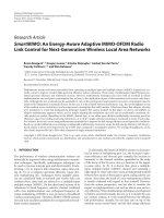
Figure 5. Transmitter/receiver structure for SC-CDMA with rake combining
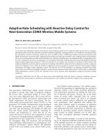
spread signal, resulting in the MC-CDMA signal. MC-CDMA with SF =1is
OFDM. The GI insertion is necessary to avoid the orthogonality destruction among
N
c
subcarriers due to the presence of multipaths with different time delays. The
GI length needs to be larger than the maximum time delay difference among
multipaths. At the receiver, after removing the GI, the received signal is decom-
posed by N
c
-point FFT into N
c
subcarrier components. The distortion of the signal
spectrum due to frequency-selective fading is compensated by using one-tap FDE.
The equalized subcarrier components are parallel-to-serial (P/S) converted into the
time-domain spread signal, followed by despreading as in SC-CDMA receiver.
FDE can be jointly used with antenna diversity reception for further performance
improvement in MC-CDMA. Among various FDE weights, it was shown that
the use of minimum mean square error (MMSE) weight provides the best bit
error rate (BER) performance. This is because the MMSE weight can provide the
best compromise between the noise enhancement and suppression of frequency-
selectivity. MC-CDMA with MMSE-FDE provides much better BER performance
than SC-CDMA with coherent rake combining. Because of this, until recently,
research attention was shifted from SC techniques to MC techniques such as MC-
CDMA and OFDM SF =1. But, as will be shown in this chapter, FDE can
FUNDAMENTALS OF SINGLE-CARRIER CDMA TECHNOLOGIES 87
(a) Transmitter
(b) Power spectrum
FrequencyCarrier frequency
Bandwidth 1/T
c
Data
Channel
coding &
interleaving
Data
modulation
Insertion
of GI
#0
Time-domain
spreading
c(t)
IFFTS/P
Conversion to freq domain
spread signal
MC-CDMA
signal
(c) Receiver
Frequency-domain
equalization
Removal
of GI
De-interleaving
& channel
decoding
Data
demodulation
Recovered
data
P/S
Time-domain
despreading
Received
signal
#N
c
–1
f
c
w(0)
w(k)
c(t)
w(N
c
–1)
Integrate
& dump
FFT
Figure 6. Transmitter/receiver structure for MC-CDMA
also be applied to SC-CDMA with much improved performance compared to rake
combining. SC-CDMA is considered again as a promising access technique similar
to MC-CDMA.
4. FREQUENCY-DOMAIN EQUALIZATION
The application of MMSE-FDE to SC-CDMA can replace the coherent rake
combining with much improved BER performance. First, FDE for SC-CDMA is
shown. However, the residual inter-chip interference (ICI) is present after MMSE-
FDE and this will limit the BER performance improvement. The ICI cancellation
can be used to reduce the residual ICI and hence improve the BER performance.
These are presented here.
4.1 MMSE Equalization
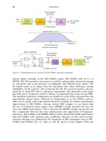
Transmitter/receiver structure of multicode SC-CDMA with FDE is illustrated in
Figure 7. We assume that C data streams are simultaneously transmitted. At the
88 CHAPTER 3
(b) Receiver
Received
data
Data
de-modulation
Removal
of GI
Scramble
code
FFT
AWGN
w(0)
w(k)
w(N
c
–1)
Frequency-domain
equalization
Integrate
and dump
Orthogonal
spreading
code
Multicode
despreading
Insertion
of GI
Data
Data
modulation
(a) Transmitter
Scramble
code
Code-multiplexing
Orthogonal
spreading code
Multicode spreading
IFFT
Figure 7. Multicode SC-CDMA transmitter/receiver structure
transmitter, the uth binary data sequence is transformed into a data modulated
symbol sequence {d
u
n; n = 0 ∼ N
c
/SF −1}, u = 0 ∼ C −1, and then spread
by multiplying an orthogonal spreading sequence c
u
t with spreading factor SF.
The resulting C chip sequences are added and further multiplied by a common
scramble sequence c
scr
t to make the resulting multicode SC-CDMA chip sequence
white-noise like. C is called code-multiplexing order. This is called multicode
spreading. Then, the orthogonal multicode SC-CDMA chip sequence is divided into
a sequence of blocks of N
c
chips each and then the last N
g
chips of each block are
copied as a cyclic prefix and inserted into the GI placed at the beginning of each
block as shown in Figure 8. The GI-inserted multicode SC-CDMA chip sequence
GI SF chips SF chips
• • •
N
c
chipsN
g
chips
Copy
Figure 8. Block structure
FUNDAMENTALS OF SINGLE-CARRIER CDMA TECHNOLOGIES 89
{ˆst t =−N
g
∼N
c
−1} in a block can be expressed, using the equivalent lowpass
representation, as
(3) ˆst =
2E
c
T
c
st mod N
c
where E
c
and T
c
denote the chip energy and the chip duration, respectively, and
st is given by
(4) st =
C−1
u=0
d
u
t/SF
c
u
t mod SF
c
scr
t
for t =0 ∼N
c
−1, where c
u
t=c
scr
t=1 and
x
represents the largest integer
smaller than or equal to x.
The chip block {ˆst t =−N
g
∼N
c
−1} is transmitted over a frequency-selective
fading channel and received by a receiver. After the removal of the GI, the received
chip sequence {rt;t =0 ∼N
c
−1} in a block is decomposed by N
c
-point FFT into
N
c
subcarrier components {Rk; k =0 ∼ N
c
−1} (the terminology “subcarrier” is
used for explanation purpose although subcarrier modulation is not used). The kth
subcarrier component Rk can be written as
(5)
Rk =
N
c
−1
t=0
rt exp
−j2k
t
N
c
=
2E
c
T
c
HkSk +k
where Sk, Hk and k are the kth subcarrier components of st, the channel
gain and the noise component due to the additive white Gaussian noise (AWGN),
respectively. Hk corresponds to Hf, t defined by Eq. (2), but with f =k/(N
c
T
c
;
time dependency of the channel gain is dropped since we are assuming very slow
fading channel for simplicity.
FDE is carried out similar to MC-CDMA. Rk is multiplied by the FDE weight
wk as
(6)
ˆ
Rk = wkRk
=
2E
c
T
c
Sk
ˆ
Hk+
ˆ
k
where
ˆ
Hk = wkHk and
ˆ
k = wkk are the equivalent channel gain
and the noise component after performing FDE, respectively. As the FDE weight,
90 CHAPTER 3
maximal ratio combining (MRC), zero forcing (ZF), equal gain combining (EGC)
and minimum mean square error (MMSE) weights are considered. They are given by
(7) wk =
⎧
⎪
⎪
⎪
⎪
⎪
⎨
⎪
⎪
⎪
⎪
⎪
⎩
H
∗
k for MRC
H
∗
k
Hk
2
for ZF
H
∗
k
Hk
for EGC
H
∗
k
Hk
2
+
C
SF
E
s
N
0
−1
for MMSE
where E
s
/N
0
(=E
c
SF/N
0
is the average received signal energy per data symbol-to-
AWGN power spectrum density ratio and * denotes the complex conjugate operation.
One-shot observation of the equivalent channel gain
ˆ
Hk and the noise
ˆ
k for
MMSE, ZF and MRC weights are illustrated in Figure 9.AnL = 16-path fading
channel is assumed. Also plotted in the figure is the original channel gain Hk. The
MRC weight enhances the frequency-selectivity of the channel after equalization.
Using the ZF weight, the frequency-nonselective channel can be perfectly restored
after equalization (of course, only if the channel estimation is ideal), but the noise
enhancement is produced at the subcarrier where the channel gain drops. However,
the MMSE weight can avoid the noise enhancement by giving up the perfect
restoration of the frequency-nonselective channel (the MMSE weight minimizes
the mean square error between Sk and
ˆ
Rk. Among these FDE weights, the
MMSE weight can provide the best compromise between the noise enhancement and
suppression of frequency-selectivity and therefore, gives the best BER performance.
After MMSE-FDE, N
c
-point IFFT is applied to obtain the time-domain multicode
SC-CDMA chip sequence as
(8)
ˆrt =
1
N
c
N
c
−1
k=0
ˆ
Rk exp
j2t
k
N
c
=
2E
c
T
c
1
N
c
N
c
−1
k=0
ˆ
Hk
st +ˆt +ˆt
where st in the first term represents the transmitted chip sequence, ˆt is the
residual inter-chip interference (ICI) component and ˆt is the noise component.
ˆt can be expressed as
(9) ˆt =
2E
c
T
c
1
N
c
N
c
−1
k=0
ˆ
Hk
⎡
⎣
N
c
−1
=0
=t
s exp
j2k
t −
N
c
⎤
⎦
Note that if
ˆ
Hk = constant, ˆt =0 (i.e., this is the case of ZF-FDE and no ICI
is produced). The residual ICI degrades the achievable BER performance (this is
FUNDAMENTALS OF SINGLE-CARRIER CDMA TECHNOLOGIES 91
0.01
0.1
1
10
Subcarrier index k
|H (k)|
(a) Original channel gain
250
0 50 100 150 200
0.01
0.1
1
10
Subcarrier index k
MMSE
MRC
ZF
(b) Equivalent channel gain
2500 50 100 150 200
Equivalent channel gain
|H (k)|
〈
–10
0
10
Subcarrier index k
ZF
MMSE
MRC
(c) Noise
250050
100
150
200
〈
Noise Re[ Π (k)]
Figure 9. One-shot observation of equivalent channel gain and noice after FDE
92 CHAPTER 3
explained later). Multicode despreading is carried out on ˆrt to obtain the decision
variable for the data modulated symbol sequence {d
u
n; n = 0 ∼ N
c
/SF −1},
u = 0 ∼C −1, as
(10)
ˆ
d
u
n =
1
SF
n+1SF−1
t=nSF
ˆrtc
∗
u
t mod SFc
∗
scr
t
based on which data demodulation is done.
An arbitrary spreading factor SF can be used for the given value of FFT window
size N
c
. This property allows variable rate transmission even when FDE is used in
SC-CDMA systems.
Figure 10 plots the BER performance of multicode SC-CDMA using MMSE-
FDE for SF=16, obtained by computer simulation, as a function of the average
received bit energy-to-AWGN noise power spectrum density ratio E
b
/N
0
. QPSK
data modulation and an L = 16-path frequency-selective Rayleigh fading channel
having a uniform power delay profile (E[h
l
2
=1/L are assumed. For comparison,
1.E–05
1.E–04
1.E–03
1.E–02
Average BER
1.E–01
1.E+00
Average received E
b
/N
0
(dB)
QPSK
N
c
= 256, N
g
= 32
L
= 16-path uniform
power delay profile
SF
= 16
C = 1
4
8
16
×
MMSE-FDE
Rake combining
Theoretical
lower bound
250 5 10 15 20
Figure 10. BER performance of multicode SC-CDMA with MMSE-FDE
FUNDAMENTALS OF SINGLE-CARRIER CDMA TECHNOLOGIES 93
the BER performance of coherent rake combining and theoretical lower-bound are
also plotted. When C =1, MMSE-FDE and rake combining can achieve almost the
same BER performance. However, when C ≥4, the BER performance using rake
combining significantly degrades due to strong ICI and exhibits large BER floors.
MMSE-FDE can always achieve better BER performance than rake combining and
no BER floors are seen. However, although MMSE-FDE provides much better
BER performance, the BER performance degrades as the code-multiplexing order
C increases since the orthogonality distortion among codes is produced due to the
residual ICI ˆt. As the frequency-selectivity becomes stronger (or L increases),
the complexity of the rake receiver increases since more correlators are required
for collecting enough signal power for data demodulation. However, unlike rake
receiver, the complexity of MMSE-FDE receiver is independent of the channel
frequency-selectivity. The use of FDE can alleviate the complexity problem of the
rake receiver arising from too many paths in a severe frequency-selective channel.
These suggest that SC-CDMA with MMSE-FDE is a promising broadband access
as MC-CDMA for 4G wireless networks.
4.2 Inter-chip Interference (ICI) Cancellation
Although MMSE-FDE can significantly improve the BER performance of
orthogonal multicode SC-CDMA, there is still a big performance gap to the
theoretical lower-bound as shown in Figure 10. This is due to the residual ICI after
MMSE-FDE, given by Eq. (9). An ICI cancellation technique can be introduced into
MMSE-FDE to improve the BER performance. The ICI in SC-CDMA with SF=1
is equivalent to the inter-symbol interference (ISI) in the non-spread (i.e., SF=1)
SC transmissions; the ISI cancellation techniques can be found in the literature.
Similar to ISI cancellation for MC-CDMA, ICI cancellation for SC-CDMA can be
carried out either in the time-domain or in the frequency-domain after performing
MMSE-FDE.
For the frequency-domain ICI cancellation, the replicas of frequency components
{Mk; k = 0 ∼ N
c
−1} of the residual ICI ˆt in Eq. (9) are subtracted from
ˆ
Rk k = 0 ∼N
c
−1 after MMSE-FDE. Mk is given by
(11)
Mk =
N
c
−1
t=0
ˆtexp
−j2k
t
N
c
=
2E
c
T
c
ˆ
Hk−
1
N
c
N
c
−1
k
=0
ˆ
Hk
Sk
A joint MMSE-FDE and ICI cancellation is repeated in an iterative fashion so as to
improve the accuracy of the ICI replica generation. Figure 11 shows the structure
of joint MMSE-FDE and ICI cancellation.
94 CHAPTER 3
IFFT
FFT
Multicode
despreading
Data
demodulation
Symbol replica
generation
Multicode
spreading
MMSE weight
& ICI replica
generation
Received chip
sequence
Received
data
ICI replica
w(k)
Iteration
Delay
FFT
–
• • •• • •
• • •• • •
Figure 11. Joint MMSE-FDE and ICI cancellation
The ith iteration is described below. After performing MMSE-FDE with the
MMSE weight w
i
k , ICI cancellation is performed in the frequency-domain as
(12)
˜
R
i
k =
ˆ
H
i
k −
˜
M
i
k
where
ˆ
H
i
k
=w
i
kHk
is the equivalent channel gain and
˜
M
i
k is the
replica of Mk which is given, from Eq. (11), as
(13)
˜
M
i
k =
⎧
⎪
⎨
⎪
⎩
0 for i =0
2E
c
T
c
ˆ
H
i
k −A
i
˜
S
i−1
k for i>0
where
˜
S
i−1
k is the kth frequency component of the soft decision transmitted
chip block replica ˜s
i−1
t (which is generated by feeding back the (i −1)th ICI
cancellation result) and A
i
is given by
A
i
=
1
N
c
N
c
−1
k=0
ˆ
H
i
k(14)
N
c
-point IFFT is performed on
˜
R
i
k k = 0 ∼N
c
−1to obtain the time-domain
chip sequence for multicode despreading.
A series of joint MMSE-FDE and ICI cancellation, N
c
-point IFFT, multicode
despreading, data symbol replica generation, and multicode spreading is repeated a
sufficient number of times. Finally, data-demodulation is carried out to obtain the
received data.
The MMSE weight w
i
k minimizes the mean square error (MSE) Eek
2
for
the given Hk, i.e., E
ek
2
w
i
k =0, where ek is the equalization error
between
˜
R
i
k after the ICI cancellation and Sk of the transmitted signal st
and is defined as
(15) ek =
˜
R
i
k −A
i
Sk
FUNDAMENTALS OF SINGLE-CARRIER CDMA TECHNOLOGIES 95
The MMSE weight is given as
(16) w
i
k =
H
∗
k
i−1
Hk
2
+
E
c
N
0
−1
where
i−1
is an interference factor determined by feeding back the (i −1)th
iteration result and given by
(17)
i−1
≈
N
c
−1
t=0
¯s
i−1
t
2
−
˜s
i−1
t
2
where ¯s
i−1
t is the hard decision replica of transmitted chip block.
The BER performance for the case of SF = 16 is plotted in Figure 12 with
the code-multiplexing order C as a parameter. When C =1, the BER performance
approaches the theoretical lower-bound by about 0.5 dB. As C increases, the BER
1.E–05
1.E–04
1.E–03
Average BER
1.E–02
1.E–01
17
Average received E
b
/ N
0
(dB)
QPSK
L
= 16
SF
= 16
Lower
bound
w/ ICI cancellation (i = 3)
w/o ICI cancellation
C = 1
=
4
=
8
=
16
×
2712
Figure 12. Simulated BER performance with joint MMSE-FDE and ICI cancellation
96 CHAPTER 3
performance without ICI cancellation degrades. This is because a severe orthogo-
nality distortion is produced by the residual ICI. The use of ICI cancellation can
improve the BER performance. When C =16, the E
b
/N
0
reduction from the no ICI
cancellation case is as much as 6.9 dB for BER =10
−4
.
5. SPACE-TIME BLOCK CODING
The antenna diversity technique can be used to increase the received signal-to-noise
power ratio (SNR) and hence improve the transmission performance. There are
two types of antenna diversity: receive diversity and transmit diversity (they can
be jointly used). Receive antenna diversity has been successfully used in practical
systems. Recently, transmit antenna diversity has been gaining much attention since
the use of transmit diversity at a base station can alleviate the complexity problem
of mobile receivers.
Space-time block coded transmit diversity (STTD) can achieve the space diversity
gain without requiring channel information at the transmitter. In MC-CDMA, each
subcarrier component is STTD encoded and then decoded in conjunction with
MMSE equalization. This STTD can be applied to SC-CDMA with MMSE-FDE.
Here, this is called frequency-domain STTD. In frequency-domain STTD, consec-
utive chip blocks are encoded in the frequency-domain.
(a) N
t
=2
STTD encoding for N
t
= 2 is shown in Table 1. Two consecutive chip blocks,
s
e
t t =0 ∼N
c
−1 and s
o
t t =0 ∼N
c
−1, at even and odd time intervals are
decomposed byN
c
-point FFT into N
c
subcarrier components, {S
e
k; k =0 ∼N
c
−1}
and {S
o
k; k =0 ∼N
c
−1}, respectively, for STTD encoding. Then, N
c
-point IFFT
is used to obtain the time-domain coded chip blocks. This encoding requires FFT
and IFFT operations. An equivalent time-domain STTD encoding that requires no
FFT and IFFT operations is shown in. Since
(18)
⎧
⎪
⎪
⎨
⎪
⎪
⎩
1
N
c
N
c
−1
k=0
S
∗
e
k exp
j2t
k
N
c
=s
∗
e
N
c
−t mod N
c
1
N
c
N
c
−1
k=0
S
∗
o
k exp
j2t
k
N
c
=s
∗
o
N
c
−t mod N
c
STTD encoding of Table 1 can be replaced by equivalent time-domain STTD
encoding of Table 2. Equivalent time-domain STTD encoding is illustrated in
Table 1. Frequency-domain STTD encoding for N
t
=2
Time (in chip block) Antenna #0 Antenna #1
Even
1
√
2
S
e
k
1
√
2
S
o
k
Odd −
1
√
2
S
∗
o
k
1
√
2
S
∗
e
k
FUNDAMENTALS OF SINGLE-CARRIER CDMA TECHNOLOGIES 97
Table 2. Equivalent time-domain STTD encoding N
t
=2
Time (in chip block) Antenna #0 Antenna #1
Even
1
√
2
s
e
t
1
√
2
s
o
t
Odd −
1
√
2
s
∗
o
N
c
−t mod N
c
1
√
2
s
∗
e
N
c
−t mod N
c
Figure 13 (note that transmit power from each antenna is halved to keep the same
total transmit power).
At a receiver, after the removal of the GI, the even and odd chip blocks received
by the n
r
th (n
r
=0 ∼N
r
−1) receive antenna are decomposed by N
c
-point FFT into
N
c
subcarrier components {R
en
r
k; k =0 ∼N
c
−1} and {R
on
r
k; k =0 ∼N
c
−1},
respectively. R
en
r
k and R
on
r
k can be written as
(19)
R
en
r
k =
1
√
2
S
e
kH
n
r
0
k +
1
√
2
S
o
kH
n
r
1
k +
en
r
k
R
on
r
k =−
1
√
2
S
∗
o
kH
n
r
0
k +
1
√
2
S
∗
e
kH
n
r
1
k +
on
r
k
where H
n
r
0
k (or H
n
r
1
k represents the N
c
-point Fourier transform of the channel
gain between the n
r
th receive antenna and the 0th (or 1st) transmit antenna and
en
r
k and
on
r
k represent the k-th subcarrier components of the noise in
the received even and odd chip blocks, respectively. STTD decoding for N
t
= 2
is carried out jointly with receive antenna diversity combining, in the frequency-
domain, jointly with MMSE-FDE as
(20)
⎧
⎪
⎪
⎨
⎪
⎪
⎩
˜
S
e
k =
N
r
−1
n
r
=0
w
∗
n
r
0
kR
en
r
k +w
n
r
1
kR
∗
on
r
k
˜
S
o
k =
N
r
−1
n
r
=0
w
∗
n
r
1
kR
en
r
k −w
n
r
0
kR
∗
on
r
k
time
Time-domain
STTD encoding
Insertion
of GI
Antenna #
0
s
e
(t)
s
o
(t)
time
time
Two chip blocks
N
c
chips
even
STTD encoded chip blocks
N
c
+
N
g
chips
GI
Antenna #
1
2
1
s
e
(t)
2
1
−
∗
s
o
(N
c
–
t)
2
1
∗
s
e
(N
c
–
t)
s
o
(t)
2
1
s
o
(N
c
–
t)
2
1
−
∗
s
e
(N
c
–
t)
2
1
∗
s
e
(t)
2
1
s
o
(t)
2
1
even odd
odd
Figure 13. Equivalent time-domain STTD encoding for SC-CDMA
98 CHAPTER 3
In the above, w
0n
r
k and w
1n
r
k are the MMSE weights, given by
(21)
⎧
⎪
⎪
⎪
⎨
⎪
⎪
⎪
⎩
w
n
r
0
k =
H
n
r
0
k
N
r
n
r
=0
1
n
t
=0
H
n
r
n
t
k
2
+
1
2
C
SF
E
s
N
0
−1
w
n
r
1
k =
H
n
r
1
k
N
r
n
r
=0
1
n
t
=0
H
n
r
n
t
k
2
+
1
2
C
SF
E
s
N
0
−1
where C denotes the code multiplexing order. Finally, N
c
-point IFFT is applied
to
˜
S
e
k and
˜
S
o
k to obtain the time-domain chip blocks for despreading and
data demodulation.
(b) N
t
=3 and 4
When N
t
=3 and 4, four consecutive chip blocks s
q
t t =0 ∼N
c
−1, q =0 ∼3,
are encoded. STTD encoding for N
t
=3 and 4 can be expressed, using the matrix
representation, as
(22)
⎛
⎝
s
00
t s
10
t s
20
t s
30
t
s
01
t s
11
t s
21
t s
31
t
s
02
t s
12
t s
22
t s
32
t
⎞
⎠
=
1
√
3
⎛
⎜
⎝
s
0
t −s
∗
1
N
c
−t mod N
c
−s
∗
2
N
c
−t mod N
c
0
s
1
t s
∗
0
N
c
−t mod N
c
0 −s
∗
2
N
c
−t mod N
c
s
2
t 0 s
∗
0
N
c
−t mod N
c
s
∗
1
N
c
−t mod N
c
⎞
⎟
⎠
for N
t
=3
and
(23)
⎛
⎜
⎜
⎝
s
00
t s
10
t s
20
t s
30
t
s
01
t s
11
t s
21
t s
31
t
s
02
t s
12
t s
22
t s
32
t
s
03
t s
13
t s
23
t s
33
t
⎞
⎟
⎟
⎠
=
1
2
⎛
⎜
⎜
⎜
⎝
s
0
t −s
∗
1
N
c
−t mod N
c
−s
∗
2
N
c
−t mod N
c
0
s
1
t s
∗
0
N
c
−t mod N
c
0 −s
∗
2
N
c
−t mod N
c
s
2
t 0 s
∗
0
N
c
−t mod N
c
s
∗
1
N
c
−t mod N
c
0 s
2
t −s
1
t s
0
t
⎞
⎟
⎟
⎟
⎠
for N
t
=4
where {s
qn
t
t; t =0 ∼ N
c
−1} is the coded chip block to be transmitted from the
n
t
th transmit antenna in the qth time interval.
STTD decoding are carried out, in the frequency-domain, jointly with MMSE-
FDE as
(24)
⎛
⎝
˜
S
0
k
˜
S
1
k
˜
S
2
k
⎞
⎠
=
⎛
⎜
⎜
⎜
⎜
⎜
⎜
⎜
⎝
N
r
−1
n
r
=0
R
0n
r
kw
∗
n
r
0
k +R
∗
1n
r
kw
n
r
1
k +R
∗
2n
r
kw
n
r
2
k
N
r
−1
n
r
=0
R
0n
r
kw
∗
n
r
1
k −R
∗
1n
r
kw
n
r
0
k +R
∗
3n
r
kw
n
r
2
k
N
r
−1
n
r
=0
R
0n
r
kw
∗
n
r
2
k −R
∗
2n
r
kw
n
r
0
k −R
∗
3n
r
kw
n
r
1
k
⎞
⎟
⎟
⎟
⎟
⎟
⎟
⎟
⎠
for N
t
=3
FUNDAMENTALS OF SINGLE-CARRIER CDMA TECHNOLOGIES 99
and
(25)
⎛
⎝
˜
S
0
k
˜
S
1
k
˜
S
2
k
⎞
⎠
=
⎛
⎜
⎜
⎜
⎜
⎜
⎜
⎜
⎝
N
r
−1
n
r
=0
R
0n
r
kw
∗
n
r
0
k +R
∗
1n
r
kw
n
r
1
k
+R
∗
2n
r
kw
n
r
2
k +R
3n
r
kw
∗
n
r
3
k
N
r
−1
n
r
=0
R
0n
r
kw
∗
n
r
1
k −R
∗
1n
r
kw
n
r
0
k
−R
2n
r
kw
∗
n
r
3
k +R
∗
3n
r
kw
n
r
2
k
N
r
−1
n
r
=0
R
0n
r
kw
∗
n
r
2
k +R
1n
r
kw
∗
n
r
3
k
−R
∗
2n
r
kw
n
r
0
k −R
∗
3n
r
kw
n
r
1
k
⎞
⎟
⎟
⎟
⎟
⎟
⎟
⎟
⎠
for N
t
=4
where R
qn
r
k is the kth frequency component of the chip block received by the
n
r
th receive antenna in the qth time interval, and w
n
r
n
t
k is the MMSE weight
given as
1.E–05
Average BER
1.E–04
1.E–03
1.E–02
1.E–01
Average received E
b
/N
0
(dB)
QPSK
N
c
= 256, N
g
= 32
SF
= 16
L = 16, N
t
= 2, N
r
= 1
w/STTD
w/o STTD
C = 1
= 4
=
8
=
16
×
200 5 10 15
Figure 14. BER performance of SC-CDMA using STTD with N
t
=2 and N
r
=1
100 CHAPTER 3
(26) w
n
r
n
t
k =
H
n
r
n
t
k
1
N
t
N
t
−1
n
t
=0
N
r
−1
n
r
=0
H
n
r
n
t
k
2
+
C
SF
E
s
N
0
−1
Frequency-domain STTD with N
t
= 2 and N
r
= 1 is evaluated by the computer
simulation. We assume N
c
= 256, N
g
= 32, coherent QPSK data-modulation, and
a chip-spaced L =16-path frequency-selective block Rayleigh fading channel with
uniform power delay profile ( = 0 dB), and ideal channel estimation. The BER
performance using frequency-domain STTD is plotted in Figure 14 for SF=16. For
comparison, the single transmit antenna case (N
t
=1) is also plotted. The transmit
diversity gain similar to that of two-antenna receive diversity (N
r
=2) using MRC
is obtained, but with a 3dB power penalty (this is because the transmit power from
each antenna is halved to keep the same total transmit power).
6. MIMO SPACE DIVISION MULTIPLEXING
High-speed data services of 100M∼1Gbps are demanded in the next gener-
ation wireless systems. However, the available bandwidth is limited. Space
division multiplexing (SDM) is a promising technique to achieve highly spectrum-
efficient transmission. In SDM, different data sequences are transmitted in
parallel from different transmit antennas using the same carrier frequency.
At a receiver, a superposition of different data sequences transmitted from
different antennas is received. A lot of research attention has been paid to
the signal separation/detection schemes, e.g., maximum likelihood detection
(MLD), ZF detection, MMSE detection and vertical-Bell Laboratories layered
space-time architecture (V-BLAST). For high-speed data transmissions, the
channels become severely frequency-selective and the BER performance of
SC-CDMA using SDM degrades due to the inter-chip interference (ICI) and inter-
ference from other antennas. Therefore, the receiver must have two tasks: signal
separation/detection and channel equalization.
6.1 Transmit/Receive Signal Representation
Orthogonal multicode SC-CDMA is considered. Figure 15 illustrates the trans-
mitter/receiver structure of (N
t
, N
r
SDM, where N
t
and N
r
denote the number of
N
r
Received
data
Frequency-domain
signal processing
FFT
Transmit
Data
Data
mod.
Multicode
spreading
+
scrambling
N
t
antennas
N
r
antennas
Insertion
of GI
S/P
Insertion
of GI
Removal
of GI
Removal
of GI
• • •
• • •
• • •
• • •
Figure 15. Transmitter/receiver structure for (N
t
, N
r
SDM
FUNDAMENTALS OF SINGLE-CARRIER CDMA TECHNOLOGIES 101
transmit antennas and that of receive antennas, respectively. At the transmitter, a
binary information sequence is data-modulated and converted to C parallel streams
by serial/parallel (S/P) conversion. Then, each stream is spread by using a different
orthogonal spreading code with the spreading factor SF. The resulting C parallel chip
streams are added and multiplied by a scramble sequence for making the resulting
orthogonal multicode SC-CDMA signal noise-like. The full code-multiplexed
SC-CDMA (i.e., C = SF) has the same data rate as the non-spread SC transmission.
The code-multiplexed SC-CDMA signal is converted by S/P converter to N
t
parallel
streams s
n
t
t, n
t
=0 ∼N
t
−1. Each stream is divided into a sequence of blocks of
N
c
chips each. After inserting the GI, N
t
chip blocks are transmitted simultaneously
from N
t
transmit antennas.
A superposition of N
t
transmitted chip blocks is received by N
r
receive antennas.
After the removal of GI, the chip block r
n
r
t; t = 0 ∼ N
c
−1} received on the
n
r
th receive antenna is decomposed byN
c
-point FFT into N
c
frequency components
{R
n
r
k; k =0 ∼N
c
−1} as
R
n
r
k =
N
c
−1
t=0
r
n
r
t exp
−j2k
t
N
c
=
2E
c
T
c
N
t
−1
n
t
=0
H
n
r
n
t
kS
n
t
k +
n
r
k(27)
where E
c
is the chip energy, T
c
is the chip length, H
n
r
n
t
k is the complex channel
gain between the n
t
th transmit antenna and the n
r
th receive antenna, S
n
t
k is the
kth frequency component of s
n
t
t, and
n
r
k is the noise.
6.2 Signal Separation/Detection
Since the channel is frequency-selective, signal separation/detection and frequency-
domain equalization need to be jointly performed. Below, frequency-domain MLD
(FD-MLD), two dimensional (2D)-ZF FDE detection, 2D-MMSE FDE detection,
FD V-BLAST and iterative joint MMSE-FDE/FD-parallel interference cancellation
(PIC) are introduced.
(a) FD-MLD
MLD computes the log-likelihood metric as
(28) =
N
c
−1
k=0
N
r
−1
n
r
=0
R
n
r
k −
2E
c
T
c
N
t
−1
n
t
=0
H
n
r
n
t
k
˜
S
n
t
k
2
where
˜
S
n
t
k is the kth frequency component of the candidate chip block {˜s
n
t
t;
t =0 ∼N
c
−1}. MLD finds the best combination of N
t
transmitted chip blocks which
102 CHAPTER 3
provides the smallest log-likelihood metric, i.e., ˆs
0
t ˆs
n
t
t ˆs
N
t
−1
t =
min
˜s
n
t
t
. After de-spreading and de-scrambling, the most reliable symbol sequence
is obtained. MLD provides the best transmission performance; however, it has
a drawback of quite large computational complexity since the number of metric
computations is as much as 2
N
t
·N
c
·B
, where B is the number of bits per symbol.
(b) 2D-ZF FDE detection and 2D-MMSE FDE detection
In 2D-ZF FDE detection and 2D-MMSE FDE detection, the kth frequency
component
ˆ
R
n
t
k of the n
t
th transmitted chip block is obtained as
(29)
ˆ
R
n
t
k = w
n
t
kRk
where Rk = R
0
k ···R
N
r
−1
k
T
is the N
r
-by-1 received signal vector and
w
n
t
k = w
0n
t
k ···w
N
r
−1n
t
k is the 1-by-N
r
weight vector. 2D-ZF FDE
weight can be derived by Moore-Penrose generalized inversed matrix. The MMSE
weight minimizes the MSE Eek
2
between the signal transmitted from the n
t
th
antenna and the received signal after performing FDE, where ek is defined as
(30) ek =
2E
c
T
c
S
n
t
k −w
n
t
kRk
w
n
t
k can be derived from as
(31) w
n
t
k =
⎧
⎪
⎪
⎨
⎪
⎪
⎩
H
H
kHk
−1
n
t
H
H
k for 2D-ZF
H
H
n
t
k
HkH
H
k +
C ·E
c
N
0
−1
I
N
r
−1
for 2D-MMSE
where Hk =H
0
k ··· H
N
t
−1
k is the N
r
-by-N
t
complex channel gain matrix
whose element of the n
r
th row and the n
t
th column is H
n
r
n
t
k, H
H
kHk
−1
n
t
is
the n
t
th row vector of the inverse matrix of H
H
kHk and I
N
r
is the N
r
-by-N
r
identity matrix. N
c
-point IFFT is performed on {
ˆ
R
n
t
k; k = 0 ∼N
c
−1} to obtain
the time-domain chip block. After performing despreading and de-scrambling, the
received symbol sequence is recovered.
2D-ZF FDE weight gives the perfect separation of transmitted chip blocks since
a frequency-nonselective channel is restored (if the channel estimation is ideal).
However, the BER performance using 2D-ZF FDE detection degrades due to the
noise enhancement. The 2D-MMSE FDE weight can reduce simultaneously the ICI
and the interference from other antennas while suppressing the noise enhancement.
Therefore, 2D-MMSE FFDE gives much better transmission performance.
(c) FD V-BLAST
In FD V-BLAST, the signal detection and interference cancellation are repeated
until all the transmitted signals are detected according to the descending order of the
received signal reliability. Without loss of generality, the transmit antenna having
FUNDAMENTALS OF SINGLE-CARRIER CDMA TECHNOLOGIES 103
the highest reliability is assumed to be the 0th transmit antenna, followed by the
1st, 2nd, …, and (N
t
−1)th antennas. The n
t
th signal component
ˆ
R
n
t
k is obtained,
by performing 2D-MMSE FDE detection (or 2D-ZF FDE detection), as
(32)
ˆ
R
n
t
k = w
n
t
kR
k
where R
k = R
0
k ···R
N
r
−1
k
T
is the received signal vector after inter-
ference cancellation of the signals transmitted from the 0 ∼n
t
−1)th antennas and
w
n
t
k =w
0n
t
k ···w
N
r
−1n
t
k is the 1-by-N
r
MMSE FDE or ZF FDE weight
vector given by
(33) w
n
t
k =
⎧
⎪
⎨
⎪
⎩
H
H
kH
k
−1
n
t
H
H
k for 2D-ZF
H
H
n
t
k
H
kH
H
k +
C·E
c
N
0
−1
I
N
r
−1
for 2D-MMSE
where H
k = H
n
t
k ··· H
N
t
−1
k is the N
r
-by-(N
t
−n
t
channel gain matrix
obtained by deleting the 0 ∼n
t
−1)th channel gain column vector from the N
r
-by-
N
t
channel gain matrix H(k. The n
t
th time-domain received chip block is obtained
by carrying out N
c
-point IFFT on
ˆ
R
n
t
k k = 0 ∼ N
c
−1. After performing
despreading and descrambling, the received symbol sequence is recovered.
For the detection of the signal transmitted from the (n
t
+1)th antenna, the inter-
ference replicas
˜
S
n
t
k, n
t
= 0 ∼ n
t
, are generated and subtracted from R
n
r
k
as
(34) R
n
r
k = R
n
r
k −
2E
c
T
c
n
t
n
t
=0
H
n
r
n
t
k
˜
S
n
t
k
for the detection of the chip block transmitted from the (n
t
+1)th antenna. The
above operation is repeated, until all the transmitted signals are detected.
(d) Iterative joint MMSE-FDE/FD-PIC
The interference from other transmit antennas are suppressed by joint MMSE-
FDE and FD-PIC. However, since the interference suppression is not sufficient,
joint MMSE-FDE and FD-PIC is repeated. At the initial stage ( i = 0), 2D-MMSE
FDE is used. The interfering signal replicas
˜
S
i−1
n
t
k k = 0 ∼ N
c
− 1,
n
t
= 0 ∼ N
t
−1 = n
t
, at the (i −1)th iteration are generated and are subtracted
from the received signal R
n
r
k as
(35) R
i
n
r
n
t
k = R
n
r
k −
2E
c
T
c
N
t
−1
n
t
=0=n
t
H
n
r
n
t
k
˜
S
i−1
n
t
k
Since the resulting signal is close to that for the single antenna transmission case,
1D-MMSE FDE is used instead of 2D-MMSE FDE for i ≥1. Joint 1D-MMSE FDE
is performed as
(36)
ˆ
R
i
n
t
k = w
i
n
t
kR
i
n
t
k
104 CHAPTER 3
where R
i
n
t
k = R
i
0n
t
k ···R
i
N
r
−1n
t
k
T
and w
i
n
t
k = w
i
0n
t
k ···
w
i
N
r
−1n
t
k is the 1D-MMSE FDE weight vector, given by
(37) w
i
n
t
k = H
H
n
t
k
H
H
n
t
kH
n
t
k +
C ·E
c
N
0
−1
−1
6.3 BER Performance
The BER performance of full code-multiplexed SC-CDMA using (4,4)SDM is
plotted in Figure 16 as a function of the average received E
b
/N
0
per receive antenna.
N
t
×N
r
channels are independent Rayleigh fading channels having an L = 16-
path uniform power delay profile ( =0dB). Iterative joint MMSE-FDE/FD-PIC is
superior to 2D-ZF FDE detection, 2D-MMSE FDE detection, and FD V-BLAST.
For comparison, the BER performance of the perfect PIC (i.e., the interference from
1.E – 05
1.E
– 04
1.E
– 03
1.E
– 02
1.E
– 01
1.E
+ 00
Average received E
b
/N
0
per antenna (dB)
2D-ZF FDE detection
2D-MMSE FDE detection
FD V-BLAST
Perfect FD-PIC
SC-CDMA (4,4)SDM
QPSK mod.
SF
= C = 64, N
c
= 256, L = 16,
uniform power delay profile
(β = 0)
Perfect
FD-PIC
Iterative joint
MMSE-FDE/
FD-PIC
2D-ZF FDE detection
2D-MMSE FDE detection
FD V-BLAST
Iterative joint MMSE-FDE/FD-PIC(
i
=
4)
302520151050
Average BER
Figure 16. BER performance of full code-multiplexed SC-CDMA using (4,4) SDM
FUNDAMENTALS OF SINGLE-CARRIER CDMA TECHNOLOGIES 105
other antennas is perfectly cancelled) is also plotted. The E
b
/N
0
degradation, for
BER=10
−4
, of iterative joint MMSE-FDE/FD-PIC from the perfect PIC is only
about 0.1dB. A reason for this superiority of iterative FD-PIC is discussed below.
Only an (N
r
−N
t
+1)-order antenna diversity gain can be obtained by 2D-ZF
FDE detection and 2D-MMSE FDE detection. The BER performance with 2D-
ZF FDE detection degrades due to the noise enhancement. In FD V-BLAST, the
transmitted signals are detected according to the descending order of signals’ relia-
bility. After performing signal detection, the detected signal is subtracted from
the received signal by using its replica and then the corresponding channel gain
vector is deleted from the N
r
-by-N
t
channel gain matrix. For the detection of the
signal transmitted from the n
t
th antenna n
t
= 0 ∼ N
t
−1), the N
r
-by-(N
t
−n
t
channel gain matrix is used. As a consequence, a diversity order of between
(N
r
−N
t
+1) and N
r
is obtained by FD V-BLAST. On the other hand, iterative
joint MMSE-FDE/FD-PIC can always obtain the N
r
th-order diversity gain.
7. BLOCK SPREAD CDMA
Relying on orthogonal spreading codes, SC-CDMA allows simultaneous trans-
missions from multiple users. However, as the chip rate increases, multipath
channels become time-dispersive and frequency-selective fading is produced. The
frequency-selective fading causes ICI. In the downlink (base-to-mobile) trans-
mission, different users’ data sequences are spread by orthogonal spread codes and
are code-multiplexed. The ICI destroys the code orthogonality at an MS receiver
and gives rise to the downlink multi-access interference (MAI). The downlink
MAI severely limits the performance of single-user rake receivers. The use of
MMSE-FDE can exploit the channel frequency-selectivity as well as suppressing the
downlink MAI and therefore improve the downlink BER performance as discussed
in Section 4. However, in the uplink (mobile-to-base) transmission, different users’
signals go through different channels and are asynchronously received, thereby
producing the uplink MAI. Unfortunately, the uplink MAI cannot be sufficiently
suppressed by single-user MMSE-FDE. Multiuser detection (MUD), can suppress
the uplink MAI. However, its computational complexity grows exponentially with
the number of users. Block spreading can be used to convert the MUD problem
into a set of equivalent single-user equalization problems.
7.1 One-dimensional Block Spreading
One-dimensional (1D) block spreading technique proposed in is shown
in Figure 17. The uth user’s data block consisting of N
c
symbols,
d
u
=[d
u
(0),…,d
u
N
c
− 1)]
T
, is block spread by using a spreading code
c
u
=[c
u
(0),…,c
u
(SF
u
−1
T
. The result can be expressed as an SF
u
×N
c
matrix
S
u
as
(38) S
u
=c
u
d
T
u
106 CHAPTER 3
chip time
write
Data
symbol
read
block time
N
c
chips
c
u
Figure 17. 1D block spreading
Chips from matrix S
u
are transmitted row-by-row over SF
u
block periods, which
means that N
c
chips are transmitted in each block. The mth chip block is represented
by the N
c
×1 vector as
(39) x
u
m = c
m
m
d
u
0 ···d
u
N
c
−1
T
The signal to be transmitted can be expressed, using equivalent lowpass represen-
tation, as
(40) s
u
=
2E
c
T
c
x
T
u
0 ··· x
T
u
SF
u
−1
T
where E
c
is the chip energy, T
c
is the chip duration. After the insertion of N
g
-chip
GI, the uth user’s signal is transmitted.
A superposition of U users’ faded signals is received, via L-path fading channels,
by the BS’s receiver. The sum of the maximum time delay of the channel and the
timing offsets among different users is assumed to be within the GI. After the GI
removal, the received signal vector r =r0rSF
u
N
c
−1
T
with length SF
u
N
c
chips is given by
(41) r =
2E
c
T
c
U−1
u=0
˜
H
u
s
u
+
where
˜
H
u
= diag H
u
0H
u
SF
u
−1 is the uth user’s channel matrix
with H
u
m being the N
c
×N
c
channel matrix at the mth block time and
= 0SF
u
N
c
−1
T
is the noise vector with zero-mean and variance
2N
0
/T
c
(N
0
is the AWGN one-sided power spectrum density). Because of the GI
insertion, H
u
m is a circulant Toeplitz matrix with the first column given as
[h
u0
m,…,h
uL−1
m,0,…,0]
T
, where h
ul
m is the lth path gain of the uth user’s
FUNDAMENTALS OF SINGLE-CARRIER CDMA TECHNOLOGIES 107
channel at the mth block time. r is written into an SF
u
×N
c
matrix row-by-row as
R
u
and then despread by using c
u
as
(42)
ˆ
r
u
=
1
SF
u
c
H
u
R
u
T
=
2E
c
T
c
H
u
d
u
+
U−1
u
=0
u
=u
2E
c
T
c
H
u
d
u
+
where the 1st and 2nd terms are respectively the desired signal and the MAI with
(43)
⎧
⎪
⎪
⎨
⎪
⎪
⎩
H
u
=
1
SF
u
SF
u
−1
m=0
c
∗
u
mc
u
mH
u
m
=
1
SF
u
c
H
u
T
Here, is the SF
u
×N
c
noise matrix, whose xth row and yth column element is
x ·SF
u
+y, and is an N
c
×1 vector whose elements are independent zero-mean
complex Gaussian variables with variance 2N
0
/T
c
/SF
u
. If the channel is time-
invariant (i.e., H
u
m = H
u
0 for m = 0 ∼SF
u
−1), the MAI is removed since
c
H
u
c
=
u
SF
u
u −u
, where · is the delta function.
7.2 Two-dimensional Block Spreading
1D block spread SC-CDMA is a single-rate transmission. In the next generation
mobile communications, a flexible support of low-to-high multi-rate services is
required. The suppression of MAI to increase the link capacity in a mutli-rate
environment is a challenging task. Two-dimensional (2D) block spreading using
orthogonal variable spreading factor (OVSF) codes can remove the MAI while
allowing multi-rate transmissions. 2D block spreading also achieves the time- and
frequency-domain diversity gains.
A transmitter/receiver structure of 2D block spread SC-CDMA is illustrated in
Figure 18. The data symbol to be transmitted is spread in two dimensions, as shown
in Figure 19. The overall spreading factor is SF
u
= SF
t
u
×SF
f
u
, where SF
f
u
is the
spreading factor of chip-time spreading and SF
t
u
is that of block-time spreading.
2D block spread SC-CDMA includes the conventional SC-CDMA and 1D block
spread SC-CDMA as its special cases; 2D block spread SC-CDMA becomes
the conventional SC-CDMA when SF
t
u
= 1, while it becomes 1D block spread
SC-CDMA when SF
f
u
=1.
Let’s consider a block transmission of N
c
/SF
f
u
data symbols. The data symbol
vector d
u
= d
u
0 d
u
N
c
/SF
f
u
−1
T
is spread by a 2D block spreading code
C
u
with the overall spreading factor SF
u
as
(44) S
u
=C
u
⊗d
T
u
108 CHAPTER 3
Insertion
of GI
MS #u
Mod.
N
c
-FFT
BS
.
.
.
.
.
.
.
.
Block
despreading
(SF
u
)
t
Chip
despreading
(SF
u
)
f
FDE
N
c
-IFFT
Channel
AWGN
MAI
N
c
chips
2D block spreading
(SF
u
= SF
u
x SF
u
)
t
f
write
read
s
u
(t)
T
c
2E
c
N
c
chips
read
Transmit
data
Received
data
Removal
of GI
Figure 18. 2D block spread SC-CDMA transmitter/receiver
N
c
chips
chip time
read
block time
t
c
u
f
c
u
Figure 19. 2D block spreading
where ⊗ denotes the Kronecker product and C
u
is an SF
t
u
×SF
f
u
matrix and can be
written as
(45) C
u
=c
t
u
c
f
u
T
with c
t
u
and c
f
u
being respectively the column and row spreading codes, given by
(46)
c
t
u
=
c
t
u
0c
t
u
SF
t
u
−1
T
c
f
u
=
c
f
u
0c
f
u
SF
f
u
−1
T
c
f
u
is used for multi-rate transmissions and SF
f
u
can be arbitrarily set according to
the requested data rate independently of the FFT block size N
c
, but SF
f
u
≤ N
c
. c
t
u
FUNDAMENTALS OF SINGLE-CARRIER CDMA TECHNOLOGIES 109
is used for orthogonal multi-user multiplexing without MAI. In order to maintain
the orthogonality among different users, SF
t
u
should be as small as possible.
7.3 Code Assignment
c
t
u
and c
f
u
can be selected from OVSF codes. OVSF codes are generated by the code
tree, as shown in Figure 20. The data rates may be different for different users. c
t
u
should be orthogonal for different users while c
f
u
is not necessary orthogonal. If the
number U of users is U =2
k
(k=01, all users can be assigned SF
t
u
= 2
k
.If
2
k−1
<U<2
k
,(2
k
−U users among U users can be assigned SF
t
u
= 2
k−1
and the
other (2U −2
k
users can be assigned SF
t
u
=2
k
. After setting the value of SF
t
u
, SF
f
u
can be set equal to SF
f
u
=SF
u
/SF
t
u
for the given overall spreading factor SF
u
.By
doing so, all U users’ signals can be orthogonal.
For simplicity, we assume that the data rate is the same for all users and
the overall spreading factor is SF
u
= SF. Hence, we use SF
t
u
SF
f
u
= USF/U.
Consider SF = 16. If U =8, c
t
u
is selected from {c
8
m
; m = 0 ∼ 7}, e.g., c
t
u
= c
8
5
=
1 −1 1 −1−1 1 −11
T
in Figure 20, and c
f
u
can be selected from {c
2
m
; m =0 ∼
1}. If U =4 c
t
u
is selected from {c
4
m
; m =0 ∼3}, e.g., c
t
u
=c
4
2
=1−1 1 −1
T
, and
c
f
u
can also be selected from {c
4
m
; m = 0 ∼ 3}. If U = 2, then c
t
u
is selected from {c
2
m
;
m = 0 ∼ 1}, e.g., c
t
u
= c
2
1
= 1 −1
T
, and c
f
u
can be selected from {c
8
m
; m = 0 ∼ 7}.
When U = 1, 2D block spreading reduces to the conventional 1D spreading.
7.4 BER Performance
The BER performance of 2D block spread SC-CDMA using single-user MMSE-
FDE is compared, in Figure 21, with conventional SC-CDMA using MMSE-MUD
8
c
2
=[1,1,-1,-1,1,1,-1,-1]
T
8
c
3
=[1,1,
−1,−1,−1,−1, 1,1]
T
8
c
5
=[1,
−1,1,−1,−1,1,−1,1]
T
8
c
4
=[1,
−1,1,−1,1,−1, 1,−1]
T
8
c
1
=[1,1,1,1,
−1,−1,−1,−1]
T
8
c
7
=[1,
−1,−1,1,−1,1,1,−1]
T
8
c
6
=[1,
−1,−1,1,1,−1,−1,1]
T
4
c
0
=(1,1,1,1)
4
c
2
=[1,
−1,1,−1]
T
4
c
3
=[1,
−1,−1,1]
T
4
c
1
=[1,1,
−1,−1]
T
2
c
0
=[1,1]
T
N=1
N=2
N=4
N=8
2
4
8
U=1
8
c
0
=[1,1,1,1,1,1,1,1]
T
2
c
1
=[1,
−1]
T
1
c
0
=1
Figure 20. OVSF code tree
110 CHAPTER 3
10
–1
2
U = 16
U
= 8
U
= 1
2D block spread SC-CDMA
Conventional SC-CDMA
DS U
1
8
16
QPSK
L
= 16, uniform profile (β = 0dB), f
D
T = 10
–4
Average received E
b
/N
0
(dB)
10
–2
10
–3
10
–4
10
–5
16141210864
Average BER
Figure 21. BER performance comparison of 2D block spread and conventional SC-CDMA
when SF = 16
when SF = 16. For block spread SC-CDMA, SF
t
u
SF
f
u
= U 16/U is assumed
for all users. When the system is lightly loaded (i.e., U = 8), conventional
SC-CDMA using MUD exhibits better BER performance since the MAI is less
severe. However, when the system is heavily loaded (i.e., U ≈ SF), the BER
performance of conventional SC-CDMA with MUD severely degrades. Even
when U =16, 2D block spread SC-CDMA provides better BER performance than
conventional SC-CDMA.
The block spreading technique can also be applied to MC-CDMA. The chip-
time spreading in 2D block spread SC-CDMA corresponds to the frequency-
domain spreading in the case of 2D block spread MC-CDMA. Figure 22
compares the BER performances of 2D block spread SC- and MC-CDMA
when SF = 16. In 2D block spread SC-CDMA, the data symbol is always
spread over all subcarriers, yielding large frequency-diversity gain irrespective
of SF
f
u
. However, SC-CDMA suffers from ICI. On the other hand, in the case
of MC-CDMA, the data symbol is spread over only SF
f
u
subcarriers. When
U = 1, 2D block spread MC-CDMA performs slightly better than SC-CDMA
since no ICI is present in MC-CDMA. As U increases, the value of SF
f
u
must be decreased and therefore, frequency-diversity gain becomes smaller in
MC-CDMA and the ICI suppression become weaker in SC-CDMA. When U =16