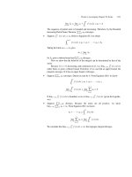
An Experimental Approach to CDMA and Interference Mitigation phần 10 ppt
Bạn đang xem bản rút gọn của tài liệu. Xem và tải ngay bản đầy đủ của tài liệu tại đây (676.43 KB, 29 trang )
246 Chapter
6
the power spectrum of the I component at the output of the CMF. The spec-
tral image is located at
172.84
cd
Rf
MHz and the out of band noise
power reduction performed by the digital front end as a whole is apparent if
we compare this spectrum with the one in Figure 6-18.
Time domain signals can be displayed either via a digital scope con-
nected to the plug in DAC board, or via the ‘virtual scope’ provided by the
BoxView tool. In this context Figure 6-23 sketches the I interpolator output
when the (non-orthogonal) pilot is the only active channel
1
.
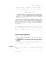
Figure 6-23. Interpolator output signal, useful channel plus pilot with P/C = 30 dB.
Figure 6-24. AGC gain acquisition transient.
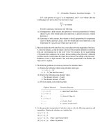
Figure 6-24 shows the acquisition transient of the AGC gain signal, as
displayed on the visualization tool of the BoxView DSP software. The signal
is read at symbol time by means of the DSP interface, and the DSP stores its
value in the data memory, so as it can be read by the Master PC for visuali-
zation. The observation window time amounts at about to 250 symbol inter-
1
As the generation software did not allow the transmission without the reference channel,
we emulated the pilot only condition by setting P/C = 30 dB.
6. Testing and Verification of the MUSIC CDMA Receiver 247
vals. The agreement with previously produced bit true simulation results is
excellent.
Figure 6-25 displays the contents of the internal accumulator of the pilot-
channel correlator in the SAC unit, when
32
b
R kbit/s, 1024
c
R kchip/s
(
64 L
) and no noise is affecting the transmission. The resulting waveform
is a periodic ramp (the pilot channel is unmodulated), whose period equals
the pilot code repetition length (i.e., the symbol period interval)
61/1 |
ss
RT
Ps.
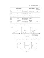
Figure 6-25. Internal status of the I pilot correlator of the digital AGC.
Figure 6-26 shows the time evolution of signal fract_del generated by
the CCTU and controlling the re-sampling epoch input to the linear interpo-
lator unit. This signal updated at symbol time is a ramp as the result of the
(constant) clock frequency shift between transmitter and receiver, which
causes the optimum chip sampling epoch to drift uniformly.
Figure 6-26. CCTU fract_del signal.
Similar debugging features were added to the FPGA implementation of
the EC-BAID detector; they rely on the configuration of two control signals
248 Chapter
6
in order to select a proper output for the PROTEO-II breadboard. Selection
is made according to Tables 6-6 and 6-7.
Table 6-6. Auxiliary output configuration.
Test_sel (2 bits) Auxiliary output (8 bits)
00 CR output symbols (4 + 4 bits)
01 CPRU (Carrier Phase Recovery Unit) phase
10 AGC level
11 Norm of the x
e
vector
Table 6-7. PROTEO-II output configuration.
Swap_sel (1 bit) PROTEO-II output (8 bits)
0 EC-BAID output symbols (4 + 4 bits)
1 EC-BAID / Auxiliary outputs multiplexed
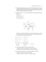
Figure 6-27. EC-BAID internal outputs timing diagram.
Figure 6-28. EC-BAID outputs with no interferers and Eb/No of.
The configuration parameter Test_sel selects the kind of auxiliary out-
put to be provided, while
Swap_sel determines the behavior of the bread-
board outputs: when
Swap_sel is ‘0’ the I/Q EC-BAID outputs are sent on
6. Testing and Verification of the MUSIC CDMA Receiver 249
the bus, whilst with
Swap_sel equal to ‘1’ the I output of the EC-BAID is
multiplexed with the one of the auxiliary interference-mitigating correlator,
according to the timing diagram in Figure 6-27.
Figure 6-29. Phase acquisition with frequency offset.
Figure 6-30. |x| transient.
All of the four observable signals as in Table 6-7 were used to test the
match between our FORTRAN bit true model and VHDL design, as detailed
in Chapters 4 and 5. As an example, Figure 6-28 shows the EC-BAID soft
output for the case of an ideal transmission with no interferers and
0
/ NE
b
approaching infinite. Figure 6-29 shows a typical phase acquisition curve
when the CPRU operates with a residual frequency error at the EC-BAID
input. Finally, Figure 6-30 is a ‘summary’ of the acquisition phase of the
250 Chapter
6
EC-BAID since it represents the norm of the adaptive vector
e
x that gives
interference mitigating capability (see Chapter 3). This quantity allows to
detect whether the EC-BAID is in its steady state or not, and was also used
to detect and correct timing violations in the critical path of our FPGA de-
sign. Timing violations look like sharp spikes in the curve of x that of
course are not present in Figure 6-30 since it represents a sample of correct
operation.
3. OVERALL RECEIVER PERFORMANCE
Once the debugging phase was complete a set of receiver performance
measurements (mainly in the form of BER curves) was planned and carried
out. The goal was to cover as extensively as possible the transmission condi-
tions and system configurations listed in the project specifications. Accord-
ing to Table 6-1, the code length L was varied into the range 32
–128, the
chip rate R
c
spanned the interval 128 kchip/s to 2048 kchip/s and conse-
quently the symbol rate R
s
ranged from 1 to 32 ksymb/s.
All of the numerical results presented hereafter were derived in the pres-
ence of a synchronous non-orthogonal E-Gold pilot signal code division
multiplexed with the useful traffic channels as discussed in Section 3 of
Chapter 2. The pilot to useful carrier power ratio P/C was set to 6 dB as a
good trade off between interference level owed to residual cross correlation
and sync accuracy provided by pilot aided operations. We also defined as
mild, medium and heavy load conditions those corresponding to a total num-
ber of active channels (encompassing the useful, the pilot and the interfering
ones)
4NL
,
2NL
and
34NL
, respectively. The interfering chan-
nels are equi-powered and the ‘useful carrier to single-interferer’ power ratio
is set to
0dBCI . The update step size of the EC-BAID algorithm, intro-
duced in Chapter 3, was
413
1044.12
u
BAID
J
for mild and medium load-
ing and
515
1005.32
u
BAID
J
for heavy loading. The leak factor, also
defined in Chapter 3 was set to the optimum value
3
2 0.125
leak
J .
The benchmarks for our experimental results were the corresponding
BER curves obtained after floating point and/or bit true software simula-
tions. In particular, we resorted to long simulations to increase the BER es-
timation accuracy as much as possible. Two different configurations were
selected: 200K symbols long transient and 100K symbol of observation for
BER estimation when
13
2
BAID
J , 250K of transient and 50K useful sym-
bols when
15
2
BAID
J . Before comparing HW measurement results with
simulations, we also performed fine tuning of the different receiver parame-
ters (leakage factor, chip timing loop bandwidth, etc.) by direct observation
6. Testing and Verification of the MUSIC CDMA Receiver 251
of the HW behavior, and we re-run our simulations accordingly. Table 6.8
reports the main setting as determined through this activity.
Table 6-8. Optimum values for receiver setting parameters.
Parameter Optimum experimental value
J
CCTU, acq
2
-7
J
CCTU, ss
2
-7
J
AGC, acq
2
-2
J
AGC, ss
2
-4
J
AFC
2
-15
J
CPRU
2
-9
U
CPRU
2
-9
J
LEAK
2
-3
J
AGC BAID
2
-4
It is time now to present some of our most significant experimental BER
results, excerpted from a wider collection reported in [MUS01]. Concerning
notation, in all of the following charts the label ‘sw’ and white marks denote
numerical results obtained by computer simulation of the whole system (in-
cluding all the sync loops) carried out with floating point precision, whilst
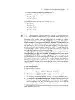
the label ‘hw’ and colored marks refer to measured results. Figure 6-31 com-
pares SW and HW EC-BAID’s BER performance for
64 L and
512
c
R kchip/s in the absence of MAI (apart from the pilot which is al-
ways assumed active).
Figures 6-32 and 6-33 present the BER curves for
32 L and
512
c
R kchip/s, but in the case of medium and heavy load conditions, re-
spectively. Simulated BERs of the conventional CR are also reported for the
sake of comparison. Finally, Figures 6-34 and 6-35 compare the simulated
and measured BER performance for
128 L
and mild loading, with
1024
c
R kchip/s and 2048
c
R kchip/s, respectively. These results clearly
show that the implementation loss of the whole receiver is about 1.0 to 1.5
dB at the target BER of
3
10
for the selected configurations. This figure in-
cludes all losses experienced by the system: signal generation, distortion
owed to analog IF processing, signal quantization, synchronization loops,
etc In particular, the TX and RX clocks were not locked as is often done in
back to back laboratory breadboard evaluations, so the impairment owed to
TX/RX clock misalignment is also taken into account.
252 Chapter
6
10
-5
10
-4
10
-3
10
-2
10
-1
10
0
BER
1086420
E
b
/N
0
(dB)
WH + E-Gold
L = 64, R
c
= 512 Kchip/s
N = 1+1
J
Baid
= 1.22 10
-4
J
leak
= 0.125
EC-BAID sw
EC-BAID hw
Figure 6-31. Experimental BER performance –— see chart inset for parameters values.
0.0001
0.001
0.01
0.1
1
BER
9630
E
b
/N
0
(dB)
WH + E-Gold
L = 32, R
c
= 512 Kchip/s
N = 1+1+14
C/I = 0 dB
Asynchr. MAI
J
Baid
= 1.22 10
-4
J
leak
= 0.125
EC-BAID sw
CR sw
EC-BAID hw
Figure 6-32. Experimental BER performance –— see chart inset for parameters values.
6. Testing and Verification of the MUSIC CDMA Receiver 253
0.001
2
3
4
5
6
7
0.01
2
3
4
5
6
7
0.1
2
3
4
5
6
7
1
BER
1086420
E
b
/N
0
(dB)
EC-BAID sw
EC-BAID hw
CR sw
WH + E-Gold
L = 32, R
c
= 512 Kchip/s
N = 1+1+22
C/I = 0 dB
Asynchr. MAI
J
Baid
= 3.05 10
-5
J
leak
= 0.125
Figure 6-33. Experimental BER performance –— see chart inset for parameters values.
0.001
2
3
4
5
6
7
0.01
2
3
4
5
6
7
0.1
2
3
4
5
6
7
1
BER
9630
E
b
/N
0
(dB)
EC-BAID sw
CR sw
EC-BAID hw
CR hw
WH + E-Gold
L = 128, R
c
= 1024 Kchip/s
N = 1+1+30
C/I = 0 dB
Asynchr. MAI
J
Baid
= 1.22 10
-4
J
leak
= 0.125
Figure 6-34. Experimental BER performance –— see chart inset for parameters values.
254 Chapter
6
0.001
2
3
4
5
6
7
0.01
2
3
4
5
6
7
0.1
2
3
4
5
6
7
1
BER
129630
E
b
/N
0
(dB)
WH + E-Gold
L = 128, R
c
= 2048 Kchip/s
N = 1+1+30
C/I = 0 dB
Asynchr. MAI
J
Baid
= 1.22 10
-4
J
leak
= 0.125
EC-BAID sw
CR sw
EC-BAID hw
CR hw
Figure 6-35. Experimental BER performance –— see chart inset for parameters values.
Chapter 7
CONCLUSION?
No, the question mark in the title of this Chapter is not a typo. In the few
pages to follow we will try to convince the reader that the issue of good, effi-
cient design of a wireless terminal with non-conventional signal processing
functions is far from being concluded. To accomplish this, we will first sum-
marize what, in our opinion, are the main outcomes of the MUSIC project.
And then we will outline a few questions that are worth being pursued in the
future. We do hope that, in some lab, under the cover of IPs and industrial
secret, some researcher has already started pursuing them…
1. SUMMARY OF PROJECT ACHIEVEMENTS
At the moment, no one doubts about CDMA being a key technology for
the successful implementation and deployment of present-time 3G and
(much likely) future 4G wireless communication networks. The MUSIC pro-
ject, supported by the ESA Technology Research Programme (TRP), has
successfully demonstrated that advanced digital signal processing techniques
are effective in mitigating CDMA interference, thus contributing to increase
the capacity and/or quality of service of a wireless communication network
(be it satellite or terrestrial).
As the reader should have clear by now, the low-complexity interference-
mitigating solution investigated and developed in the project is particularly
suited for being implemented in mobile terminals. In addition to demonstrat-
ing a good agreement of measurements with theoretical and simulation re-
sults, the project has also demonstrated the possibility to integrate advanced
CDMA interference-mitigation techniques into a single ASIC device. In par-
ticular, the design flow adopted when implementing ancillary functions on
FPGAs allows an easy re-use of the resulting architecture to come to an
overall integration of the receiver into a single ASIC with modest complex-
ity and power consumption. Of course, interference mitigation is not the sole
256 Chapter
7
advanced DSP feature that has to be incorporated into an advanced wireless
terminal. Channel coding, audio/video/image compression, challenge the
designer as well. The issues to be faced for efficient System-on-a-Chip
(SoC) design are still the fundamental ones: complexity and power. These
two factors have to be carefully traded-off for pure performance to come to a
final efficient design. The project continually faced such an issue, and we
hope that the book succeeded in clearly showing this to the reader.
A further fundamental achievement lies in the area of methodology rather
than in the domain of “pure” state-of-the-art results. The project team is con-
vinced of having attained the right attitude for close cooperation between
system-level and HW-level designers, which in a word leads to efficient co-
design. At the end of the project all communication engineers started “think-
ing HW”, in the sense that they could re-formulate their algorithms from the
very start in order to make them easier to implement by the VLSI/chip archi-
tects. And the latter could at the end of the project suggest many non-trivial
modifications to the system-level DSP algorithms to make them more effi-
cient form the “pure performance” standpoint (i.e., they learnt “thinking
DSP”). This is actually the Holy Graal of every communication terminals
design team.
2. PERSPECTIVES
Although the role of satellites in 3G system is currently still being de-
bated, it seems reasonable to assume that the satellite network can integrate
with IMT terrestrial networks to carry out two fundamental functions: i) en-
hancing the modest broadcasting capabilities of the terrestrial network, and
ii) acting as a gap-filler in poorly covered areas. Thus, the design and low-
cost implementation of dual-mode terminals operating on similar carrier fre-
quencies appears a mandatory issue. Just like mandatory appear further stud-
ies and experimentation on the performance of interference-mitigation in a
mixed satellite/terrestrial environment for the reasons above. This is the ap-
proach pursued by ESA, which is about to complete the development of a
comprehensive 3G W-CDMA satellite UMTS (S-UMTS) test-bed that will
allow to fully characterize the EC-BAID performance in the forward link of
a multi-beam multi-satellite (mobile) environment [Cai99]. To this respect,
more is still to be done from the theoretical as well as the experimental point
of view to assess the performance of adaptive interference-mitigation on a
terrestrial mobile radio channel which is mainly plagued by frequency selec-
tive fading effects.
One other issue that was not touched upon in this project is the interplay
between IMD and powerful channel coding techniques such as Turbo
7. Conclusion? 257
[Ber96] and Low-Density Parity Check (LDPC) codes [Mac99]. As is
known, the two are both based on powerful iterative decoding techniques
that allow to attain unprecedented BER performances, remarkably close to
the celebrated Shannon’s bound. We see that a few misconceptions are
building up around this issue, notably that IMD is useless when Turbo or
LDPC coding is used. We do not believe so, and we hope to see soon a book
on this topic …
A third issue that in our opinion is to be tackled soon is the applicability
of CDMA with IMD techniques to decentralized, infrastructureless, ad-hoc
networks [Jab02].A decentralized wireless network has no “reference” nodes
(as the base stations in a cellular system) since any node can at the same time
act as terminal or intermediate with routing functions: this enables the wire-
less network to establish multi-hop communication links, just as is common-
place in fixed networks. Such architecture lets one to envisage a communica-
tion scenario characterized by low-to-medium capacity and very low cost,
with easy and flexible access. Some applications of such a scenario come
immediately to our mind as for instance a “private citizen network” that de-
velops with no infrastructures to connect a group of users within a metro-
politan area (e.g., students within a University campus, workers in a big
plant or in an airport etc.). A more ambitious scenario might also be a ubiq-
uitous vehicular network whose nodes are standard radio-communication
terminals aboard cars. This would give each car a certain communication
capacity to handle not only automotive-related information (such as traffic
control, weather, emergency etc.), but low-rate multimedia communications
as well (audio, image, Internet browsing etc.). Is CDMA suited to this pic-
ture? Is IMD a good feature to increase capacity in such scenario? Will ad-
hoc networking be the winning paradigm for 4G systems? Will wireless ad-
hoc terminals with advanced DSP and routing functions be implementable as
a SoC? Trying to answer questions like these, and succeeding in doing so, is
what we call, “the pleasure of doing good research”. For a better living, eve-
ryone should experience such a thrill. Even once in a lifetime might be
enough …
This page intentionally left blank
References
[Ada97] F. Adachi, M. Sawahashi, K. Okawa, “Tree-Structured Generation of Orthogo-
nal Spreading Codes with Different Lengths for Forward Link of DS CDMA
Mobile Radio”, IEE Electronics Letters, Vol. 33, No. 1, 2nd January 1997,
pp. 27-28.
[Ada98] F. Adachi, M. Sawahashi, H. Suda, “Wideband DS-CDMA for Next-Generation
Mobile Communications Systems”, IEEE Communications Magazine, Septem-
ber 1998, pp. 56-69.
[Ahm75] N. Ahmed, K.R. Rao, Orthogonal Transforms for Digital Signal Processing,
New York: Springer-Verlag, 1975.
[Alb89] T. Alberty, V. Hespelt, “A New Pattern Jitter-Free Frequency Error Detector”,
IEEE Transactions on Communications, Vol. 37, No. 2, February 1989.
[aptix]
[arc]
[arm]
[Ber96] C. Berrou, A. Glavieux, “Near Optimum Error Correcting Coding and Decod-
ing: Turbo Codes”, IEEE Transactions on Communications, Vol. 44, No. 10,
pp 1261-1271, October 1996.
[Bha02] H. Bhatnagar, Advanced ASIC Chip Synthesis, Kluwer Academic Publishers,
2002.
[Bou02] D. Boudreau, G. Caire, Corazza G.E., R. De Gaudenzi, G. Gallinaro, M. Luglio,
R. Lyons, J. Romero-Garcia, A. Vernucci, H. Widmer, “Wideband-CDMA for
the UMTS/IMT-2000 Satellite Component”, IEEE Transactions on Vehicular
Technology, Vol. 51, No. 2, March 2002,. pp. 306-331.
[caden]
[Cai99] G. Caire, R. De Gaudenzi, G. Gallinaro, R. Lyons, M. Luglio, M. Ruggieri, A.
Vernucci, H. Widmer, “ESA Satellite Wideband CDMA Radio Transmission
Technology for the IMT-2000/UMTS Satellite Component: Features & Per-
formance”, Proc. IEEE GLOBECOM '99, Rio De Janeiro, Brazil, 5-9 Decem-
ber 1999.
[celox]
260 An Experimental Approach to CDMA and Interference Mitigation
[Chi92] S. Chia, “The Universal Mobile Telecommunication System”, IEEE Communi-
cations Magazine, December 1992, pp. 54-62.
[Cla00] T. Claasen, “First time right silicon but to the right specification”, IEEE DAC
2000, Los Angeles, Keynote, CA, USA, 5-9 June 2000.
[Cla93] F. Classen, H. Meyr, P. Sehier, “Maximum Likelihood Open Loop Carrier Syn-
chronization for Digital Radio”, In the Proceedings of the IEEE ICC 93, Ge-
neva, Switzerland, May 1993.
[cowar]
[Dah98] E. Dahlman, B. Gudmundson, M. Nilsson, J. Skökld, “UMTS/IMT-2000 Based
on Wideband CDMA”, IEEE Communications Magazine, September 1998, pp.
70-80.
[DAn94] N.A. D’Andrea, U. Mengali ,”Noise Performance of Two Frequency-Error De-
tectors Derived from Maximum Likelihood Estimation Methods”, IEEE Trans-
actions on Communications, Vol. 41, No. 2, February 1994.
[De03a] R. De Gaudenzi, L. Fanucci, F. Giannetti, E. Letta, M. Luise, M. Rovini, “De-
sign, Implementation and Verification through a Real-Time Test-Bed of a
Multi-Rate CDMA Adaptive Interference Mitigation Receiver for Satellite
Communication”, IJSCN, International Journal on Satellite Communications
and Networking, Vol. 21, Special Issue “Interference Suppression Techniques
for Satellite Systems”, March 2003, Pages 39-64.
[De03b] R. De Gaudenzi, L. Fanucci, F. Giannetti, M. Luise, M. Rovini “Satellite Mo-
bile Communications Spread-Spectrum Receiver”, IEEE Aerospace and Elec-
tronic Systems Magazine, Vol. 18, Issue 8, August 2003, pp. 23-30.
[De98a] R. De Gaudenzi, F. Giannetti, M. Luise, “Design of a Low-Complexity Adap-
tive Interference-Mitigating Detector for DS/SS Receivers in CDMA Radio
Networks”, IEEE Transactions on Communications, Vol. 46, No. 1, January
1998, pp. 125-134.
[De98b] R. De Gaudenzi, F. Giannetti, M. Luise, “Signal Synchronization for Direct-
Sequence Code-Division Multiple Access Radio Modems”, European Transac-
tions on Telecommunications, Vol. 9, No. 1, January/February 1998, pp. 73-89.
[De98c] R. De Gaudenzi, F. Giannetti, “DS-CDMA Satellite Diversity Reception for
Personal Satellite Communication: Satellite-to-Mobile Link Performance
Analysis”, IEEE Transactions on Vehicular Technology, Vol. 47, No. 2, May
1998, pp. 658-672.
[De98d] R. De Gaudenzi, F. Giannetti, M. Luise, “Signal Recognition and Signature
Code Acquisition in CDMA Mobile Packet Communications”, IEEE Transac-
tions on Vehicular Technology, Vol. 47, No. 1, February 1998, pp. 196-208.
[De98e] R. De Gaudenzi, L. Fanucci, F. Giannetti, M. Luise, “VLSI Implementation of a
Signal Recognition and Code Acquisition Algorithm for CDMA Packet Receiv-
ers”, IEEE Journal on Selected Areas in Communications, Vol. 16, No. 9, De-
cember 1998, pp. 1796-1808.
[DeG91] R. De Gaudenzi, C. Elia, R. Viola, “Band-Limited Quasi-Synchronous CDMA:
A Novel Satellite Access Technique for Mobile and Personal Communication
Systems”, IEEE Journal on Selected Areas in Communications, Vol. 10, Febru-
ary 1991, pp. 328-343.
[DeG93] R. De Gaudenzi, M. Luise, R. Viola, “A Digital Chip Timing Recovery Loop
for Band-Limited Direct-Sequence Spread-Spectrum Signals”, IEEE Transac-
tions on Communications, Vol. 41, No. 11, November 1993.
References 261
[DeG96] R. De Gaudenzi, F. Giannetti, M. Luise, “Advances in Satellite CDMA Trans-
mission for Mobile and Personal Communications”, Proceedings of the IEEE,
Vol. 84, No. 1, January 1996, pp. 18-39.
[DeM94] G. De Micheli, Synthesis and Optimization of Digital Circuits, Mc Graw-Hill,
1994
[Din98] E.H. Dinan, B. Jabbari, “Spreading Codes for Direct Sequence CDMA and
Wideband CDMA Cellular Networks”, IEEE Communications Magazine,
September 1998, pp. 48-54.
[Dix94] R.C. Dixon, Spread Spectrum Systems with Commercial Applications, New
York: Wiley Interscience, 1994.
[Due95] A. Duel-Hallen, J. Holtzman, Z. Zvonar, “Multiuser Detection for CDMA Sys-
tems”, IEEE Personal Communications, April 1995, pp. 46-58.
[Fan01] L. Fanucci, E. Letta, M. Rovini, G. Colleoni, R. De Gaudenzi, F. Giannetti, M.
Luise, “A Multi-Rate Real-Time Test-Bed for Low-Complexity Adaptive Inter-
ference Mitigation in CDMA Transmission”, International Workshop on Digital
Signal Processing Techniques for Space Communications, DSP 2001, 1-3 Octo-
ber 2001, Lisboa, Portugal.
[Fan02] L. Fanucci, M. Rovini, “A Low-Complexity and High-Resolution Algorithm to
Estimate the Magnitude of Complex Number”, IEICE Transactions on Funda-
mentals, Vol. E85-A, No. 7, July 2002, pp. 1766-1769.
[Fer99] A. Ferrari, A. Sangiovanni-Vincentelli, “System Design: Traditional Concepts
and New Paradigms”, Proceeding of the IEEE ICCD 1999, pp. 2-12, Austin,
Texas, USA, 10-13 October 1999.
[Fon96] M H. Fong, V.K. Bhargava, Q. Wang, “Concatenated Orthogonal/PN Spread-
ing Sequences and Their Application to Cellular DS-CDMA Systems with Inte-
grated Traffic”, IEEE Journal on Selected Areas in Communications, Vol. 14,
No. 3, April 1996, pp. 547-558.
[Gar88] F.M. Gardner, “Demodulator Reference Recovery Techniques Suited for Digital
Implementation”, Final Report, ESTEC Contract No. 6847/86/NML/DG,
ESA/ESTEC, The Netherlands, August 1988.
[Gia97] F. Giannetti, “Capacity Evaluation of a Cellular CDMA System Operating in
the 63-64 GHz Band”, IEEE Transactions on Vehicular Technology, Vol. 46,
No. 1, February 1997, pp. 55-64.
[Gil91] K.S. Gilhousen, I.M. Jacobs, R. Padovani, A.J. Viterbi, L.A. Weaver, C.E.
Wheatley, “On the Capacity of a Cellular CDMA System”, IEEE Transactions
on Vehicular Technology, Vol. 40, No. 5, May 1991, pp. 303-312.
[Gilch] C.E. Gilchriest, “Signal-to-Noise Monitoring”, JPL Space Programs Summary
37-27, Vol. IV, pp. 169-184.
[Gol67] R. Gold, “Optimal Binary Sequences for Spread Spectrum Multiplexing”, IEEE
Transactions on Information Theory, Vol. 13, October 1967, pp. 619-621.
[Gol68] R. Gold, “Maximal Recursive Sequences with 3-valued Recursive Cross-
Correlation Functions”, IEEE Transactions on Information Theory, January
1968, pp. 154-156.
[Gra02] M. Gray, “Platforms: a way to get aboard the express train”, Proc. of SAME
2002, Sophia Antipolis, France, 9-10 October 2002.
[Har97] “HSP50110 Digital Quadrature Tuner”, data sheet, Harris Semiconductors,
January 1997.
[Hau01] J. Hausner, “Integrated Circuits for Next Generation Wireless System”, Pro-
ceedings of the ESSCIRC 2001, Villach, Austria, 18-20 September 2001.
262 An Experimental Approach to CDMA and Interference Mitigation
[hcmos] HCMOS8D 0.18µm Standard Cells Family, CB65000 Series, STMicroelectron-
ics, data sheet, March 2002.
[hitac]
[Hog81] E.B. Hogenauer, “An Economical Class of Digital Filters for Decimation and
Interpolation”, IEEE Transactions on Acoustics, Speech, and Signal Processing,
April 1991, pp. 155-162.
[Hon95] M. Honig, U. Madhow, S. Verdù, “Blind Adaptive Multiuser Detection”, IEEE
Transactions on Information Theory, Vol. 41, No. 4, July 1995, pp. 944-960.
[Hon98] M.L. Honig, “Review of Multiuser Detection and Interference Suppression
Techniques for Satellite DS-CDMA”, ESA-ESTEC Report, ESA/ESTEC, The
Netherlands, May 1998.
[ibm]
[Jab02] B. Jabbari, “Ad-hoc/Multi-hop Networking for Wireless Internet”, European
Wireless 2002, Florence, Italy, Feb. 2002.
[Kas68] T. Kasami, “Weight Distribution of Bose-Chaudhuri-Hocquenghem Codes”, in
Combinatorial Mathematics and Its Applications, University of North Carolina
Press, Chapel Hill, NC, 1968. Also reprinted in: E.R. Berlekamp ed., Key Pa-
pers in the Development of Coding Theory, IEEE Press, New York 1974.
[Kni98] D. N. Knisely, S. Kumar, S. Laha, S. Nanda , “Evolution of Wireless Data Ser-
vices: IS-95 to cdma2000”, IEEE Communications Magazine, October 1998,
pp. 140-149.
[Koh95] R. Kohno, R. Meidan, L.B. Milstein, “Spread Spectrum Access Methods for
Wireless Communications”, IEEE Communications Magazine, January 1995,
pp. 58-67.
[Kuc91] A. Kucar, “Mobile Radio: an Overview”, IEEE Communications Magazine,
November 1991, pp. 72-85.
[Las97] J.D. Laster, J.H. Reed, “Interference Rejection in Digital Wireless Communica-
tions”, IEEE Signal Processing Magazine, May 1997, pp. 37-62.
[Lee93] W.C.Y. Lee, Mobile Communications Design Fundamentals, New York: Wiley,
1993.
[lucen]
[Mac99] D.J.C. MacKay, “Good Error Correcting Codes Based on Very Sparse Matri-
ces”, IEEE Trans on Inf. Theory, Vol. 45, No. 2, pp 399-431, 1999.
[Mad94] U. Madhow, M.L. Honig, “MMSE Interference Suppression dor Direct-
Sequence Spread-Spectrum CDMA”, IEEE Transactions on Communications,
Vol. 42, No. 12, December 1994, pp. 3178-3188.
[Mat02] P. Mate, “Redefining mobile communications”, Electronics Design Chain, Vol.
1, winter 2002, pp. 28-32.
[mathw]
[McC73] J.H. McClellan, T.W. Parks, L.R. Rabiner, “A Computer Program for Designing
Optimum FIR Linear Phase Digital Filters”, IEEE Transactions on Audio and
Electroacoustics, December 1973, pp. 506-526.
[Men97] U. Mengali, N.A. D’Andrea, Synchronization Techniques for Digital Receivers,
Plenum Press, 1997.
[mento]
[mips]
[Moe91] T. Jesupret, M. Moeneclaey, G. Ascheid, “Digital Demodulator Synchroniza-
tion - Performance Analysis”, ESA/ESTEC Contract No. 8437/89/NL/RE, June
1991.
References 263
[Moe94] M. Moeneclaey, “Overview of Digital Algorithms for Carrier Frequency Syn-
chronization”, In the Proceedings of the 4th International Workshop on DSP
Techniques Applied to Space Communications, London, United Kingdom, Sep-
tember 1994.
[Mos96] S. Moshavi, “Multi-User detection for DS-CDMA Communications”, IEEE
Communications Magazine, October 1996, pp. 124-136.
[motor]
[MUS01] “MUSIC Receiver (Multi-User & Interference Cancellation)”, ESA/ESTEC
Contract 13095/98/NL/SB, Final Report, Noordwijk, The Netherlands, Dec.
2001.
[nalla]
[Nat89] F. Natali, “AFC Tracking Algorithms”, IEEE Transactions on Communications,
Vol. 37, No. 8, August 1989.
[Nee99] R. van Nee, G. Awater, M. Morikura, H. Takanashi, M. Webster, K.W.Halford,
“New High-Rate Wireless LAN Standards”, IEEE Communications Magazine,
December 1999, pp.82-88.
[New94] P. Newson, M. Heath, “The Capacity of a Spread Spectrum CDMA System for
Cellular Mobile Radio with Consideration of System Imperfections”, IEEE
Journal on Selected Areas in Communications, Vol. 12, No. 4, May 1994, pp.
673-684.
[Oja98] T. Ojanperä, R. Prasad, “An Overview of Air Interface Multiple Access for
IMT-2000/UMTS”; IEEE Communications Magazine, September 1998, pp. 82-
95.
[Opp75] A.V. Oppenheim, R.W. Shafer, Digital Signal Processing. Englewood Cliffs,
NJ, Prentice Hall, 1975
[Pad95] J.E. Padgett, C.G. Günther, T. Hattori, “Overview of Wireless Personal Com-
munciations”, IEEE Personal Communications Magazine, January 1995, pp. 28-
41.
[Pav02] M. Pavesi, “FlexBench Tool Suite Relies on Xilinx Silicon and Software”, Xcell
Journal, Issue 42, Spring 2002, pp. 64-67.
[Pet72] W.W. Peterson, E.J. Weldon Jr., Error-Correcting Codes, 2nd ed., Cambridge,
MA: MIT Press, 1972.
[Pic82] R.L. Pickholtz, D.L. Schilling, L.B. Milstein, “Theory of Spread-Spectrum
Communications-A Tutorial”, IEEE Transactions on Communications, Vol. 30,
Mat 1982, pp. 855-884.
[Pra98] R. Prasad, T. Ojanperä, “An Overview of CDMA Evolution Toward Wideband
CDMA”, IEEE Communications Surveys, Vol. 1, No. 1, 4th Quarter 1998, pp.
2-29.
[Pro95] J.G. Proakis, Digital Communications - 3rd edition, McGraw-Hill, New York,
1995.
[Rab00] J.M. Rabaey, “Low-power silicon architectures for wireless communications”,
Proceedings of the IEEE ASP-DAC 2000, pp. 377-380, Yokohama, Japan, 25-
28 January 2000.
[Rap91] T.S. Rappaport, “The Wireless Revolution”, IEEE Communications Magazine,
November 1991, pp. 52-71.
[Rom00] J. Romero-García, R. De Gaudenzi, F. Giannetti, M. Luise, “A Frequency Error
resistant Blind CDMA Detector”, IEEE Transactions on Communications, Vol.
48, No. 7, July 2000, pp. 1070-1076.
264 An Experimental Approach to CDMA and Interference Mitigation
[Rom97] J. Romero-Garcia, R. De Gaudenzi, F. Giannetti, M. Luise, “A Frequency Error
Resistant Blind CDMA Detector”, IEEE Transactions on Communications, Vol.
48, No. 7, July 2000, pp. 1070-1076
[Sam88] H. Samueli, “The Design of Multiplierless FIR Filters for Compensating D/A
Converter Frequency Response Distortion”, IEEE Transactions on Circuits and
Systems, August 1988, pp. 1064-1066.
[Sar80] D.P. Sarwate, M.B. Pursley, “Crosscorrelation Properties of Pseudorandom and
Related Sequences”, Proceedings of the IEEE, Vol. 68, No. 5, May 1980, pp.
593-619.
[Sas98] A. Sasaki, M. Yabusaki, S. Inada, “The Current Situation of IMT-2000 Stan-
dardization Activities in Japan”, IEEE Communications Magazine, September
1998, pp. 145-153.
[Sch82] R.A. Scholtz, “The Origins of Spread-Spectrum Communications”, IEEE
Transactions on Communications, Vol. 30, May 1982, pp. 822-854.
[Sei91] S.Y. Seidel, T.S. Rappaport, S. Jain, M.L. Lord, R. Singh, “Path Loss, Scatter-
ing, and Multipath Delay Statistics in Four European Cities for Digital Cellular
and Microcellular Radiotelephone”, IEEE Transactions on Vehicular Technol-
ogy, Vol. 40, No. 4, November 1991, pp. 721-730.
[Sim85] M.K. Simon, J.K. Omura, R.A. Scholtz, B.K. Levitt, Spread Spectrum Commu-
nications, Rockville, MD: Computer Science Press, 1985.
[Smi97] M. Smith, Application Specific Integrated Circuits, Addison-Wesley, 1997
[stm]
[Syn98] R. De Gaudenzi, F. Giannetti, M. Luise, “Signal Synchronization for Direct-
Sequence Code-Division Multiple Access Radio Modems”, European Transac-
tions on Telecommunications, Vol. 9, No. 1, January/February 1998, pp. 73-89.
[synop]
[syste]
[tensi]
[ti]
[Vem96] S. Vembu, A.J. Viterbi, “Two Different Philosophies in CDMA – A Compari-
son”, In the Proceedings of the IEEE 46th Vehicular Technology Conference
VTC’96, Atlanta, April 28-May 1, 1996, pp. 869-873
[Ver86] S. Verdù, “Minimum Probability of Error for Asynchronous Gaussian Multiple
Access Channels”; IEEE Transactions on Information Theory, Vol. 32, No. 1,
January 1986, pp. 85-96.
[Ver97] S. Verdù, “Demodulation in the Presence of Multiuser Interference: Progress
and Misconceptions”, in Intelligent Methods in Signal Processing and Commu-
nications, D. Docampo, A. Figueiras-Vidal, F. Perez-Gonzales, Eds. pp. 15-44,
Birkhauser, Boston, 1997.
[Vit95] A. Viterbi, S. Vembu, “Theoretical and Practical Limits of Wireless Multiple
Access Systems”, in the Proceedings of the URSI Commsphere, Eilat, Israel,
April 1995, pp. 33-43.
[vsi]
Index
Numerics
1G system See also first generation sys-
tem
2G system See also second generation
system
3G system See also third generation sys-
tem
4G system See also fourth generation
system
A
AAF See also anti-alias filter
AC user location See also average case
user location
A-CDMA See also asynchronous code
division multiple access
AceS 9
acquisition
average time 108
parallel 105
serial 105
total time 107
ad hoc wireless network 1, 257
AD-AFC See also angle doubling auto-
matic frequency control
adaptive detector 71
adaptive interference mitigation
architecture 197
ADC See also analog to digital conver-
sion
additive white gaussian noise 34
additive white gaussian noise
generation 223
advanced mobile phone system 2
advanced mobile satellite task force 10
AFCU See also automatic carrier fre-
quency control unit
AGC See also automatic gain control
algorithm
Parks-McClellan 101
Viterbi 66
alias profile 98
AMPS See also advanced mobile phone
system
analog signal conditioning unit 82
analog to digital conversion 40
analog to digital converter 15
angle doubling automatic frequency con-
trol 119
antenna reflector 11
anti-alias filter 83
anti-image filtering 224
application specific integrated circuit 15,
255, 161
arbitrary waveform generator 224
ASCU See also analog signal condition-
ing unit
ASIC See also application specific inte-
grated circuit
ASIC
back-end design flow 216
front-end design flow 211
266 An Experimental Approach to CDMA and Interference Mitigation
synthesis constraints 215
ASMS-TF See also advanced mobile
satellite task force
asynchronous code division multiple
access 52
autocorrelation
data 25
off-zero 48
partial 44
automatic carrier frequency control unit
82
automatic gain control 140
average case user location 60
AWG See also arbitrary waveform gen-
erator
AWGN See also additive white gaussian
noise
B
balanced sequence 32
band
Ka 11
paired 8
S 11
unpaired 9
base station 55
baseband equivalent 21
beam 11
behavioral synthesis
allocation 166
description 166
mapping 166
scheduling 166
bent pipe transponder 11
BER See also bit error rate
bias 122
binary phase shift keying 38
BIST See also built in self test
built in self test 210, 213
bit error rate 38
bit error rate estimation 167
bit true 148
bit true model 167
blind detector 72
Bluetooth 4
BPSK See also binary phase shift keying
broadcast service 10
BS See also base station
BT See also bit true
C
cacheing 12
CAD See also computer aided design
CAGR See also compound annual growth
rate
carrier phase recovery unit 82, 123
carrier phase recovery unit
architecture 206
cascaded integrator and comb 94
CCTU See also chip clock tracking unit
CDM See also code division multiplexing
CDMA See also code division multiple
access
CDMA signal generation 226
CDMA signal generation
framing 226
repetition 226
CDMA signal
eye-diagram 228
cdma2000 3
cdmaOne 3, 28
CED See also chip timing error detector
cell 5
cellular communications 5
channelization code 7, 49
chip 28
chip clock tracking unit 82
chip timing error detector 109
chip
interval 28
matched filter 35
CIC See also cascaded integrator and
comb
cluster 6, 54
CMF See also chip, matched filter
CMOS See also complementary metal
oxide-semiconductor
code division multiple access 2, 41
code division multiple access
asynchronous 52
multi-carrier 5
multiuser 41
orthogonal 48
quasi-orthogonal 49
synchronous 42
wideband 8, 256
code division multiplexing 7, 41
code timing acquisition unit 82
code
channelization 7, 49
Index 267
composite 48
local replica 36
long 31
orthogonal 48
overlay 49
quasi-orthogonal 49
re-use 54
scrambling 7, 49
short 31
spreading 6
synchronous 7
traffic 49
co-design 256
compensation filter 99
complementary metal oxide-
semiconductor 14
complex envelope 21
complex spreading 34
component
in phase See also in phase component
quadrature See also quadrature com-
ponent
composite code 48
compound annual growth rate 19
computational power 163
computer aided design 161
connection
wired 1
wireless 1
constellation 22
coordinate rotation digital computer 86
CORDIC See also coordinate rotation
digital computer
CORE-A 4
correlation receiver
architecture 197
correlation
matrix 68
receiver 38
sliding 105
zero lag 33
CP-AFC See also cross-product auto-
matic frequency control
CPRU See also carrier phase recovery
unit
CR See also correlation, receiver
cross-correlation
coefficient 68
off-zero 48
partial 44
periodic 32
cross-product automatic frequency con-
trol 119
CS See also complex spreading
CTAU See also code timing acquisition
unit
curve
M 109
S 126
cycle true model 165
cyclostationarity 67
cyclostationary signal 39
D
DA See also data aided
data aided 71
data
autocorrelation 25
spectrum 25
DCO See also digitally controlled oscilla-
tor
DCS-1800 2
DD See also decision directed
DDS See also direct digital synthsizer
DDU See also digital downconversion
unit
decimation 92
decision directed 71
decorrelating
detector 68
matrix 68
I/Q 23
design rule check 220
despreading 36
detector
adaptive 71
blind 71
chip timing error 109
decorrelating 68
extended complex-valued blind an-
chored interference mitigating 72
extended complex-valued blind an-
chored interference mitigating type I
136
extended complex-valued blind an-
chored interference mitigating type II
137
frequency difference 120
frequency error 90, 108
interference mitigating 70
268 An Experimental Approach to CDMA and Interference Mitigation
minimum mean output energy 71
minimum mean square error 69
phase error 125
rotational frequency 119
timing error 83
DFD See also dual filter discriminator
digital design flow 168
digital design
partitioning 170
technology migration 168, 170
digital downconversion unit 82
digital macro cells 170
digital signal processor 15, 160
digital subscriber line 5
digital video broadcasting
terrestrial 5
digitally controlled oscillator 85
direct digital synthsizer 85
direct mobile multicasting 10
direct sequence spread spectrum 28
direct sequence spread spectrum
receiver 34
transmitter 29
Doppler shift 118
DRAM See also dynamic random access
memory
DRC See also design rule check
d-RS See also dual real spreading
DS/SS See also direct sequence spread
spectrum
DSL See also digital subscriber line
DSP See also digital signal processor
DSP compiler 164
dual filter discriminator 119
dual real spreading 33
dual-mode terminal 256
DVB-T See also digital video broadcast-
ing, terrestrial
dynamic random access memory 14
E
EAB See also embedded array block
early/late sample 108
EC-BAID ASIC pin-out
description 186
EC-BAID detector See also extended
complex-valued blind anchored inter-
ference mitigating detector
EC-BAID
adaptive correction term 199
amplitude control 198
bit true architecture 195
configuration parameters 191
handshake protocol 190
output management 207
output timing 204
reset 189, 208
symbol realignment 187, 209
EC-BAID-I See also extended complex-
valued blind anchored interference
mitigating detector, type I
EC-BAID-II See also extended complex-
valued blind anchored interference
mitigating detector, type II
EDA See also electronic design automa-
tion
EDGE See also enhanced data rate for
global evolution
EDIF See also electronic database inter-
change format
E-Gold sequence See also extended Gold
sequence
electronic database interchange format
182
electronic design automation 163
electro-static discharge 218
embedded array block 175, 228
enhanced data rate for global evolution 2
E-PN sequence See also extended
pseudo-noise sequence
equalizer 99
Ericsson 19
Ericsson Mobile platform 19
error correction technique 12
ESA See also european space agency
ESD See also electro-static discharge
Ethernet 4
european space agency 10, 77
extended complex-valued blind anchored
interference mitigating detector 72
extended complex-valued blind anchored
interference mitigating detector
type I 136
type II 137
extended Gold sequence 50
extended pseudo-noise sequence 49
F
factor
forgetting 127
Index 269
over sampling 83
fading 256
false detection probability 107
FCW See also frequency control word
FDD See also frequency division duplex-
ing or frequency difference detector
FDMA See also frequency division mul-
tiple access
FED See also frequency error detector
FH/SS See also frequency hopping spread
spectrum
field programmable gate array 255, 165,
166
finite word length effects 163
first generation system 2
fixed point model 163, 164
floating point 148
floating point model 163, 164
forgetting factor 127
forward link 11
fourth generation system 5
FP See also floating point
FPGA See also field programmable gate
array
FPGA
partitioning 171
FRAMES 4
frequency control word 86
frequency difference detector 120
frequency division duplexing 8
frequency division multiple access 6, 41
frequency error detector 90, 108
frequency hopping spread spectrum 28
frequency re-use 5, 54
frequency re-use
universal 7, 54
full custom 165
G
gap filler 11, 256
gate array 165
gate-level netlist 215
gate-level simulation 215
gateway station 11
Gauss integral function 38
general purpose interface bus 228
generalized packet radio service 2
GEO See also geostationary
geostationary 9
global mobile personal communication
systems 9
global positioning system 30
global system for mobile communications
2
Globalstar 9
GMPCS See also global mobile personal
communication systems
Gold platform 19
Gold sequence 49
GPIB See also general purpose interface
bus
GPRS See also generalized packet radio
service
GPS See also global positioning system
GSM See also global system for mobile
communications
H
handover 8
hardware description language 165
hardware design flow 165
hardware multiplexing
output selection 188
HCMOS8D technology 210
HDL See also hardware description lan-
guage
HomeRF 5
hysteresis 109
I
I/O pads
selection 216
ICI See also inter-chip interference
IEEE 802.11a-b 4
IEEE 802.15 4
IF See also intermediate frequency
IFD See also intermediate frequency,
digital
image spectrum 23, 86
IMD See also interference mitigating
detector
implementation loss 77, 164
IMT-2000 See also international mobile
telecommunications for the year 2000
in phase component 21
Infineon 19
Inmarsat 9
Intel 14
intellectual property 18, 161, 163
270 An Experimental Approach to CDMA and Interference Mitigation
inter-cell interference 6, 56, 61
inter-chip interference 39
interference mitigating detector 70
interference mitigation 12
interference
cancellation 66
inter-cell 6, 56, 61
intra-cell 7, 56, 61
multiple access 7, 44
intermediate frequency 21, 81
intermediate frequency
digital 86
international mobile telecommunications
for the year 2000 3
international technology roadmap for
semiconductor 18
international telecommunications union 3
intra-cell interference 7, 56, 61
intra-cell interference
factor 63
IP See also intellectual property
Iridium 9
IS-154 2
IS-95 2
IS-95 3
IS-95 28
ITRS See also international technology
roadmap for semiconductor
ITU See also international telecommuni-
cations union
K
Kasami
sequence set 50
L
LabView application 230
latency 108, 180
layout versus schematic 220
LDPC See also low density parity check
code
LE See also logic element
least significant bit 90
LEO See also low Earth orbiting
LFSR See also linear feedback shift reg-
ister
linear feedback shift register 32
linear interpolation unit 82
linear modulation 23
link
forward 11
reverse 11
service 11
user 11
LIU See also linear interpolation unit
local replica code 36
localization 9
lock
indicator 109
metrics 127
logic element 182, 231
logic synthesis 165, 182
long code 31
look up table 86
low density parity check code 257
low Earth orbiting 9, 119
LSB See also least significant bit
LUT See also look up table
LVS See also layout versus schematic
M
M curve 109
magnitude of complex numbers
approximation 199
MAI See also multiple access interfer-
ence
matrix
correlation 68
decorrelating 68
maximal length sequence 32
MC-CDMA See also code division mul-
tiple access, multi-carrier
mean time to lose lock 77
medium Earth orbiting 119
MEO See also medium Earth orbiting
microprocessor 160
minimum mean output energy detector 71
minimum mean square error detector 69
missed detection probability 107
MMOE detector See also minimum mean
output energy detector
MMSE detector See also minimum mean
square error detector
mobile Internet service 8
mobile terminal 55
modulated signal 21
modulation
binary phase shift keying 38
linear 23